Abstract
The removal of particulate contaminants adhering to a surface has been investigated using a dry ice blasting system. Monosized spherical latex particles of micron and submicron sizes were used as particulate contaminants, while the dry ice jet was produced by the thermal expansion of liquid carbon dioxide (CO2). Removal of the contaminants was observed in situ using a high-speed microscope camera and quantified through digital image analysis. The experimental results showed that dry ice blasting performs well for surface cleaning, which is attributed to the collision of the dry ice particles with the contaminants. For submicron-sized contaminants, a lower temperature jet was required in order to produce a larger number of dry ice particles to enhance the removal efficiency. The removal efficiency increased with an increase of the jet pressure on the surface. In addition, a theoretical analysis of the moments of forces caused by particle impact and aerodynamic drag showed that particle impact is primarily responsible for removal. Furthermore, the effect of the dry ice cleaning was visually observed by applying it to the removal of a film resin covering a surface.
NOMENCLATURE
| a s | = |
contact radius at separation (m); |
| C c | = |
Cunningham slip correction factor (–); |
| D | = |
reduced particle diameter [=D p1 D p2/(D p1+ D p2)] (m); |
| D p1 | = |
diameter of dry ice particle (m); |
| D p2 | = |
diameter of particulate contaminant (m); |
| E | = |
Young's modulus (Pa); |
| F a | = |
adhesion force (N); |
| F c | = |
impact force (N); |
| F d | = |
drag force (N); |
| f | = |
dimensionless coefficient of force (–); |
| g | = |
dimensionless coefficient of moment (–); |
| k 12 | = |
elastic characteristic [=(1−ν2 1)/E 1+(1−ν2 2)/E 2] (Pa−1); |
| k 23 | = |
elastic characteristic [=(1−ν2 2)/E 2+(1−ν2 3)/E 3] (Pa−1); |
| M c | = |
moment caused by impact force (N m); |
| M d | = |
moment caused by drag force (N m); |
| M t | = |
moment about center of mass of particulate contaminant (N m); |
| m | = |
reduced mass [=m 1 m 2/(m 1 + m 2)] (kg); |
| m 1 | = |
mass of dry ice particle (kg); |
| m 2 | = |
mass of particulate contaminant (kg); |
| N 0 | = |
initial number of particulate contaminants (m−2); |
| N r | = |
number of residual particulate contaminants (m−2); |
| Rep2 | = |
particle Reynolds number (–); |
| r* | = |
moment ratio of impact force to drag force (–); |
| u | = |
fluid velocity pointing to the center of a particulate contaminant (m s−1); |
| u 0 | = |
core velocity of dry ice jet (m s−1); |
| v | = |
impact velocity (m s−1); |
| W 23 | = |
surface energy per unit area (J m−2); |
| x | = |
horizontal position on the test plate surface (m). |
Greek Letters
| γ | = |
solid-to-gas mass flow ratio (–); |
| η | = |
particle removal efficiency (–); |
| θ | = |
contact angle of the particulate contaminant adhering to surface (rad); |
| λ | = |
mean free path of gaseous CO2 (m); |
| μ | = |
fluid viscosity (Pa s); |
| ν | = |
Poisson's ratio (–); |
| ρ | = |
density of fluid (kg m−3); |
| ρ 1 | = |
density of dry ice (kg m−3); |
| ρ 2 | = |
density of polystyrene (kg m−3); |
| φ | = |
impact angle (rad). |
Subscripts
| 1 | = |
particle (dry ice); |
| 2 | = |
particulate contaminant adhering to wall (polystyrene); |
| 3 | = |
wall (glass). |
INTRODUCTION
In general, dust and other impurities deposit on surfaces. If such airborne contaminants deposit on high precision products, their properties may be influenced resulting in a reduction in quality. For example, a conductive particle less than 1 μm in size that adheres to a substrate in an integrated circuit package may cause an electrical short. Even if high-efficiency air filtration systems are installed in the factory, airborne contaminants cannot be completely eliminated; therefore, effective surface cleaning methods are required. Various surface cleaning methods have already been developed and some of them are used industrially. These cleaning methods can be divided into two categories: (1) wet cleaning, and (2) dry cleaning. Wet cleaning is known to be effective for removing fine particles even if the particle size is less than 0.1 μm. Chemical additives or irradiation by ultrasonic waves can also be used to enhance the cleaning efficiency. Although wet cleaning has been widely used in industry due to its high removal efficiency, it requires a drying process after cleaning and results in the processing of a large amount of water. In addition, residues in the solution may deposit onto the surface after drying and cause recontamination.
In contrast, dry surface cleaning is simple and environment friendly since a large amount of solution is not required. In 1994, Masuda et al. (Citation1994) studied the removal of micron-sized particulate contaminants adhering to surfaces by an air jet. Gotoh et al. (1994a, 1994b, 1995) further studied the effect of the surface material, contaminant particle size, and RH on the removal efficiency. Otani et al. (Citation1995) investigated the removal of submicron-sized particles using consecutive pulsed air jets and analyzed the removal efficiency taking into account the ratio of drag force to adhesion force. To improve the removal efficiency, electrostatic precharging and vibrating air jets were also investigated (Gotoh et al. Citation1996). Smedley et al. (1999a, 2001) slowly translated a sample under a steady jet to avoid the transient effects associated with jet startup. The translating gas jet produces a long clean path that provides very good statistics for exploring the effect of jet parameters. In addition, Smedley et al. (Citation1999b) did experiments using impinging shock waves, which effectively cleaned a large surface area.
Although air jet cleaning is simple and convenient, the removal of fine particles as small as a submicron in diameter is difficult. This is because the drag force caused by airflow is ineffective for the finer particles. In addition, the air jet cannot effectively remove film contaminants. Therefore, further improvement must be made.
Abrasive blasting is one example of a dry cleaning method. Its removal efficiency is enhanced by the collision of abrasive particles mixed in with the airflow. The impact force is effective for the removal of film contaminants as well as particulate contaminants. However, abrasive blasting is not suitable for fragile surfaces because the strong impact forces may cause surface damage. In addition, the small abrasive particles can cause secondary contamination.
For dry surface cleaning, dry ice has also been employed. The concept of surface cleaning using dry ice snow, which is produced by expanding liquid carbon dioxide (CO2), was proposed. The effectiveness of surface cleaning using dry ice snow was demonstrated by Hoenig (Citation1986). It was thought that the impact force of the dry ice particles would enhance the efficiency of the removal of particulate contaminants. Since the dry ice particles sublimate to CO2 gas after impact, there is no deposition of the dry ice particles; however, impurities in the CO2 should be taken into consideration (Sherman et al. Citation1994; Sherman Citation2007). Dry ice blasting is also expected to effectively remove film contaminants composed of organic compounds (Sherman and Whitlock Citation1990; Sherman et al. Citation1991; Sherman et al. Citation1994; Sherman Citation2007). The composition of organic contaminants before and after cleaning was analyzed using X-ray photoelectron spectroscopy. Furthermore, the cleaning performance of dry ice blasting was investigated using infrared spectroscopy (Hills Citation1995), and field emission scanning microscopy (Dangwal and Müller Citation2007). Dry ice cleaning methods have excellent performance for many applications, such as the cleaning of products or equipment in electrical, automobile, and food industries, etc. However, the removal mechanism is not yet clear. There are several possible removal mechanisms for dry ice cleaning: (1) kinetic separation based on the momentum transfer from the dry ice particles to contaminants, (2) aerodynamic drag separation, (3) chemical separation caused by the dissolution of residues into liquid CO2, and (4) electrostatic separation caused by the sweep of the contaminants combined with the charged dry ice particles (Sherman et al. Citation1991; Hills Citation1995; Jackson and Carver Citation1999).
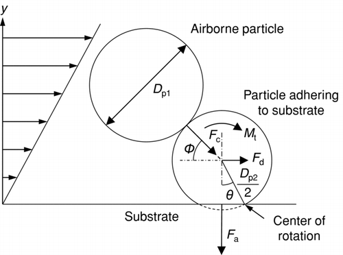
The kinetic separation and the aerodynamic drag separation have been investigated by taking into account the forces acting on a particle adhering to a surface (Kousaka et al. Citation1980; Wang Citation1990; Tsai et al. 1991; Matsusaka and Masuda Citation1996; Adhiwidjaja et al. Citation2000; Theerachaisupakij et al. Citation2003); particle removal was explained by the moments of the forces. shows the basic concept of a moment balance model for a particle adhering to a substrate. There are three main forces: impact force caused by an airborne particle (F c), drag force (F d), and adhesion force (F a). Gravitational force can be neglected since the contaminants are generally small. In , D p1 and D p2 are the diameters of the airborne particle and the particle adhering to the substrate, respectively, φ is the impact angle, θ is the contact angle based on elastic deformation, and M t is the moment of force at the center of mass of the particle, which is caused by the shear flow. The balance of the moments of forces is represented by
The moment balance model was also used for dry ice cleaning and showed that rolling removal of particulate contaminants is more significant than sliding removal based on the force balance (Toscano and Ahmadi 2003). However, if the particulate contaminants are not spherical, the sliding model may be significant (Banerjee and Campbell Citation2005). To fully elucidate the mechanism of particle removal, fundamental research is needed, and the phenomenon needs to be observed microscopically. In addition, the measurement of the temperature of the dry ice jet is important to analyze the removal efficiency since the state of the dry ice particles in a jet flow depends on the temperature (Liu et al. Citation2010).
In the present study, the removal of particulate contaminants adhering to a surface by dry ice blasting is experimentally investigated. Particle removal is observed by a high-speed microscope camera and the time course of the particle removal efficiency is obtained. An experiment using an air jet is also conducted to clarify the effect of the impact of the dry ice particles. In addition, the temperature of the dry ice jet is continuously measured to study the variation of the removal efficiency. Theoretical calculations based on the moment balance model are carried out to discuss the particle removal mechanism. Moreover, a visualization of the surface cleaning is performed.
EXPERIMENTAL APPARATUS AND PROCEDURE
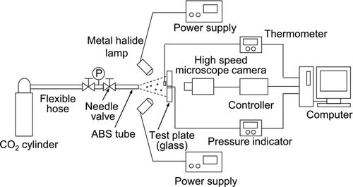
shows the experimental apparatus for surface cleaning by dry ice blasting. The dry ice jet was produced by expanding high-purity liquid CO2. To do this, a flexible hose made of stainless steel was connected to a high-pressure CO2 cylinder. At the end of the hose, a needle valve was installed to control the flow rate of the dry ice jet. A pressure gauge was set at the inlet of the needle valve to measure the inner pressure of the CO2; the pressure measured in the experiments was over 6 MPa. The flexible hose and the needle valve were thermally insulated to reduce heat transfer between the environment and the equipment. A 50 mm long acrylonitrile-butadiene-styrene (ABS) tube was installed at the end of the needle valve to serve as an agglomeration chamber (Liu et al. Citation2010). The agglomerated dry ice particles were exhausted from the tube with the CO2 gas.
A test plate (76 × 26 mm) made of 1 mm thick transparent glass was fixed in the surface cleaning experiment. The plate was previously contaminated by monosized spherical latex particles with diameters of 2.92 μm and 0.75 μm (Duke Scientific Corp.). The preparation procedure is as follows: (1) colloidal particles were aerosolized by a nebulizer; (2) particles carried by the airflow were dried by passing though an annular cylinder containing silica gel; (3) the airborne particles deposited onto the surface of the plate. The initial number of particles per unit area of the surface was about 100 mm−2 for the 2.92-μm particles and about 600 mm−2 for the 0.75-μm particles.
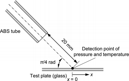
shows the configuration of the ABS tube and test plate. The inner diameter of the ABS tube used for the experiment was 6 mm. The angle of incidence was π/4 rad and the distance from the tip of the tube to the center of the test plate was 20 mm in the axial direction. To evaluate the strength of the jet flow on the surface, the local pressure at the center of the surface, i.e., at the impingement point of the jet axis, was measured by a pressure sensor (AP-43, Keyence Corp.). A pressure tap of about 1 mm in diameter was installed at the test plate, and the pressure sensor was connected from behind. The temperature of the dry ice jet was also measured at the same position using a thermometer. Particle removal was observed from behind the test plate using a high-speed microscope camera (Fastcam-Max, Photron Ltd.). The efficiency of the removal of particulate contaminants was obtained by digital image analysis.
To visualize the surface cleaning, black resin (synthetic acrylic resin) dissolved in organic liquid was sprayed vertically on a test plate. Before the experiment was carried out, the resin was dried at room conditions for 1500 s until it formed a solid film. The average thickness of the film was 45 μm. All the experiments were conducted at room conditions (temperature: 25 ± 2°C; RH: 40–60%).
EXPERIMENTAL RESULTS AND DISCUSSION
Local Pressure on Surface
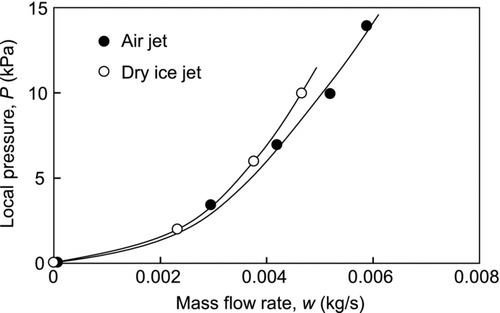
shows the local pressure at the impingement point of the jet axis as a function of the mass flow rate of the dry ice jet and air jet. To observe the variation of the particle removal efficiency in detail, low mass rates were used. The pressures were measured under steady state conditions with flow temperatures of 25°C and about −70°C for the air jet and dry ice jet, respectively. The local pressure increased with the mass flow rate, and the results for both the air and dry ice jets are similar. Since the local pressure correlates with the mass flow rate of the jet flow, the local pressure can be used to evaluate the strength of the jet flow.
Effective Cleaning Area
To investigate the particle removal efficiency, test plates contaminated with monosized latex particles were cleaned by the dry ice jet. The removal efficiency, η, is defined by
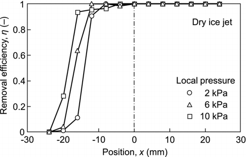
shows the efficiency of the removal of 2.92-μm particulate contaminants as a parameter of the local pressure. In this experiment, the duration of dry ice blasting was set at 10 s. The particulate contaminants were completely removed at the center of the plate and downstream; however, the removal efficiency decreased at a point 15 mm from the center toward the opposite side, and reached zero at x = −25 mm. The effective removal area increased with an increase in the local pressure. Although the experiments were conducted under different RHs in a range of 40–60%, there was no effect of the RH on removal efficiency.
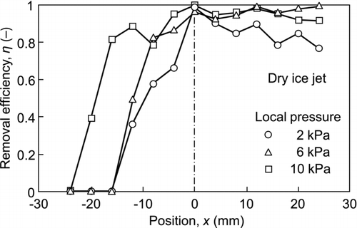
An experiment to remove 0.75-μm particulate contaminants was also carried out. The results are shown in . Although the removal efficiency was lower than that for the 2.92-μm particulate contaminants, common characteristic features were evident, i.e., the removal efficiency was high downstream but low on the opposite side. Since submicron-sized contaminants are more difficult to remove from the surface, a higher local pressure was required to increase the removal efficiency.
Time-Dependent Particle Removal Efficiency
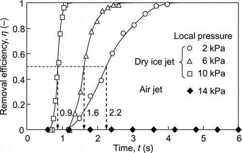
shows the time course of the efficiency of the removal of 2.92-μm particulate contaminants adhering to the center of the surface. The onset time (t = 0) is the time at which the valve is opened. When using dry ice blasting, particle removal begins after a delay of a few seconds after starting the experiment, and the removal efficiency increases as time elapses. In addition, the particle removal efficiency quickly increases with increased in the local pressure. The median values of the time to remove the contaminants at local pressures of 2, 6, and 10 kPa were 2.2, 1.6, and 0.9 s, respectively. As the local pressure increases, the aerodynamic drag force acting on the contaminants also increases; however, the drag force is not a main factor in the removal of the particles. This is evident in that the air jet is not effective for particle removal even though the local pressure is higher for the air jet than that for the dry ice jet, as shown in . The dry ice jet has a gas-solid two-phase flow; thus, the impact force between the dry ice particles and the contaminants is important for particle removal.
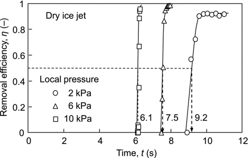
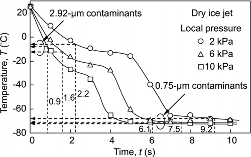
shows the experimental results for the 0.75-μm particulate contaminants. The dry ice jet can remove even submicron-sized particles; however, the time to remove them is longer than that for the 2.92-μm particulate contaminants. The median values of the time required to remove the 0.75-μm particles at the local pressures of 2, 6, and 10 kPa were 9.2, 7.5, and 6.1 s, respectively. The median time for removal is an important factor in evaluating dry ice cleaning. To elucidate the time dependence, the state of the dry ice jet flow as well as the conditions of the contaminants must be discussed. Since the state of the dry ice jet varies according to the temperature, the time-dependency of the temperature must be determined.
Temperature of the Dry Ice Jet
The CO2 exists as a gas at room conditions; however, as liquid CO2 expands to atmospheric pressure, the temperature of the jet flow decreases and dry ice particles are produced. Therefore, the state of the dry ice particles in the jet flow is strongly related to the temperature and pressure. shows the time course of the temperature of the dry ice jet over which the temperature decreases from room temperature to about −70°C. In this experiment, there were two stages of temperature reduction. A similar tendency was reported in our previous study (Liu et al. Citation2010). After the second temperature decrease, many agglomerated dry ice particles were produced in the jet flow. Since these experiments were conducted at rather low mass flow rates, the temperature decrease can be clearly observed. At a higher local pressure, the temperature quickly decreases because large amounts of liquid CO2 expand resulting in efficient cooling of the jet flow. Therefore, dry ice particles are more quickly produced at higher local pressures; the collisions of the dry ice particles with the contaminants will enhance the removal efficiency. In addition, the adhesive force between the contaminants and the surface can be affected by the temperature. If water molecules accumulate at the contact point at room temperature and a liquid bridge is formed, the contaminants experience a liquid bridge force in addition to the van der Waals force. When the temperature is sufficiently decreased by the dry ice jet, the water will freeze, and the liquid bridge force will be changed into the interaction force between solids with the ice. This phenomenon will also affect the removal efficiency.
To correlate the temperature with the particle removal efficiency, the median values of the time to remove the contaminants ( and ) are added into . The temperatures for the removal of the 2.92-μm and 0.75-μm contaminants were about −10°C and −70°C, respectively. Therefore, the time dependency of the removal can be well explained by the temperature variation of the dry ice jet.
Particle Removal Rate
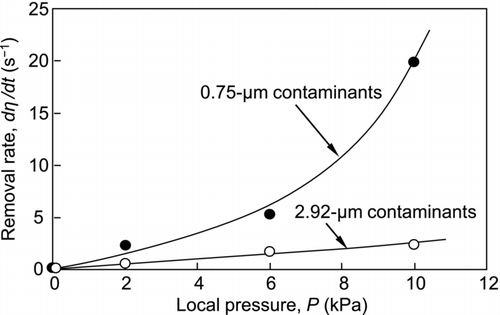
A normalized particle removal rate is obtained by differentiating the particle removal efficiency with respect to time. The rates for the removal of 2.92- and 0.75-μm particulate contaminants at half removal efficiency are shown in . The removal rate increases with increases in the local pressure. This is a natural consequence of the increase in the strength of the jet flow. In addition, this figure shows that the removal rate for 0.75-μm particles is much higher than that for 2.92-μm particles. The difference caused by the contaminant size can be explained as follows:
Submicron-sized contaminants are more difficult to remove than micron-sized contaminants; thus, removal of the submicron-sized contaminants occurs at lower temperatures at which a larger number of agglomerated dry ice particles are formed to collide with the contaminants. The impact force will be enhanced with an increase in the inertia of the agglomerated dry ice particles. In addition, they do not sublimate as quickly as smaller dry ice particles and are therefore more effective for particle removal. On the other hand, micron-sized contaminants can be removed at a higher temperature than submicron-sized contaminants. Under these conditions, the lack of agglomerated dry ice particles would result in a lower removal rate.
Effect of the Impact of Dry Ice Particles on Particulate Contaminant Removal
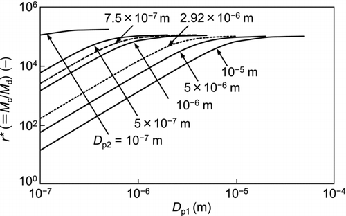
When applying gas-solid two-phase flow to surface cleaning, particulate contaminants on the surface experience both an aerodynamic drag force and an impact force of the airborne particles. To elucidate the mechanism of particle removal, a moment balance model can be applied (). To evaluate the impact of a dry ice particle on the removal of a particulate contaminant, the moment ratio, r*, is introduced:
The impact force (F c) is given by
TABLE 1 Constants used in theoretical calculation
The moment about the center of mass of the contaminant in the shear flow (M t) (see ) can be expressed as
All the constants used in the calculation, which are based on the conditions of the experiments carried out under a local pressure of 10 kPa, are listed in .
shows the relationship between the calculated moment ratio (r*) and the particle diameter of the dry ice (D p1) as a parameter of the particle diameter of the contaminants (D p2). The calculated results for the 2.92-μm and 0.75-μm particulate contaminants are indicated by a dotted line and broken line, respectively. The moment ratio (r*) increases with increasing particle diameter (D p1), with decreasing particle diameter (D p2). Here, it is worth noting that the collision of the dry ice particles with the contaminant particles is much more effective for their removal than the aerodynamic drag. The particle diameter of the agglomerated dry ice measured in situ by a laser diffraction method was several tens of micrometers. Therefore, the impact force is particularly significant for removing small particles.
Visualization of the Impact Effect Caused by the Dry Ice Jet
As mentioned in the previous sections, the impact effect of the dry ice particles dominates the removal efficiency. Thus, it is of interest to directly observe the effect of the impact on surface cleaning. To visualize surface cleaning, a black resin film was coated on a test plate by spraying and drying the solution; then, the surface cleaning experiment was carried out. The angle of incidence was π/4 rad and the distance from the tip of the tube to the plate was 20 mm in the axial direction. To remove the black resin film, a higher flow velocity is needed; thus, narrow ABS tube with a 4 mm inner diameter was used. Although an air jet was not able to remove the resin film, a dry ice jet accomplished the removal. shows a series of microscopic images taken at intervals of 40 ms. The observation point was about 1 mm from the impingement point along the flow direction. Due to the cooling of the resin film by the dry ice jet, a brittle fracture occurred in the film. The resin film was broken into small fragments by the impact of the dry ice particles and each fragment was removed from the plate. As the flow velocity is higher, the fluid temperature rapidly decreases; thus, the dry ice particles were exhausted in a short time. In this experiment, the flow velocity in the tube was as large as 130 m s−1; as a result, the film fragments began to be removed at 3.9 s and were completely removed after a period of 0.2 s. These removal phenomena occurred earlier than they did for the submicron-sized particles ().
CONCLUSION
The removal of particulate contaminants by dry ice blasting has been investigated. In this experiment, in situ observation of the removal process was carried out and the time course of the particle removal efficiency was obtained. To explain the removal process, the temperature of the dry ice jet was measured and the mechanism for the removal of the contaminants was discussed based on calculated and experimental results. Moreover, a visualization of the surface cleaning by the dry ice blasting was performed. The conclusions were drawn as follows:
| • | The effective surface cleaning area and particle removal efficiency depend on the strength of the dry ice jet, which was evaluated by the local pressure on the surface. To remove submicron-sized contaminants, high local pressure is required. With the air jet, small contaminants are difficult to remove even at higher local pressures. This means that the effectiveness of particle removal by dry ice blasting is attributed to the collision of the dry ice particles with the contaminants. | ||||
| • | The particle removal efficiency of dry ice blasting increases with elapsed time, while the temperature of the jet flow decreases with elapsed time. By linking these results, the micron-sized particles are removed at about −10°C and the submicron-sized particles are removed at about −70°C irrespective of the local pressure. Therefore, the particle removal efficiency is closely related to the temperature of the jet flow. Since a large amount of agglomerated dry ice particles form at −70°C, the submicron-sized particles were removed by the collision of the agglomerated dry ice particles. | ||||
| • | The particle removal rate obtained by differentiating the particle removal efficiency with respect to time can also be explained by the collision of dry ice particles with the contaminants. In addition, the theoretical calculations based on a moment balance model show that the impact effect dominates the particle removal. | ||||
| • | The impact effect of the dry ice jet can be visually observed by the removal of a resin film covering a surface. The resin film broke into small fragments and was then removed. | ||||
APPENDIX A
Calculation of the Contact Angle, θ
The contact angle of the spherical particle adhering to the surface (θ) is given by
APPENDIX B
Calculation of the Fluid Velocity, u
The friction velocity (u*) of the impinging jet flow is approximated by
On the basis of the law of wall, the fluid velocity at the center of the adhesive particle (u) is represented by
Acknowledgments
This research was supported in part by the Global COE Program “International Center for Integrated Research and Advanced Education in Materials Science” (No. B-09) of the Ministry of Education, Culture, Sports, Science and Technology (MEXT) of Japan, which is administrated by the Japan Society for the Promotion of Science.
REFERENCES
- Adhiwidjaja , I. , Matsusaka , S. , Tanaka , H. and Masuda , H. 2000 . Simultaneous Phenomenon of Particle Deposition and Reentrainment: Effects of Surface Roughness on Deposition Layer of Striped Pattern . Aerosol Sci. Technol. , 33 : 323 – 333 .
- Banerjee , S. and Campbell , A. 2005 . Principles and Mechanisms of Sub-Micrometer Particle Removal by CO2 Cryogenic Technique . J. Adhesion Sci. Technol. , 19 : 739 – 751 .
- Dangwal , A. and Müller , G. 2007 . Effective Removal of Field-Emitting Sites from Metallic Surfaces by Dry Ice Cleaning . J. Appl. Phys. , 102 : 044903
- Gotoh , K. , Karube , K. , Masuda , H. and Banba , Y. 1996 . High-Efficiency Removal of Fine Particles Deposited on a Solid Surface . Adv. Powder Technol. , 7 : 219 – 232 .
- Gotoh , K. , Kida , M. and Masuda , H. 1994a . Effect of Particle Diameter on Removal of Surface Particles Using High Speed Air Jet . Kagaku Kogaku Ronbunshu , 20 : 693 – 700 .
- Gotoh , K. , Takebe , S. and Masuda , H. 1994b . Effect of Surface Material on Particle Removal Using High Speed Air Jet . Kagaku Kogaku Ronbunshu , 20 : 685 – 692 .
- Gotoh , K. , Takebe , S. , Masuda , H. and Banba , Y. 1995 . The Effect of Humidity on the Removal of Fine Particles on a Solid Surface Using High-Speed Air-Jet . KONA Powder and Particle , 13 : 191 – 203 .
- Hills , M. M. 1995 . Carbon Dioxide Jet Spray Cleaning of Molecular Contaminants . J. Vac. Sci. Technol. , A13 : 30 – 34 .
- Hoenig , S. A. 1986 . Cleaning Surfaces with Dry Ice . Compressed Air Magazine , 91 : 22 – 25 .
- Jackson , D. and Carver , B. 1999 . Today's Forecast: It Looks Like Snow . Precision Cleaning , 8 : 16 – 29 .
- Kousaka , Y. , Okuyama , K. and Endo , Y. 1980 . Re-Entrainment of Small Aggregate Particles from a Plane Surface by Air Stream . J. Chem. Eng. Jpn. , 13 : 143 – 147 .
- Liu , Y. H. , Maruyama , H. and Matsusaka , S. 2010 . Agglomeration Process of Dry Ice Particles Produced by Expanding Liquid Carbon Dioxide . Adv. Powder Technol. , 21 : 652 – 657 .
- Masuda , H. , Gotoh , K. , Fukada , H. and Banba , Y. 1994 . The Removal of Particles from Flat Surfaces Using a High-Speed Air Jet . Adv. Powder Technol. , 5 : 205 – 217 .
- Matsusaka , S. and Masuda , H. 1996 . Particle Reentrainment from a Fine Powder Layer in a Turbulent Air Flow . Aerosol Sci. Technol. , 24 : 69 – 84 .
- O’Neill , M. E. 1968 . A Sphere in Contact with a Plane Wall in a Slow Linear Shear Flow . Chem. Eng. Sci. , 23 : 1293 – 1298 .
- Otani , Y. , Namiki , N. and Emi , H. 1995 . Removal of Fine Particles from Smooth Flat Surfaces by Consecutive Pulse Air Jets . Aerosol Sci. Technol. , 23 : 665 – 673 .
- Sherman , R. 2007 . Carbon Dioxide Snow Cleaning . Particulate Sci. Technol. , 25 : 37 – 57 .
- Sherman , R. , Grob , J. and Whitlock , W. 1991 . Dry Surface Cleaning Using CO2 Snow . J. Vac. Sci. Technol. , B9 : 1970 – 1977 .
- Sherman , R. , Hirt , D. and Vane , R. 1994 . Surface Cleaning with the Carbon Dioxide Snow Jet . J. Vac. Sci. Technol. , A12 : 1876 – 1881 .
- Sherman , R. and Whitlock , W. 1990 . The Removal of Hydrocarbons and Silicon Grease Stains from Silicon Wafers . J. Vac. Sci. Technol. , B8 : 563 – 567 .
- Smedley , G. T. , Phares , D. J. and Flagan , R. C. 1999a . Entrainment of Fine Particles from Surfaces by Gas Jets Impinging at Normal Incidence . Exp. Fluids , 26 : 324 – 334 .
- Smedley , G. T. , Phares , D. J. and Flagan , R. C. 1999b . Entrainment of Fine Particles from Surfaces by Impinging Shock Waves . Exp. Fluids , 26 : 116 – 125 .
- Smedley , G. T. , Phares , D. J. and Flagan , R. C. 2001 . Entrainment of Fine Particles from Surfaces by Gas Jets Impinging at Oblique Incidence . Exp. Fluids , 30 : 135 – 142 .
- Theerachaisupakij , W. , Matsusaka , S. , Akashi , Y. and Masuda , H. 2003 . Reentrainment of Deposited Particles by Drag and Aerosol Collision . J. Aerosol Sci. , 34 : 261 – 274 .
- Timoshenko , S. P. and Goodier , J. N. 1970 . Theory of Elasticity , 3rd ed. , 409 – 422 . New York : McGraw-Hill .
- Toscano , C. and Ahmadi , G. 2003 . Particle Removal Mechanisms in Cryogenic Surface Cleaning . J. Adhesion , 79 : 175 – 201 .
- Tsai , C. J. , Pui , D. Y. H. and Liu , B. Y. H. 1991 . Particle Detachment from Disk Surfaces of Computer Disk Drives . J. Aerosol Sci. , 22 : 737 – 746 .
- Wang , H-C. 1990 . Effects of Inceptive Motion on Particle Detachment from Surfaces . Aerosol Sci. Technol. , 13 : 386 – 393 .
