Abstract
Although a cascade impactor is widely used for bioaerosol sampling and separation, the conventional system has some shortcomings when it is applied for the portable device. In the present study, a microscale cascade impactor system was developed using a soft lithography process to provide good portability and cost efficiency. The system described here included three impaction stages, and a rectangular-shaped jet nozzle was employed with a 0.5 L/min airflow rate. The collection efficiency of each stage was evaluated using polystyrene latex (PSL) (0.2–2.5 μm) and ammonium sulfate (10–700 nm) particles. The 50% cutpoints of each stage were numerically calculated to be 1.06, 0.55, and 0.26 μm, and the experimental values were found to be 1.19, 0.51, and 0.27 μm, respectively. The bounce and re-entrainment in the impaction zone were reduced by spin-coating of silicon oil onto the microchannel surface. The overall particle losses were less than 10% for the 0.2–2.5 μm particles and 9%–12% for the 0.05–0.20 μm particles.
Copyright 2012 American Association for Aerosol Research
1. INTRODUCTION
Bioaerosols, which contain airborne microorganisms such as bacteria, fungal spores, viruses, or pollen, form a significant portion of the atmospheric aerosols and can spread over wide areas in a short period of time (Jung et al. Citation2011). Studies have shown that bioaerosols can contribute to adverse public health outcomes, including allergies, acute toxic effects, and infectious diseases (Bush and Portnoy Citation2001; Douwes et al. Citation2003). Recently, the hygienic relevance of bioaerosols has been examined (Jung et al. Citation2009). Because fine bioaerosols can remain airborne for long periods of time, they are easily inhaled into the respiratory system (Tseng and Li Citation2005; Blachere et al. Citation2009). The early and effective detection of fine airborne microorganisms is increasingly recognized as an important safeguard.
A particle detector was used to classify airborne particles according to size and composition. Several methods of bioaerosol collection, separation, and characterization have been reported, and methods based on optical, chemical, electrical, or inertial techniques are the most popular (Sengupta et al. Citation2007; Steele et al. Citation2008; Moon et al. Citation2009; Farsund et al. Citation2010). Systems that rely on inertial effects provide a simple and effective method for sampling and particle size classification (Kauppinen et al. Citation1989; Trunov et al. Citation2001). The principle on which inertial impactors are based is quite simple. An aerosol-containing working fluid (air stream) is directed by a nozzle toward a flat impaction plate, and the working fluid is deflected around the edges of the plate toward an outlet. Particles larger than the certain threshold (cutpoint) have sufficient inertia to hurdle across the working fluid streamlines and impinge on the impaction plate. Particles smaller than a cutpoint size follow the streamline more closely and remain suspended in the working fluid. Cascade impactors are an extended form of inertial impactor that includes a stack of parallel impaction plates in a housing manifold.
Cascade impactors have been extensively studied (Marple et al. Citation1991; Keskinen et al. Citation1992; Demokritou et al. Citation2002). They are widely used as aerosol samplers due to their excellent performance; however, cascade impactors are large, heavy, and uneconomical. These shortcomings have been ameliorated in compact cascade impactor designs. Several miniaturized cascade impactors have been developed to accommodate relatively high flow rates that permitted the sampling of large numbers of particles (Misra et al. Citation2002; Singh et al. Citation2003; Lee et al. Citation2006). The large system size reduced the portability and applicability of the device. The detection of bioaerosols or nanoparticles, for example, in military, biodefense, or space exploration applications, would require portable, cheaper, and simpler systems.
The present study describes the design and characterization of a microscale cascade impactor consisting of three impaction stages in a microchannel. The soft lithography method is introduced in the manufacturing process, which allows a simple and cost-effective method for precise design. The present system is designed for early detection of bioaerosol for personal/portable applications and the flow rate is small. The designed 50% cutpoints of each impaction stage were 1.06, 0.55, and 0.26 μm, respectively. Theoretical and numerical analyses were conducted to predict the particle trajectories at each impaction stage and optimize the specifications and operating parameters of the actual system. The system was quantitatively analyzed by measuring the particle collection efficiencies at each impaction stage and the particle loss in the microchannel. These values were compared with the numerically predicted results. Scanning electron microscopy (SEM) images were obtained to visualize the particles deposited on the impaction plate.
TABLE 1 Design parameters and experimental results for the microscale cascade impactor operated at a flow rate of 0.5 L/min
2. THEORY
The impactor efficiency is a function of the Stokes number, which is a dimensionless parameter corresponding to the behavior of a particle suspended in a gas flow (John Citation1999),
In a previous study, a value of ![]() = 0.72 was recommended for the slit nozzle (Rader and Marple Citation1985). For particles smaller than 1 μm, Cc
may be expressed as (Hinds Citation1999)
= 0.72 was recommended for the slit nozzle (Rader and Marple Citation1985). For particles smaller than 1 μm, Cc
may be expressed as (Hinds Citation1999)
3. MATERIALS AND METHODS
3.1. Numerical Analysis
A numerical analysis was conducted using commercial computational fluid dynamics software (CFD-ACE, Ver. 2010). Four major assumptions were employed:
| 1. | The number concentration passing through the microscale cascade impactor system was low. Hence, the flow field was not disturbed by the particles. | ||||
| 2. | The particle collisions with the microscale cascade impactor walls or impaction stages were inelastic, and the particles adhered irreversibly to the wall. This means that elastic particle bounce on the impaction plate and re-entrainment were neglected in the numerical analysis. | ||||
| 3. | The density and aerodynamic diameters of the particles were 1.0 g/cm3 and 0.05–1.50 μm, respectively. The inlet flow rate was 0.5 L/min. | ||||
| 4. | Because the system was symmetrical along the direction of the aerosol flow, only the left hand side of the cascade impactor was considered in the present study. | ||||
3.2. Fabrication of the Microscale Cascade Impactor
A microscale cascade impactor system consisting of three impaction stages was designed and fabricated using conventional soft lithography processes. The calculated cutpoint diameters of each stage were 1.06, 0.55, and 0.26 μm, respectively.
summarizes the design and operating parameters of the microscale cascade impactor system for a sample flow rate of 0.5 L/min. The acceleration nozzle widths of each stage were 374, 197, and 110 μm, respectively. The thickness of the microchannel (L) was 880 μm and the ratios (S/W) between the nozzle-to-plate distance (S) and the nozzle width (W) at each stage were 1.5, 2.0, and 3.0, respectively. P/Pc is the ratio of the absolute pressure (P) to the inlet pressure (Pc ). The σ is the sharpness of the collection efficiency curve at each impaction stage. A previous study found that the most desirable S/W was 1.5 for a rectangular nozzle (Marple Citation1976). Because the absolute size of the nozzle width at each stage was quite small, the present system employed a S/W ratio that was larger than the recommended value to allow for a large enough gap between the nozzle outlet and the impaction plate.
The microscale cascade impactor system was fabricated as follows:
| 1. | SU-8 (2075, Microchem Corp.), a negative photoresist, was spin-coated at rotational speeds of 500 rpm then 1000 rpm for 10 s and 30 s, respectively, on a Si wafer (4.2 inch). The photoresist was soft baked on a hotplate at 65°C then at 95°C for 7 min and 40 min, respectively. This process yielded a layer height of 300 μm. | ||||
| 2. | A chrome photomask patterned with the designed impactor shape was installed in the UV aligner, and the photoresist was exposed to UV light of wavelength less than 350 nm. After exposure, post exposure baking was conducted at 65°C then at 95°C for 15 min and 90 min, respectively. | ||||
| 3. | The SU-8 photoresist pattern was developed using a particular developing solution (1-methoxy-2-propyl acetate, Microchem Corp.) for 2 h. Upon completion of the developing process, the pattern was rinsed with isopropyl alcohol (IPA) and deionized (DI) water to yield a master mold. | ||||
| 4. | A polydimethylsiloxane (PDMS) was poured over a petri dish and cured in an oven at 65°C for 1 h. Microscale cascade impactor system was sandwiched vertically with two solidified PDMS layers for packing. | ||||
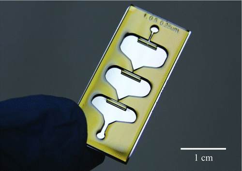
A complete microscale cascade impactor system is shown in . The system has dimensions of 3.3×1.4 cm2 (length × width). Three different impactors with just one stage (the first, second, or third stage) were individually manufactured to measure the collection efficiencies of the impactor. Next, to measure the overall particle losses in the system, two different impactors either with or without the impaction plates were fabricated.
3.3. Experimental
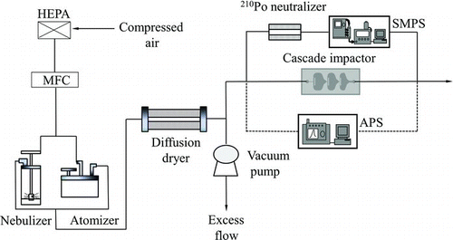
shows a schematic diagram of the experimental setup, including the particle generator, the microscale cascade impactor, and the measurement system. Compressed air filtered through a HEPA filter entered the Collision nebulizer (BGI Corp.) and atomizer (Model 9302, TSI Inc.) with flow rates of 12 L/min and 5 L/min, respectively. The nebulizer and atomizer were employed to aerosolize nanoscale (10–1000 nm) and micronscale (1.0–2.5 μm) particles simultaneously. A diffusion dryer was installed after the particle generation system to remove moisture from the aerosol stream. The aerosol stream entered the 210Po neutralizer (Grimm Corp.) at a flow rate of 0.5 L/min, and excess flow was vented to the atmosphere. The flow rate was controlled using a mass flow controller (FC-280SAV, Mykrolis). The electrical mobility diameters and aerodynamic diameters of the particles were measured by the scanning mobility particle sizer (SMPS; Model 3936, TSI Inc.) and the aerodynamic particle sizer (APS; Model 3321, TSI Inc.), respectively, upstream and downstream of the cascade impactor. Ammonium sulfate 10–700 nm in size (Junsei Inc., Japan) and polystyrene latex (PSL) particles 0.2–2.5 μm in size (Polyscience Inc., Warrington, PA, USA) were used as the test particles. The first and second stages of the cascade impactor were calibrated using PSL particles, and the third stage was evaluated using ammonium sulfate. The electrical mobility diameter could be converted to the aerodynamic diameter using the following equation (Peters et al. Citation1997),
EquationEquation (5) is valid when the mobility diameter is the same as the equivalent volume diameter (Kasper Citation1982). The dynamic shape factor of the PSL particle was unity and that of the ammonium sulfate was 1.03–1.07 in the experimental condition (Zelenyuk et al. Citation2006). When performing the conversion, the difference between the mobility diameter and the equivalent volume diameter was negligible because the dynamic shape factor of the ammonium sulfate is close to unity. The densities of each particle were 1.77 g/cm3 (ammonium sulfate) and 1.05 g/cm3 (PSL). The nebulizer and atomizer were used to aerosolize the ammonium sulfate and PSL particles, respectively. Particles were transported to the device using a polytetrafluoroethylene (PTFE) tube. To reduce the particle bounce effects, the microscale cascade impactor was spin-coated with silicon oil (KF-96, Shinetsu Corp.) at 3000 rpm for 45 s, yielding a thickness of 0.5–1.0 μm. The bounce effects were minimized for a silicon oil layer thickness greater than 0.5 μm on the impaction plate (Pak et al. Citation1992). The collection efficiency of a given particle size can be calculated as (Demokritou et al. Citation2002),
4. RESULTS AND DISCUSSION
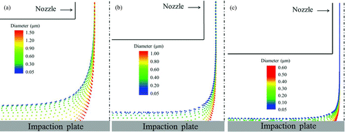
shows the calculated particle trajectories at each impaction stage. The cutpoint diameter of the first stage was 1.06 μm such that particles larger than 1.06 μm adhered to the impaction plate and particles smaller than 1.06 μm followed the air streamline. The cutpoint diameters at the second and third stages were calculated to be 0.55 μm and 0.26 μm, respectively. The numerical results informed the design of the actual microscale cascade impactor system.
The collection efficiency calculated from the experimental data was fit to a Boltzmann sigmoidal function,
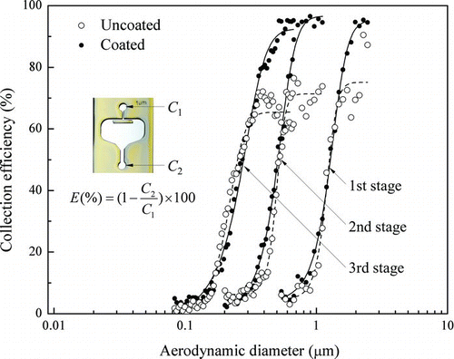
shows the collection efficiencies of the microscale cascade impactor at each stage. The particle number concentrations upstream and downstream of the individual stage are shown in the inset of . A comparison with the designed system showed that the measured cutpoint diameters were within 13% of the theoretical values. The dashed and solid lines indicate the collection efficiencies of the uncoated and silicon oil-coated microscale cascade impactors, respectively. The silicon oil-coated system displayed a sharper curve than the uncoated system because the coated system reduced the problems associated with bounce effects. At the first stage, where the second and third stages being not installed, the cutpoint diameters were 1.19 μm for both the uncoated and coated systems, similar to the designed values. In the uncoated system, the collection efficiency increased to 73% with increasing the aerodynamic diameter of the particle, and then decreased thereafter. Beyond a minimum value (62%), the collection efficiency again increased. This trend was attributed to the secondary collection of bounced particles (Pak et al. Citation1992). At the second stage, not the first and third stages installed, the cutpoint diameters were 0.52 μm and 0.51 μm for the uncoated and coated systems, respectively. The collection efficiency followed the same trend as was observed at the first stage due to the bounce effects and secondary collection on the impaction stage. At the third stage, not the first and second stages installed, the cutpoint diameters of both systems were 0.27 μm. Large differences in the collection efficiencies of the uncoated and coated systems were observed at the third stage due to the high velocity of the aerosol jet at the nozzle, which increased the elastic collision frequency between the particles larger than the cutpoint diameter and the device surfaces. summarizes the measured cutpoint diameters and the sharpness of the collection efficiency curve σ. At the three stages, the values representing the collection efficiency sharpness were 1.37, 1.39, and 1.47, respectively, which demonstrated the suitability of the present system as an inertial impaction system (Demokritou et al. Citation2004).
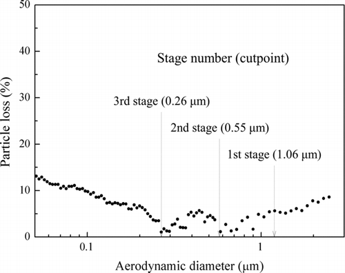
The overall particle losses, which are defined as the collection of particles caught at other parts of the device except for the impaction stage, were evaluated by measuring the collection efficiency without the impaction plates (Misra et al. Citation2002; Demokritou et al. Citation2004). shows the overall particle losses in the microscale cascade impactor system as a function of the aerodynamic diameter. The particle losses in the system were 5%–9% for particles larger than 0.2 μm and 9%–12% for particles smaller than 0.2 μm. Moreover, the particle losses for particles 1.0–2.5 μm in diameter were higher than those reported previously (Marple et al. Citation1991). The particle losses mainly occurred at three positions: the entrance region of the device, the acceleration nozzles at each stage, and the curved region of the device. As the particles entered the device (entrance region), they collided with the Si wafer surface, which acted as an unexpected impaction stage because the tube was positioned perpendicular to the aerosol stream direction in the microscale cascade impactor system. Our calculations predicted a cutpoint diameter at the entrance region of approximately 6.8 μm. This artifact can be reduced by increasing the tube diameter or inserting the tube parallel to the aerosol flow direction. The losses of particles 0.05–0.20 μm in diameter were the highest due to diffusional deposition in the system (Demokritou et al. Citation2004).
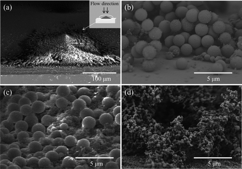
Particles adhesion at the impaction plate was visualized using SEM of each stage. shows a deposition pattern of particles on an impaction stage. As shown in , the deposited particles formed a mountain-shaped deposition pattern similar to that observed in conventional impactor systems (Wittmaack Citation2002). and c show the deposited particles at the first and second stages of the impaction zone, respectively. The images reveal particles larger than the cutpoint and some agglomerated particles smaller than the cutpoint. At the third stage, shown in , ammonium sulfate particles 200 nm in size (with an aerodynamic diameter of 260 nm) were deposited on the impaction plate.
5. CONCLUSIONS
A microscale cascade impactor system consisting of three stages was developed and evaluated. The microscale cascade impactor was fabricated using conventional soft lithography processes. At the three stages, the numerical 50% cutpoint diameters were 1.06, 0.55, and 0.26 μm, respectively. The experimental cutpoint values were 1.19, 0.51, and 0.27 μm, respectively. Deviations between the numerically predicted and experimental results were within 13%. To reduce the bounce effects and re-entrainment of particles, the devices were spin-coated with silicon oil. The sharpness of the collection efficiency curve was sufficient for use as an ultra-miniaturized cascade impactor system. The overall particle losses in the microscale cascade impactor were less than 10% for 0.2–2.5 μm particles and 9%–12% for particles smaller than 0.2 μm. The microscale cascade impactor system can be used as a personal bioaerosol detector because unlike conventional systems, it is ultra-compact, cost-efficient, highly accurate, and suitable for mass production. The bioaerosol detection can be achieved through a MEMS-based cartridge-type impaction plate and the discriminative chemical reaction between targeted bioaerosol and chemical compound on the impaction plate. Future work will focus on the development of cartridge-type impaction stages that can be separated easily from the devices.
Acknowledgments
J.S. Kang and K.S. Lee contributed equally to this work and should be considered co-first authors.
This work was supported by the Creative Research Initiatives (No. 2012-0000246) program of the National Research Foundation of Korea and by the KAIST High Risk High Return (HRHR) project.
REFERENCES
- Blachere , F. M. , Lindsley , W. G. , Pearce , T. A. , Anderson , S. E. , Fisher , M. Khakoo , R. 2009 . Measurement of Airborne Influenza Virus in a Hospital Emergency Department . Clin. Infect. Dis. , 48 ( 4 ) : 438 – 440 .
- Bush , R. K. and Portnoy , J. M. 2001 . The Role and Abatement of Fungal Allergens in Allergic Diseases . J. Allergy Clin. Immun. , 107 ( 3 ) : 430 – 442 .
- Demokritou , P. , Kavouras , I. G. , Ferguson , S. T. and Koutrakis , P. 2002 . Development of a High Volume Cascade Impactor for Toxicological and Chemical Characterization Studies . Aerosol Sci. Technol. , 36 ( 9 ) : 925 – 933 .
- Demokritou , P. , Lee , S. J. , Ferguson , S. T. and Koutrakis , P. 2004 . A Compact Multistage (cascade) Impactor for the Characterization of Atmospheric Aerosols . J. Aerosol Sci. , 35 ( 3 ) : 281 – 299 .
- Douwes , J. , Thoren , O. , Pearse , N. and Heederik , D. 2003 . Bioaerosol Health Effects and Exposure Assessment: Progress and Prospects . Ann. Occup. Hyg. , 47 ( 3 ) : 187 – 200 .
- Farsund , O. , Rustad , G. , Kasen , I. and Haavadsholm , T. V. 2010 . Required Spectral Resolution for Bioaerosol Detection Algorithms Using Standoff Laser-Induced Fluorescence Measurements . IEEE Sens. J. , 10 ( 3 ) : 655 – 661 .
- Hinds , W. C. 1999 . Aerosol Technology , New York : John Wiley & Sons .
- Huang , C. H. , Chang , C. S. , Chang , S. H. , Tsai , C. J. , Shih , T. S. and Tang , D. T. 2003 . Use of Porous Foam as the Substrate of an Impactor for Respirable Aerosol Sampling . J. Aerosol Sci. , 36 ( 11 ) : 1373 – 1386 .
- Huang , C. H. and Tsai , C. J. 2002 . Influence of Impaction Plate Diameter and Particle Density on the Collection Efficiency of Round-Nozzle Inertial Impactors . Aerosol Sci. Technol. , 36 ( 6 ) : 714 – 720 .
- Huang , C. H. and Tsai , C. J. 2003 . Mechanism of Particle Impaction and Filtration by the Dry Porous Metal Substrates of an Inertial Impactor . Aerosol Sci. Technol. , 37 ( 6 ) : 486 – 493 .
- John , W. 1999 . A simple Derivation of the Cutpoint of an Impactor . J. Aerosol Sci. , 30 ( 10 ) : 1317 – 1320 .
- Jung , J. H. , Hwang , G. B. , Park , S. Y. , Lee , J. E. , Nho , C. W. Lee , B. U. 2011 . Antimicrobial Air Filtration Using Airborne Sophora Flavescens Natural-Product Nanoparticles . Aerosol Sci. Technol. , 45 ( 12 ) : 1510 – 1518 .
- Jung , J. H. , Lee , C. H. , Lee , J. E. , Lee , J. H. , Kim , S. S. and Lee , B. U. 2009 . Design and Characterization of a Fungal Bioaerosol Generator Using Multi-Orifice Air Jets and a Rotating Substrate . J. Aerosol Sci. , 40 ( 1 ) : 72 – 80 .
- Kasper , G. 1982 . Dynamics and Measurement of Smokes. I Size Characterization of Nonspherical Particles . Aerosol Sci. Technol. , 1 ( 2 ) : 187 – 199 .
- Kauppinen , E. I. , Jaooubeb , A. V. K. , Hillamo , R. E. , Rantio-Lehtimaki , A. H. and Koivikko , A. S. 1989 . A Static Particle Size Selective Bioaerosol Sampler for the Ambient Atmosphere . J. Aerosol Sci. , 20 ( 7 ) : 829 – 838 .
- Keskinen , J. , Pietarinen , K. and Lehtimaki , M. 1992 . Electrical Low Pressure Impactor . J. Aerosol Sci. , 23 ( 4 ) : 353 – 360 .
- Lee , S. J. , Demokritou , P. , Koitrakis , P. and Delgado-Saborit , J. M. 2006 . Development and Evaluation of Personal Respirable Particulate Sampler (PRPS) . Atmos. Environ. , 40 ( 2 ) : 212 – 224 .
- Marple , V. A. 1976 . Impactor Design . Atmos. Environ. , 10 ( 10 ) : 891 – 896 .
- Marple , V. A. , Rubow , K. L. and Behm , S. M. 1991 . A Microorifice Uniform Deposit Impactor (MOUDI): Description, Calibration, and Use . Aerosol Sci. Technol. , 14 ( 4 ) : 434 – 446 .
- Misra , C. , Singh , M. , Shen , S. , Sioutas , C. and Hall , P. M. 2002 . Development and Evaluation of a Personal Cascade Impactor Sampler (PCIS) . J. Aerosol Sci. , 33 ( 7 ) : 1027 – 1047 .
- Moon , H. S. , Nam , Y. W. , Park , J. C. and Jung , H. I. 2009 . Dielectrophoretic Separation of Airborne Microbes and Dust Particles Using a Microfluidic Channel for Real-Time Bioaerosol Monitoring . Environ. Sci. Technol. , 43 ( 15 ) : 5857 – 5863 .
- Pak , S. S. , Liu , B. Y. H. and Rubow , K. L. 1992 . Effect of Coating Thickness on Particle Bounce in Inertial Impactors . Aerosol Sci. Technol. , 16 ( 3 ) : 141 – 150 .
- Peters , T. M. , Chein , H. , Lundgren , D. A. and Keady , P. B. 1997 . Comparison and Combination of Aerosol Size Distributions Measured with a Low Pressure Impactor, Differential Mobility Particle Sizer, Electrical Aerosol Analyzer, and Aerodynamic Particle Sizer . Aerosol Sci. Technol. , 19 ( 3 ) : 396 – 405 .
- Rader , D. J. and Marple , V. A. 1985 . Effect of Ultra-Stokesian Drag and Particle Interception on Impaction Characteristics . Aerosol Sci. Technol. , 4 ( 2 ) : 141 – 156 .
- Sengupta , A. , Brar , N. and Davis , E. J. 2007 . Bioaerosol Detection and Characterization by Surface-Enhanced Raman Spectroscopy . J. Colloid Interf. Sci. , 309 ( 1 ) : 36 – 43 .
- Singh , M. , Misra , C. and Sioutas , C. 2003 . Field Evaluation of a Personal Cascade Impactor Sampler (PCIS) . Atmos. Environ. , 37 ( 34 ) : 4781 – 4793 .
- Steele , P. T. , Farquar , G. R. , Martin , A. N. , Coffee , K. R. , Riot , V. J. Martin , S. I. 2008 . Autonomous, Broad-Spectrum Detection of Hazardous Aerosols in Seconds . Anal. Chem. , 80 ( 12 ) : 4583 – 4589 .
- Trunov , M. , Trakumas , S. , Willeke , K. , Grinshpun , S. A. and Reponen , T. 2001 . Collection of Bioaerosol Particles by Impaction: Effect of Fungal Spore Agglomeration and Bounce . Aerosol Sci. Technol. , 35 ( 1 ) : 617 – 624 .
- Tseng , C. C. and Li , C. S. 2005 . Collection Efficiencies of Aerosol Samplers for Virus-Containing Aerosols . J. Aerosol Sci. , 36 ( 5–6 ) : 593 – 607 .
- Wittmaack , K. 2002 . Impact and Growth Phenomena Observed with Sub-Micrometer Atmospheric Aerosol Particles Collected on Polished Silicon at Low Coverage . Atmos. Environ. , 36 ( 24 ) : 3963 – 3971 .
- Zelenyuk , A. , Cai , Y. and Imre , D. 2006 . From Agglomerates of Spheres to Irregularly Shaped Particles: Determination of Dynamic Shape Factors from Measurements of Mobility and Vacuum Aerodynamic Diameters . Aerosol Sci. Technol. , 40 ( 3 ) : 197 – 217 .
