Abstract
Particle charging by indirect photoemission may be an alternative to charging methods based on corona discharge or on bipolar charging by radioactive ion sources. An indirect charger using a low energy UV radiation is introduced and characterized in detail. Depending on the carrier gas, photoelectrons or ions formed by electron-attachment charge the particles by diffusion charging. The achieved charging efficiency is in the range of 20–70% for particle sizes of 20 to 100 nm. It can easily be modulated by a small voltage applied to the photoemitter. To achieve stable electron emission, glassy carbon with its very inert surface is used as photoemitter. Particle losses are very small. The charge distribution has been measured by a tandem DMA setup. The experimental results are compared with the theory of unipolar diffusion charging based on the Fuchs’ combination probability of ions with the particles. The charger characterization has been performed by carbon particles in a size range of 20–100 nm, produced by a spark discharge generator.
Copyright 2013 American Association for Aerosol Research
1. INTRODUCTION
For many techniques to measure size and concentration of submicron particles, as for example mobility analysis, it is necessary to charge the particles electrically. A number of ways to charge particles have been developed including unipolar and bipolar charging.
The most frequently used technique for bipolar charging is producing gas ions by a radioactive source (Kr-85, Ni-63, Am-241, Po-210). These ions then attach to the particles by diffusion. The main advantage of bipolar charging is that a charge equilibrium is established, which is independent of the ion concentration. This allows achieving a very well-defined charge distribution. The charging efficiency is limited, which has the advantage that the number of multiply charged particles is moderate and the disadvantage of reducing the detection limit. On the other hand, dealing with radioactive sources causes more and more problems, in particular for field measurements. Therefore, alternatives are investigated since very long time. Meanwhile X-ray ionizers are available (Han et al. Citation2003; Kaufman Citation2010) which are easier to handle, but still are subject to restriction in transport in some countries. Chargers based on bipolar electrical discharges have also been investigated (bipolar corona, Stommel and Riebel Citation2005, dielectric barrier discharge, Byeon et al. Citation2008) but so far with limited success. A comparison of different bipolar chargers can be found in Kallinger et al. (Citation2012). Bipolar charging is applied for differential mobility analysis in scanning devices (DMPS, SMPS).
Unipolar charging can be obtained on the one hand by directly ionizing the particles by irradiation with electromagnetic radiation (UV light), leading to the emission of electrons. This process (direct photoelectric charging) is strongly material dependent and can be used to selectively charge certain particle classes (Schmidt-Ott and Siegmann Citation1978; Burtscher et al. Citation1982).
If charging should be material-independent, unipolar ions can be produced by a corona discharge (silent electrical discharge). These ions attach to the particles by diffusion (unipolar diffusion charging) or assisted by an electrical field (field charging). Field charging is used in electrostatic precipitators, where charging and precipitation are achieved by the same field. For measurement purposes, usually diffusion charging is used. The charging occurs in a mainly field-free area.
Unipolar charging allows obtaining a higher efficiency than bipolar charging, but as a consequence this also leads to more multiply charged particles.
It is applied in the fast mobility analyzers (EEPS, FMPS, DMS500), where the parallel measurement of many channels by electrometers requires an efficient charging technique to achieve a reasonable detection limit.
Also, a number of particle sensors (diffusion charging sensors, EAD, NSAM, DiSC, etc.) make use of corona charging. More information can be found for example in Dhaniyala et al. (Citation2011) or Intra and Tippayawong (Citation2011).
Corona chargers are relatively simple, robust devices. Some drawbacks are that the corona always produces some ozone. To minimize ozone formation, carbon microfibers have been used for ion generation (Han et al. Citation2008). Depending on the carrier gas of the particles, the plasma of the corona discharge may act as a chemical reactor, producing undesired species, in some cases also additional particles. Many chargers need an electrical field to bring the ions into the charging zone that leads to losses for very small particles.
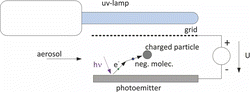
Here, we use a different approach for unipolar diffusion charging. A surface is irradiated with UV light of a photon energy higher than the ionization threshold of the surface, but below the threshold of the particles and that for ozone formation. Depending on the carrier gas the emitted photoelectrons remain free (in noble gases) or attach to gas molecules (if an electronegative gas like oxygen is available). In air, negative ions are formed within microseconds. These ions then attach to the particles by diffusion (). A very small DC-voltage U is applied between the photoemitter and a grid to assist electron escape from the emitter.
This technique (indirect photoelectric charging) allows a very soft ion production mainly without inducing undesired chemical reactions. To our knowledge, Bucholski and Niessner (Citation1991) introduced indirect photoelectric charging first. Later Oh et al. (Citation2004) used an indirect photoemission charger to investigate the effect of particle shape on the charging efficiency. Shimada et al. (Citation1997, Citation1999) used indirect photoemission to charge particles for electrostatic precipitation. Even if some earlier work exists, where this technique has been applied, it never has been investigated thoroughly. Here we will present a detailed characterization of an indirect photoemission charger with the purpose to substitute radioactive bipolar charger or corona chargers, e.g., used for producing a monodisperse aerosol by electrostatic classification.
2 BASIC CONSIDERATIONS
The photon energy of the UV light source has to be chosen such that it is above the ionization threshold of the photoemitter, but below the threshold for ozone formation and below the threshold, where particles start to emit electrons. Usually the latter restriction will be dominant for the upper limit. This leaves only a narrow window of photon energies. No materials exist that have a stable ionization threshold below about 4.5 eV, when exposed to air. Above little more than 5 eV, ambient air molecules start emitting electrons. As a result, the available range of wavelength is ca. 275–240 nm.
At ambient pressure, most photoelectrons will diffuse back to the emitter if the voltage U is zero or very small. The corresponding ion concentration will be low. The electron escape probability increases with increasing U, until all electrons escape. On the other hand, a high U will lead to a rapid precipitation of the electrons or ions, respectively. This reduces the ion concentration again. Therefore, the ion concentration will be low for very small and for high U, somewhere in between a maximum exists, where the charging efficiency also will have its maximum. A quantitative treatment will follow.
In carrier gases without electronegative molecules electrons remain free. Due to their very high mobility, their residence time is short, and the charge concentration will be low.
Once the electron/ion concentration is known, the product of concentration and residence time (N × t product) can be determined, which is directly related to the charging efficiency.
3 THEORETICAL CALCULATION OF PARTICLE CHARGING
The experimental results were compared with the theoretical considerations for unipolar diffusion charging described by Adachi et al. (Citation1985) using Fuchs’ combination probability of ions with the particles and the basic differential equations from Boisdron and Brock (Citation1970) in the case of unipolar diffusion charging:
[1]
[2]
In these equations, n0 denotes the number concentration of the uncharged particles, np the number concentration of the particles carrying p elementary charges, and nT particle number concentration in total. N specifies the ion concentration and βp the combination probability.
Assuming that the initial particles are uncharged, the analytical solution for the charged fraction of particles np/nT carrying p elementary charges can be found:
[3]
[4]
The combination probability βp has been determined using Fuchs’ limiting sphere theory (1963) whereupon the diffusion coefficient Dion, mean thermal velocity cion, and the mean free path of the ions λion in dry air have been calculated by following equations (Adachi et al. 1985).
[5]
[6]
[7] where k is the Boltzmann factor, Na the Avogadro number, T the temperature that was considered to be 300 K, and e the elementary charge. As we have been using dried air as carrier gas in our study, we assumed the formation of O−2 ions by electron attachment in a three-body reaction with oxygen or nitrogen molecules as third body (Davies Citation1983):
[8]
In the presence of CO2, further reactions can form heavier CO−4 ions as considered by Davies (Citation1983). Therefore, we set the molecular weight for the ions Mion = 76 g/mol and the ion mobility Zion = 2.3 × 10⁻⁴ m2/Vs (Davies Citation1983). In the experimental results, we used mainly the average number of elementary charges per particle, η, defined as follows:
[9]
4 EXPERIMENTAL SETUP
A prototype of an indirect charger has been built. Extended tests have been performed with carbon particles produced by a spark discharge generator; for some experiments, NaCl particles have been used.
4.1 Setup of the Indirect Photoemission Charger (IPC)
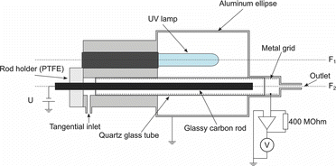
shows the indirect photoelectric charger, used for our experiments. A pen ray Hg low-pressure mercury lamp, emitting at 254 nm (ozone-free version, suppressing the 185-nm line) is applied. It has a lighted length of 45 mm. A glassy carbon rod with a diameter of 6 mm is used as electron emitter. Glassy carbon is used because it combines an ionization threshold in the desired window with a very inert surface. This is essential to achieve a stable electron emission. To keep the surface clean, the rod can be heated to a temperature of about 80°C by an electrical current through the rod. Lamp and emitter are placed in the focuses of an elliptical mirror. Thereby the light is focused onto the rod. The rod is placed in the axis of a quartz tube. A metal grid at the inner wall of the tube allows to apply an electrical voltage between the rod and the screen. The particle charging time is 0.45 s considering a flux of 0.3 lmin−1 and an inner diameter of the grid of 10 mm. We assume that charging takes only place along the illuminated length. The current of ions, arriving at the screen is measured by a current–voltage converter, having a sensitivity of 0.4 V/nA (400 MΩ feedback resistor). This amplifier keeps the grid virtually at ground potential.
We determined the ion concentration from the measured current by following consideration. The measured ion current through the grid is defined as follows:
[10]
The length L is the length of the UV irradiation, which is equal to the length of the lamp. The inner radius of the grid is substituted by r2. The drift velocity of the ions v can be calculated by the ion mobility Zion and the electrical field E.
[11]
The electrical field at r2 can be obtained by knowing the potential applied to the rod U and the radius of the rod r1.
[12]
Therefore, the ion concentration can be calculated by the following equation:
[13]
4.2 Setup to Determine the Average Number of Elementary Charges Per Particle
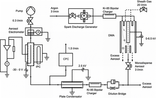
The experimental setup to determine the average number of elementary charges per particle is shown in . Particles are produced by a Palas GFG1000 spark generator, equipped with carbon electrodes. The generator is followed by a differential mobility analyzer to select one particle size class. These particles then pass through a Kr-85 charger. A plate condenser removes all remaining charged particles. The number concentration of the monodisperse, neutral particles nT, entering the IPC, is measured by a CPC. The charged particles npT downstream the IPC are measured by an aerosol electrometer (TSI3068). It was evaluated from the electrometer current IAEM and the aerosol flux q by the assumption of single charged particles (p = 1).
[14]
The average number of elementary charges per particle η can be calculated as follows:
[15]
To determine losses, the CPC may be connected also downstream the IPC. Loss measurements are performed with carbon particles from the spark generator and with NaCl particles produced by an atomizer. Losses are determined by comparing the concentration, measured with the CPC upstream and downstream the IPC.
4.3 Setup to Determine Multiple Charging
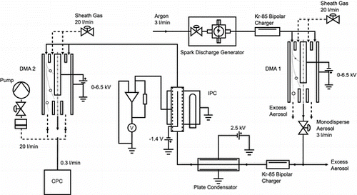
To determine the fraction of multiply charged particles, a tandem DMA setup is used (). As before monodisperse, neutral particles enter the IPC. At the outlet, a second DMA is placed that classifies the particles according to the number of charges they carry.
The shown setup delivers only the fraction of charged particles:
[16]
To consider also the fraction of uncharged particles following method was used for the calculation. The concentration measured by the aerosol electrometer npT with the setup described in Section 4.2 is defined as:
[17]
Knowing also the total number concentration nT, the concentration of the neutral particles can be calculated:
[18]
5 RESULTS
Experiments have been made with different carrier gas for the particles by mixing the argon stream of the spark discharge generator with the sheath gas of the DMA using dry air, nitrogen, and argon. As for most applications the carrier gas will be air, results with air are shown in detail, then a brief section for the other gases follows.
5.1 Dry Air
5.1.1 Average Number of Elementary Charges Per Particle
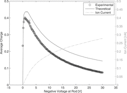
In the ion current and the average number of elementary charges per particle are plotted versus the voltage, applied at the rod. For low voltages the ion current is small, because most of the emitted electrons diffuse back to the rod. With increasing voltage the escape probability also increases, which leads to an increasing ion current (for more information on back diffusion probability of photoelectrons, see for example Radmilović-Radjenović et al. Citation2009). However, the increasing voltage also leads to a higher drift velocity of the ions, reducing the ion concentration and thus the N × t product, which is responsible for the average charge. For very low voltages the ion current is very small, for high voltage the ion residence time. As a result, the ion concentration and the average charge have a maximum occurring at ca. 1.4 V. For all following measurements, the rod voltage has been set to 1.4 V. The experiment and the theoretical calculation show the same trend. The theoretical average charge is about 4% larger than measured for 1.4 V. The difference between theory and experiment can be explained that the Fuchs’ model does not consider the particle losses. For increasing voltage the differentiation is increasing, which can be due to the effect of higher particle losses with increasing field strength.
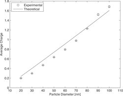
The average number of elementary charges as function of particle size is shown in . It is comparable to typical efficiencies obtained with corona chargers. Experimental and theoretical results fit very well considering again possible particle losses.
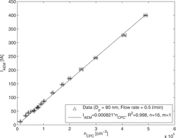
shows the current of charged particles versus their number concentration. The perfect linearity up to particle concentrations of 5 × 105 cm−3 shows that no saturation occurs up to high concentrations.
5.1.2 Losses
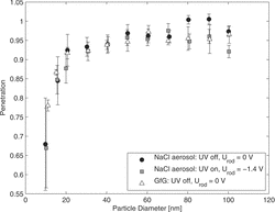
Particle penetration through the charger has been determined for NaCl particles (mainly spherical) and particles produced by the spark discharge generator (agglomerates). Results are plotted in . The difference observed, when UV lamp or rod voltage is turned on and off, is very small. This indicates that mainly diffusion losses are relevant, not electrostatic precipitation. For larger particles, losses are slightly higher in the case of agglomerates.
5.1.3 Multiple Charges
Multiple charges have been measured with a tandem DMA setup. shows the mobility spectrum measured with the second DMA, when 40-nm particles are selected with the first. The modes for singly (main peak) and doubly charged particles (mode on the right) are well visible. An additional mode on the left of the main peak is due to larger particles, leaving the first DMA doubly charged. No higher charges occur for this particle size. The experimental result has been fitted with a lognormal distribution for each mode to evaluate the contribution of each mode. The fraction of charged particles was calculated from the relative peak heights. The total contribution of charged and uncharged particles is plotted in . The results for particle sizes from 20 nm to 100 nm are summarized in .
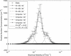
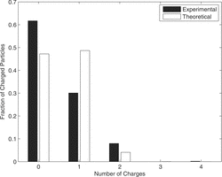
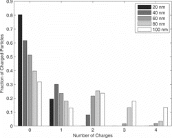
The results demonstrate for a particle size smaller than 40 nm the fraction of double charged particles is smaller than 8%. For 80–100 nm, the distribution gets very broad with particles carrying up to four elementary charges. In this range of particle size, one has to mention that the modes of the electrical mobility spectrum of multiple-charged particles appear only in a single peak. This makes it delicate for the fitting procedure to find the right solution.
From it can be estimated an extrinsic charging efficiency of the charger between 20% and 70%.
5.1.4 Particle Material
Experiments with particles from the spark generator and also with NaCl particles show a stable, reproducible performance of the charger. We also did some experiments with combustion aerosols, produced by a flame soot generator (AVL Particle Generator, AVL LIST GMBH, Austria). If the volatile fraction of these particles is removed by an evaporation tube or a thermodenuder, positively charged particles leave the charger. Obviously direct photoelectron emission from the particles dominates the charging process in this case.
5.1.5 Ozone Formation
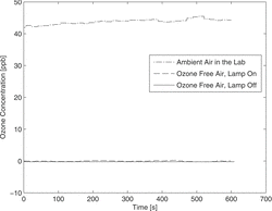
It was proved that the used pen ray Hg low-pressure mercury lamp is prohibiting the ozone formation by eliminating the 185-nm line with a quartz jacket. shows the ozone concentration after the charger measured with an ozone analyzer (O341 M, environment s. a., France). The measurement has been performed with a flux of 2 lmin−1 of particle and ozone-free air for turning on and off the UV light. For comparison, it is also shown the ozone concentration for ambient air in the lab. The results demonstrate no significant ozone production by the UV lamp. Moreover, we did not observe any undesired particles produced by the UV light in our experiments.
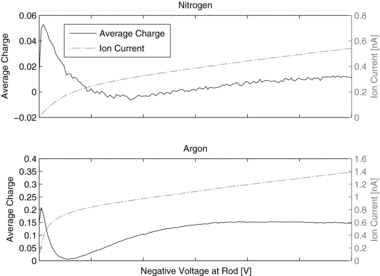
5.2 Argon and Nitrogen as Carrier Gas
Whereas emitted electrons immediately form ions in air, electrons remain free in pure noble gases and also in N2. This has a strong influence on particle charging. The very much higher mobility of free electrons leads to a short residence time. As a consequence, the same current leads to a much lower electron concentration, and the N × t product is much smaller. In addition, attachment coefficients are significantly different.
In contrast to ions, the electron mobility depends on the energy or the drift velocity of the electrons, respectively.
shows the measured grid current and the average number of elementary charges per particle as function of the rod voltage. The shape of the current–voltage relation is similar to the one obtained for air; it is mainly determined by the back-diffusion probability of electrons to the rod.
However, the average charge versus rod voltage is very different. The charging efficiency reaches a maximum already at a low voltage, even if the current still is low. With increasing voltage and increasing drift velocity the charging efficiency strongly decreases, as this was also the case for air. But now, after a minimum, the charging efficiency or the average charge per particle starts increasing again. This can be explained by a decrease in electron mobility with increasing drift velocity. The effect of the increasing current now is dominant, the charge concentration increases again. For both gases, the charging efficiency is very low compared to the result for air. Using data for the electron mobility versus drift velocity from Dutton (Citation1975) and electron attachment coefficients given by Romay and Pui (Citation1992), the shape of the efficiency-voltage curve can be explained.
The “negative” average charge, observed for nitrogen at voltages in the range of 5–12 V most probably is due to photoemission directly from particles, leading to positively charged particles. The indirect charging is very inefficient in this range, thus already a very small probability of electron emission from particles may be dominant.
6 CONCLUSIONS
Indirect photoemission allows a stable and well-defined material independent charging of ultrafine particles as long as the work function is higher than the photon energy of the light source. It can be an alternative to corona charging, having the advantage of low losses and no ozone formation. The charging efficiency is comparable to corona chargers. It can be varied by changing the lamp intensity or the voltage, applied to the photoemitter. This allows a very simple and effective control of the charging efficiency.
For particles from the spark discharge generator, and also for NaCl particles, no direct photoelectron emission is observed. However, for particles from a flame soot generator direct photoemission may be dominant. These particles either have a low enough ionization threshold to be ionized by the 254-nm light of the Hg lamp or are ionized by small amounts of light with higher photon energy, which is not completely absorbed by the bulb of the lamp. Similar effects have to be expected for other combustion aerosols, but also for metal aerosols. This is a restriction of the present setup, which has to be kept in mind.
It could be overcome by separating ion production and ion attachment. Ions could be produced in a particle-free gas flow, which is then mixed with the aerosol, as done already for other reasons for corona chargers. This would also allow using slightly higher photon energies and thus increase the charging efficiency. Experiments with such a setup are in progress. The configuration used by Shimada et al. (Citation1997), where a thin gold film is irradiated with UV light from one side and electrons are emitted to the other side, also could at least significantly reduce direct photoemission.
To run the charger with higher flow rates, the geometry could be changed to use quartz tubes with larger diameters and longer lamps to increase the residence time of the particles as well as the ion concentration in the charger.
The low pressure Hg lamp, used here has a limited live time and needs several minutes to warm up. Alternative light sources could be dielectric barrier discharge excimer lamps, which can be produced with a variety of wavelengths, have a very long lifetime and almost immediately reach their full intensity. In the near future UV LED's might be available, which would allow to build a significantly smaller charger.
REFERENCES
- Adachi, M., Kousaka, Y., and Okuyama, K (1985). Unipolar and Bipolar Diffusion Charging of Ultrafine Aerosol Particles. J. Aerosol Sci., 16:109–123.
- Boisdron, K., and Brock, J.R. (1970). On the Stochastic Nature of the Acquisition of Electrical Charge and Radioactivity by Aerosol Particles. Atmos. Environ., 4:35–50.
- Bucholski, A., and Niessner, R. (1991). Indirect Photoelectric Diffusion Charging of Submicron Aerosols. J. Aerosol Sci., 22:111–116.
- Burtscher, H., Scherrer, L., Siegmann, C.H., Schmidt-Ott, A., and Federer, B. (1982). Probing Aerosols by Photoelectric Charging. J. Appl. Phys., 53:3787–3791.
- Byeon, J.H., Ji, J.H., Park, J.H., Yoon, K.J., and Hwang, J. (2008). Charge Distributions of Aerosol Dioctyl Sebacate Particles Charged in a Dielectric Barrier Discharger. J. Aerosol Sci., 39:460–466.
- Davies, D.K. (1983). Measurements of Swarm Parameters in Dry Air. Theoretical Notes, Note 346. Westinghouse R&D Center, Pittsburgh.
- Dhaniyala, S., Fierz, M., Keskinen, J., and Marjamäki, M. (2011). Instruments Based on Electrical Detection of Aerosols. Aerosol Measurement - Principles, Techniques, and Applications. P. Kulkarni, P.A. Baron, and K. Willeke, ed., John Wiley & Sons, pp. 393–416.
- Dutton, J. (1975). A Survey of Electron Swarm Data. J. Phys. Chem. Ref. Data, 4:577–856.
- Fuchs, N.(1963). On the Stationary Charge Distribution on Aerosol Particles in a Bipolar Ionic Atmosphere. Pure and Appl. Geophys., 56:185–193
- Han, B, Kim, H.J., Kim, Y.J., and Sioutas, C. (2008). Unipolar Charging of Fine and Ultra-Fine Particles Using Carbon Fiber Ionizers. Aerosol Sci. Technol., 42:793–800.
- Han, B., Shimada, M., Choi, M., and Okuyama, K. (2003). Unipolar Charging of Nanosized Aerosol Particles Using Soft X-Ray Photoionization. Aerosol Sci. Technol., 37:330–341.
- Intra, P., and Tippayawong, N. (2011). An Overview of Unipolar Charger Developments for Nanoparticle Charging. Aerosol Air Quality Res., 11:187–209.
- Kallinger, P., Steiner, G., and Szymanski, W.W. (2012). Characterization of Four Different Bipolar Charging Devices for Nanoparticle Charge Conditioning. J. Nanoparticle Res., 14(6), . Article number 944.
- Kaufman, S.L. (2010). Aerosol Charge Conditioner. US Patent 7, 796, 727.
- Oh, H., Park, H., and Kim, S. (2004). Effects of Particle Shape on the Unipolar Diffusion Charging of Nonspherical Particles. Aerosol Sci. Technol., 38:1045–1053.
- Radmilović-Radjenović, M., Nina, A., and Nikitovic, Z. (2009). Monte Carlo Simulation of the Back-Diffusion of Electrons in Nitrogen. Nuclear Instruments and Methods. Phys. Res. B, 267:302–304.
- Romay, F.J., and Pui, D.Y. H. (1992). Free Electron Charging of Ultrafine Aerosol. J. Aerosol Sci., 23:679–692.
- Schmidt-Ott, A., and Siegmann, H. (1978). Photoelectron Emission from Small Particles Suspended in Air. Appl. Phys., 32:710–713.
- Shimada, M., Cho, S.J., Okuyama, K., Tamura, T., Adachi, M., and Fujii, T. (1997). Removal of Airborne Particles by a Tubular Particle-Removal Device Using UV/Photoelectron Method. J. Aerosol Sci., 28:649–661.
- Shimada, M., Okuyama, K, Inoue, Y, Adachi, M., and Fujii, T. (1999). Removal of Airborne Particles by a Device Using UV/Photoelectron Method under Reduced Pressure Conditions. J. Aerosol Sci., 30:341–353.
- Stommel, Y.G., and Riebel, U. (2005). A Corona-Discharge-Based Aerosol Neutralizer Designed for Use with the SMPS-System. J. Electrostatics. 63:917–921.