Abstract
We introduce a new electrical measurement technique for aerosol detection, based on pulsed unipolar charging followed by a non-contact measurement of the rate of change of the aerosol space charge in a Faraday cage. This technique, which we call “aerosol measurement with induced currents,” has some advantages compared to the traditional method of collecting the charged particles on either an electrode or with a particle filter. We describe the method and illustrate it with a simple and miniature (shirt-pocket-sized) instrument to measure lung-deposited surface area. Aerosol measurement by induced currents can also be applied to more complex devices.
Copyright 2014 American Association for Aerosol Research
THEORETICAL BACKGROUND
An electrical point charge Q in free space produces an electric field. The law of Gauss states that the volume integral of the space charge divided by the permittivity of vacuum is equal to the surface integral of the electric field for any surface surrounding this charge:
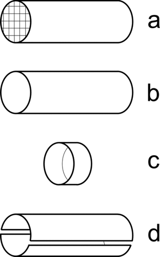
If the charge Q is placed inside a grounded conductive container (a “Faraday cage”), the electric field outside of the Faraday cage is shielded by the Faraday cage (![]() outside of the cage). Applying the law of Gauss, if we construct a surface surrounding the cage, the right-hand side of Equation (1) is zero, therefore, there must be an equal and opposite charge Q′ on the cage, Q′ = −Q. In electrostatics, this charge is known as the “image charge”. If the cage is semi-open, some of the field lines of the charge can reach the surrounding space, and the charge on the cage is reduced by a geometry-dependent factor, Q′ = −cQ (c∈[0, 1]), but nevertheless it is proportional to the charge in the cage. The magnitude of c is related to the degree of openness of the cage. Some examples that are relevant for our purpose are given in .
outside of the cage). Applying the law of Gauss, if we construct a surface surrounding the cage, the right-hand side of Equation (1) is zero, therefore, there must be an equal and opposite charge Q′ on the cage, Q′ = −Q. In electrostatics, this charge is known as the “image charge”. If the cage is semi-open, some of the field lines of the charge can reach the surrounding space, and the charge on the cage is reduced by a geometry-dependent factor, Q′ = −cQ (c∈[0, 1]), but nevertheless it is proportional to the charge in the cage. The magnitude of c is related to the degree of openness of the cage. Some examples that are relevant for our purpose are given in .
The different cage variants differ in their degree of openness: in , the cage is completely closed and c = 1; in , the ends of the tube are open, and a small part of the field can escape so that c is just a bit smaller than 1; in , a large part of the field lines escape from the cage and c ≪ 1; finally, in , each of the two segments of the tube sees the same signal by symmetry for a uniformly distributed space charge, and therefore c is two times smaller than in case b) for each of the two segments.
The image charge on the Faraday cage is thus always proportional to the space charge in the cage, regardless of geometry. When the space charge is a function of time, then the image charge on the cage also is a function of time. Since the cage is grounded, a current must flow between ground and cage which is induced by the space charge inside the cage. This induced current can be measured with an electrometer, and again, it is proportional to the rate of change of the space charge inside the cage. This is the basis for our new method for aerosol detection.
FIG. 1 (a) Tube with length L and radius R where L ≫ R, and with grids on both ends, (b) tube with L ≫ R, (c) ring with L ≪ R, and (d) the tube of (b) split into two equal segments.
Induced Currents as a Nuisance in Traditional Aerosol Instruments
There are several aerosol sizers that use a unipolar charger followed by multiple detection stages to measure a more or less finely resolved particle size distribution; examples for commercially available instruments are the electrical low pressure impactor (Dekati ELPI), the fast mobility spectrometers (Cambustion DMS500, TSI EEPS/FMPS), and the diffusion size classifier (Matter Aerosol DiSCmini). In each stage, a fraction f D of the charged aerosol is deposited on an electrometer, and thus detected as a deposited current I D, while the uncaptured rest, a fraction 1 − f D, passes through to the next stage; in the ELPI and the DiSC a final filter stage captures all remaining particles. In all these instruments, the uncaptured fraction of charged particles induces an image charge in the stages that it passes through. Under steady-state conditions, this is irrelevant; however, when the aerosol concentration changes rapidly over time, this leads to induced currents I I which are measured in the instrument in addition to the currents due to the deposition of charged particles. Under such circumstances, the electrometer measures the current I given by
This problem has been recognized by instrument manufacturers and has either been at least described, or mitigated in different ways: in the ELPI manual (Dekati Citation2008), negative current values due to induced currents are described, however, no solution for the problem is presented. In the new ELPI+ instrument, the impactor stages were redesigned such that the stage volume is smaller, thereby reducing (but not eliminating) the induced currents seen by the individual stages. In the original diffusion size classifier, an induction stage was used to measure I I prior to the first instrument stage to correct for the induced currents (Fierz et al. Citation2008), whereas in the later miniature version of the instrument (Fierz et al. Citation2011), the induced current is derived from the time derivative of the filter stage signal. In a patent related to the DMS500 (Reavell and Collings Citation2002), three different strategies are described to deal with the induced currents:
| i. | The use of a grounded screening electrode just in front of the electrometers, to avoid the occurrence of an image charge (which is what is used in the actual instrument). | ||||
| ii. | The use of a mathematical algorithm to correct for the image-charge-induced current, using time derivatives of the currents of later stages. | ||||
| iii. | The use of additional sense electrodes to measure only the induced current, which then is subtracted from the collecting electrodes. | ||||
So far, instrument manufacturers have thus dealt with the induced currents due to rapidly changing aerosol concentrations by trying to suppress the induced current term I I, either by reducing space charges seen by the stages, by preventing it from occurring at all by shielding the stages, by measuring it in a separate stage and compensating for it, or by correcting for it using time derivatives from later stages. These measures all improve the situation, but no correction is perfect, and induced currents remain problematic in traditional aerosol instruments, at the very least in the sense that they complicate the instruments or data inversion algorithms used.
Using Induced Currents
In this article, we propose a radically different solution: instead of viewing the induced current as a nuisance that has to be suppressed or compensated for, we apply it as a new method for aerosol measurement and call this an aerosol measurement by induced currents. This idea is in itself not strictly new: the fact that charges on particles can induce currents in ring-shaped sensing electrodes has been recognized earlier; however, this idea was first only applied to the measurement of the number of charges on single coarse particles (Gajewski and Szaynok Citation1981), and later to the measurement of the flow speed of a discontinuous dust-laden flow (Gajewski Citation1983). Induced currents were used to measure the number of charges on single particles in the size range of 4–20 μm (Vercoulen Citation1995); for smaller single particles, the method was not sensitive enough. Thus, up to now sensing electrodes for induced currents appear to have been restricted to the measurement of naturally occurring charges on single (micron-sized) particles. In contrast, we propose a method for measuring currents induced by an ensemble of initially uncharged particles.
In our new method to use induced currents for aerosol measurements, we view I I as the signal to use, whereas we want to get rid of I D. For this, two conditions have to be met:
| 1. | To get rid of I D, the sensing electrode should no longer capture any particles. This is easy, as normally an effort has to be made to collect the particles: by high electric fields (in the fast mobility spectrometers), low-pressure impaction (ELPI), or fine diffusion screens (DiSC). By using a simple sensing electrode as shown in , such as a tube with coarse mesh screens at inlet and outlet, or a tube without such screens, or a simple plate in a flow channel (similar to ), induced currents can readily be detected without collecting the particles. A very small fraction of the particles will still deposit on the sensing electrode by diffusion and produce a small current I D, which with proper design (electrode geometry, flow rate) is negligible compared to I I. | ||||||||||||||||||||||
| 2. | To measure the induced current I I, we must make sure that it also exists under static conditions, i.e., when aerosol concentrations do not change. This is not the case in traditional instruments, where no induced currents appear under static conditions. We must therefore artificially introduce a nonstatic space charge on the aerosol even under static aerosol concentrations. This can be achieved in many different ways, for example:
| ||||||||||||||||||||||
Versions (a) and (c) both produce well-defined charge clouds; version (a) needs a fast and stable control loop for the charger, whereas version (c) needs a high-voltage electrostatic precipitation unit. Version (b) appears less promising to us, as it produces less well-defined charge clouds. We chose to implement version (a) in the device described in the next section.
Implementation in a Personal Monitoring Device
For illustration, we present the simplest possible instrument based on our new concept. It is designed to measure the total current that is transferred to the aerosol by the unipolar charger, i.e., it is a simple diffusion charging (DC) instrument like the Matter Engineering LQ1-DC, the Ecochem 2000, or the TSI models EAD/NSAM/Aerotrak 9000. We will not give a full characterization of the instrument here and restrict the discussion to the differences to traditional DC instruments.
The signal of our instrument can be interpreted and calibrated to lung-deposited surface area (LDSA), just as with standard DC instruments. LDSA is a potentially health relevant metric (Shin et al. Citation2007; Wilson et al. Citation2007). In principle, this calibration can be performed both for the alveolar deposition (A-LDSA) as well as for the tracheobronchial deposition (TB-LDSA); we calibrate our instrument to the alveolar LDSA. We describe our calibration procedure in a bit more detail to suggest a standard procedure that can be used by others to calibrate diffusion chargers for LDSA, since so far, no such standard procedure seems to have been proposed anywhere. Since this calibration procedure is not directly related to measurement of aerosols by induced currents as such, we give the details of the calibration in the Appendix.
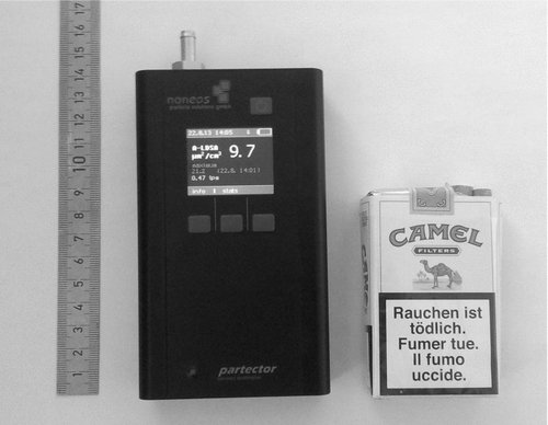
A scheme of the instrument is given in , and the final instrument, which we call the partector, is shown in . The only visible difference to traditional diffusion charging instruments is the replacement of the filter in the electrometer with the Faraday cage. The absence of a filter means that no filter exchanges are necessary, i.e., the maintenance intervals should be longer than in traditional filter-based instruments.
FIG. 2 Scheme of our new instrument. Similar previous instruments use a filter to capture the particles in a Faraday cup electrometer, whereas we use an open Faraday cage.

The instrument dimensions are 134 × 78 × 29 mm (without the tube connector visible in ), and it weighs 440 g. Power consumption is below 1 W so that it achieves a battery life of over 12 h with a new Li:ion battery (which will however degrade over time). We used an aluminum unibody design as in our last development, the miniDiSC (Fierz et al. Citation2011), but changed many details in key components.
The unipolar charger was redesigned so that the corona wire can be accessed much more easily for cleaning via a hatch in the back of the instrument, which can be opened by removing two screws.
The electrometer was designed to be an order of magnitude faster than in the miniDiSC with a 3-dB-cutoff of 8 Hz instead of 0.76 Hz. This is necessary to measure the short current pulses properly. Increasing the electrometer amplifier bandwidth comes at the price of increasing electrometer noise; the noise scales with the square root of the bandwidth. Typical noise levels calculated as the standard deviation of 10 Hz electrometer values are around 0.75 fA compared to about 0.15 fA for one-second values in the miniDiSC. The increased bandwidth accounts for a factor of ![]() = 3.2 of the noise increase instead of the observed factor of 5; the remaining discrepancy comes from the smaller feedback resistor that we use now to increase the measurement range, which leads to larger Johnson noise.
= 3.2 of the noise increase instead of the observed factor of 5; the remaining discrepancy comes from the smaller feedback resistor that we use now to increase the measurement range, which leads to larger Johnson noise.
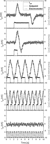
FIG. 4 Electrometer signal with 50 nm NaCl particles of a concentration of 1.7*104 pt/ccm (gray) and charging current (black) for different pulse settings.
The instrument's battery is charged directly over USB and therefore needs no separate power supply when connected to a PC; also, standard USB battery packs can be used to extend battery life to up to 72 h very easily.
The Faraday cage in the instrument consists of a tube with a volume of 6.0 cm3, the flow rate chosen is 500 ml/min, or 8.3 cm3/s. Assuming plug flow, the residence time of the aerosol in the Faraday cage is thus 0.7 s. By default, the charger is pulsed with a pulse period of 2 s and a duty cycle of 50%, i.e., a charge pulse lasts 1 s; however, these settings are software-selectable.
The diffusion losses in the tube acting as Faraday cage can be calculated as a function of the particle diameter; we get 2.8% (10 nm), 1.2% (20 nm), 0.4% (50 nm), and 0.1% (200 nm). Particles lost by diffusion in the tube will produce a deposited current I D, but as can be seen from the calculation, this is practically negligible (below 1% for particles larger than 25 nm) compared to the induced current I I.
Experimental Verification of the Measurement Principle
–e show different electrometer signals recorded by the instrument, along with the charging pulses that produced the signals, for a quasi-monodisperse NaCl aerosol (N = 1.7·104/ccm, d = 50 nm). In , we used a pulse period of 9 s and a duty cycle of 44%, which gives a charge pulse with a duration of 4 s. This leads to a positive pulse on the electrometer when the rising edge of the charge pulse enters the detection tube, followed by a negative pulse 4 s later, when the trailing edge of the pulse leaves the tube again. In between, the charge in the tube is constant, and thus the electrometer signal in between the pulses is essentially zero (except for noise). In , the pulse period remains at 9 s, but the duty cycle is reduced to 11%, i.e., the charge pulse now has a duration of 1 s. Now, the negative pulse follows immediately after the positive pulse, and for the remaining time, there is only a noise signal left. In , the pulse period is reduced to 2 s, and the duty cycle set to 50%; the pulses are again 1 s in duration, but follow each other much faster. This leads to a periodic, nearly harmonic signal. In , the pulse period is reduced to 1 s, while the duty cycle remains at 50%. The amplitude of the electrometer signal is reduced a bit. In , the pulse period is reduced to 0.5 s, and the electrometer signal nearly disappears. The results shown in –e can be interpreted easily: if the charger is pulsed too rapidly, then a new charge pulse will enter the tube while the previous pulse is still leaving the tube, so that the net change in the tube space charge is zero, and thus the electrometer signal disappears. From , it is clear that there is an optimum in terms of the charger pulsing—if too few pulses are produced (4a, 4b), then the electrometer signal is zero for long periods of time, i.e., there is no information in the signal during these periods. If the charger is pulsed too rapidly (4d, 4e), then subsequent pulses interfere with each other in the detection volume. In the case of optimal pulsing (4c), the electrometer signal always carries information without losing amplitude due to interference. The operating conditions of are also those finally implemented in our device.
A noteworthy detail is that—if c ≅ 1 for the Faraday cage—the electrometer signal during the influx of charge in the cage is essentially identical to that of a traditional filter-based diffusion charging instrument: the current flowing into the cage is equal to the current that is traditionally captured on a filter. When the charge cloud is flowing out of the cage, the sign of the electrometer signal is reversed, and therefore the signal amplitude measured by the electrometer is twice (or more precisely: 2·c times) the steady-state signal measured in the traditional filter-based instrument.
The resulting signal can now be evaluated in terms of its amplitude with a suitable algorithm. The straightforward attempt to evaluate peak–peak amplitudes over one pulse period is strongly influenced by noise on the signal. We therefore implemented a lock-in type algorithm, which detects the signal amplitude at the frequency f p of the unipolar charger pulses. Essentially, this algorithm acts as a bandpass filter, rejecting noise at lower and higher frequencies than f p. The bandwidth of the pass band of this filter can be decreased by applying it to a longer time interval (more pulses); however, this comes at the price of a lower time resolution. As a compromise, we ended up evaluating two pulse periods (4 s) by default, with the option of evaluating only one pulse period for better time resolution at the cost of higher noise.
It is worth noting that any algorithm to evaluate an amplitude can only give non-negative results. Therefore, a pure noise signal will appear as a (hopefully small) amplitude. This means that the instrument will have a non-zero noise floor, in contrast to the standard filter instrument, where the average of the noise signal can cancel out to zero.
To achieve a maximal time resolution, the pulses have to be made as fast as possible, however, as we have already seen, they can only be so fast that they do not interfere with each other in the detection zone. This means that flow rate, detection volume, and time resolution of this type of instrument are interconnected and cannot be changed at will. For a given detection volume, the time resolution can still be increased by increasing the flow velocity, which allows faster pulsing of the charger.
The Effect of Pre-Existing Charges
For one standard DC instrument, the TSI NSAM, which uses a positive unipolar charger, the effect of pre-existing charges on the aerosol has been investigated (Qi et al. Citation2009). For initially neutral and negatively charged particles, the final charge state is identical, whereas the final positive charge is a bit higher for initially positively charged particles. The final charge state—which is what the NSAM measures—is therefore nearly independent of the pre-existing charge. In contrast, our instrument measures differences in space charge, i.e., it measures the charge transferred to the aerosol, and not the final charge state. For initially neutral aerosol, this is the same thing; however, for initially negatively charged aerosol our instrument will give a too high LDSA value (since the charge difference is larger), and for initially positively charged aerosol it will give a too low LDSA value. Our proposed method is therefore less robust for pre-charged aerosols than the traditional filter-based collective method. Another alternative to filter-based particle collection, the escaping current technology (Rostedt et al. Citation2009), suffers from the same problem.
One way to overcome the difficulties with the pre-existing charge is to use a pulsed bipolar charger, which alternately charges the particles positively and negatively. This would give a nearly constant charge difference independent of the initial charge state of the aerosol, and it would also increase the signal amplitude by a factor of two. However, the charger electronics would be considerably more complex, and therefore we did not implement this idea in our instrument.
INSTRUMENT PERFORMANCE: MEASUREMENT RANGE
In , the peak–peak–amplitude of the electrometer signal is about 14 mV. This corresponds to a displayed LDSA of 37 μm2/cm3. The amplifier can measure up to ±4096 mV, or a peak–peak value of 8192 mV. Therefore, the maximal LDSA that can be measured is approximately 20,000 μm2/cm3. This value corresponds to about 8 × 10⁶ particles/cm3 for a particle diameter of 50 nm.
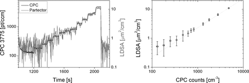
The lowest measurable signal can be deduced from , which compares the LDSA reported by the partector with the particle number from a CPC for low concentrations of 50 nm NaCl particles. The monodisperse particles were produced with a nebulizer followed by a dryer and a DMA, then they were neutralized and diluted with a rotating disk diluter. The partector was operating in its standard mode, with an internal time resolution of 4 s. Even without particles, the partector measures about 0.5 μm2/cm3, which for 50 nm particles corresponds to about 200 particles/cm3. Following the usual convention, the limit of detection is 3× the noise amplitude, i.e., about 1.5 μm2/cm3, which corresponds to about 600 pt/cm3 of a diameter of 50 nm. This can be compared with traditional filter-based diffusion charging instruments: Based on instrument noise alone, the lower limit of detection in the miniDiSC is about 0.5 μm2/cm3, and for the TSI NSAM about 0.8 μm2/cm3 (Dhaniyala et al. Citation2011). An additional error may occur if the electrometer zero offset drifts, which is not the case in our device. In conclusion, as a result of the noise-rejecting lock-in technique, the limit of detection in the partector is not much worse than in traditional instruments, despite the lower flow and the higher raw electrometer noise.
FIG. 5 Determination of lower detection limit with 50 nm NaCl particles. Left: time series of signals measured by CPC and partector for decreasing dilution. Right: averaged values over each concentration step. The line is a guide to the eye. The partector signal deviates from the 1:1 line for low concentrations due to instrument noise.
The overall measurement range is thus around 2–20,000 μm2/cm3, which is well matched to both ambient air as well as typical workplace conditions, and which gives a large dynamic range of 1:10,000.
INSTRUMENT PERFORMANCE: DRIFTING ZERO OFFSET
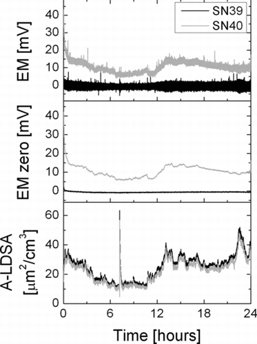
Electrometers always exhibit a zero offset, which is usually at least temperature-dependent and may also be influenced by other environmental variables, such as relative humidity. Therefore, in all electrometer-based aerosol instruments, an electrometer zeroing procedure is implemented, and recommended (or automatically performed) after warm-up of the instrument, or periodically for long-term measurements. The use of induced currents for aerosol detection removes the necessity for such zero offset measurements, as is demonstrated in . It shows the raw electrometer signal and the computed LDSA of two instruments sampling ambient air during round-robin testing of a batch of instruments. In the instrument with serial number 40, the insulator was not properly cleaned, and the electrometer zero offset exhibits a drift (which is not present in normal instruments, and disappeared after proper cleaning of the insulator in this instrument). Nevertheless, since the offset drift is slow compared to the pulsed signal, it is invisible in the calculation of the LDSA—by measuring only the amplitude of the AC component of the electrometer signal, a slowly drifting DC offset is completely suppressed.
Although the drifting zero offset had no real influence on the LDSA measurement in this case, it nevertheless is an indication that something is wrong with the instrument. By evaluating the average electrometer signal (i.e., by applying a low-pass filter to the signal with a cutoff frequency below the charger pulse frequency), it is possible to monitor the zero offset continuously, and to display a service warning if it drifts too much.
It is also noteworthy that the electrometer zero offset in our instruments needs a few minutes to settle after the instrument has been turned on. Nevertheless, since this drift during the warm-up phase is slow, a reliable measurement is possible already a few seconds after startup, whereas in traditional electrometer-based instruments, warm-up periods of several minutes are usually necessary.
CONCLUSIONS AND OUTLOOK
In this article, we have demonstrated that it is possible to use pulsed charging of aerosols followed by detection of induced currents as a new aerosol measurement technique, and we have applied the principle to build a miniature aerosol detector. To conclude, we compare our proposed new aerosol measurement method with traditional collecting methods—what are the advantages and the drawbacks of this new idea?
Starting with the drawbacks, the charger has to be more closely controlled to achieve the rapid pulsing necessary for our concept to work. Furthermore, if there is a pulse-to-pulse variability in the charger's ion pulses, this directly translates into instrument noise. Also, due to the pulsing, the time resolution is given by one pulse period (for our instrument: 2 s), which cannot be changed easily, since the instrument flow rate, Faraday cage size, and pulse period are interconnected. Since an AC amplitude is evaluated, a non-zero baseline noise appears even for particle-free air, so our instrument is a bit less sensitive than traditional diffusion charging instruments. Finally, our instrument is influenced more by pre-existing charges on the aerosol than traditional filter-based diffusion charging instruments, a shortcoming which could be overcome by the use of a pulsed bipolar charger.
Of course, there are also advantages: the electrometer zero offset is irrelevant for the measurement, allowing a measurement with practically no warm-up time and allowing an online “insulator health check” during the measurement. Due to the contactless measurement, there is no need for a particle filter to be exchanged, which means that service intervals are potentially longer, and the pressure drop over the instrument can be very small, i.e., the pump or blower needs very little power to generate the air flow in the instrument. Finally, it is easy to build miniature instruments based on this measurement principle: in our implementation, the “heart” of the instrument, the detection tube, only has a volume of 6 cm3.
As an outlook, a further interesting aspect of the induced current detection is the contactless measurement of the particles; this means that the particles are still available after passing through the detection volume. It is thus easy to imagine extensions of the simple instrument demonstrated here—for example, the charged particles can be collected on a TEM grid after the detection volume by means of a strong electric field. The time necessary to collect a suitable amount of particles on the grid can be deduced from the measured signal from the detection volume. Another possible extension is the use of two or more detection volumes in series, coupled by size-selective deposition stages (e.g., diffusion grids, electrostatic precipitators, impactors). By evaluating the signals of two detection volumes simultaneously, the average particle diameter and particle number can be deduced (similar to the Matter Aerosol DiSCmini, or the Grimm nanoCheck); using more detection volumes would allow a finer resolution of the particle size distribution.
REFERENCES
- Burtscher , H. and Schmidt-Ott , A. 2004 . Verfahren und Vorrichtung zur Messung der Anzahlkonzentration und des mittleren Durchmessers von in einem Trägergas suspendierten Partikeln . EP 1655595
- Dekati . 2008 . ELPI User Manual ver 4.10 , Dekati Ltd., Kangasala, Finland .
- Dhaniyala , S. , Fierz , M. , Keskinen , J. and Marjamäki , M. 2011 . “ Instruments Based on Electrical Detection of Aerosols ” . In Aerosol Measurement: Principles, Techniques, and Applications , (3rd ed.) , Edited by: Kulkarni , P. , Baron , P. A. and Willeke , K. John Wiley & Sons, Inc., New York .
- Fierz , M. , Burtscher , H. , Steigmeier , P. and Kasper , M. 2008 . Field Measurement of Particle Size and Number Concentration with the Diffusion Size Classifier (DiSC) . SAE 2008-01-1179.
- Fierz , M. , Steigmeier , P. , Houle , C. and Burtscher , H. 2011 . Design, Calibration and Field Performance of a Miniature Diffusion Size Classifier . Aerosol Sci. Technol. , 45 : 1 – 10 .
- Gajewski , J. B. 1983 . Inductive Non-Contact Method for Measuring a Velocity . J. Phys. E: Sci. Instrum., , 16 : 622 – 624 .
- Gajewski , J. B. and Szaynok , A. 1981 . Charge Measurement of Dust Particles in Motion . J. Electrostat., , 10 : 229
- Qi , C. , Asbach , C. , Shin , W. G. , Fissan , H. and Pui , D. Y. H. 2009 . The Effect of Particle Pre-Existing Charge on Unipolar Charging and Its Implication on Electrical Aerosol Measurements . Aerosol Sci. Technol., , 43 : 232 – 240 .
- Reavell , K. S. and Collings , N. 2002 . Methods to Improve Electrostatic Particle Measurement . UK Patent GB 2374671A
- Rostedt , A. , Marjamäki , M. , Yli-Ojanperä , J. , Keskinen , J , Janka , K. , Niemelä , V. and Ukkonen , A. 2009 . Non-Collecting Electrical Sensor for Particle Concentration Measurement . Aerosol Air Qual. Res., , 9 : 470 – 477 .
- Shin , W. G. , Pui , D. Y. H. , Fissan , H. , Neumann , S. and Trampe , A. 2007 . Calibration and Numerical Simulation of Nanoparticle Surface Area Monitor (TSI Model 3550 NSAM) . J. Nanopart. Res., , 9 : 61 – 69 .
- Vercoulen , P. H. W. 1995 . Electrostatic Processing of Particles , TU Delft . PhD Thesis
- Wilson , W. E. , Stanek , J. , Han , H.-S. , Johnson , T. , Pui , D. Y. H. , Turner , J. , Chen , D.-R. and Duthie , S. 2007 . Use of the Electrical Aerosol Detector as an Indicator of the Surface Area of Fine Particles Deposited in the Lung . J. Air Waste Manage. Assoc., , 57 : 211 – 220 .
APPENDIX: CALIBRATION FOR LUNG-DEPOSITED SURFACE AREA
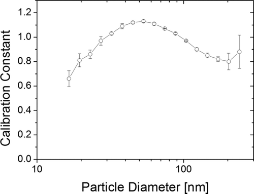
The calibration of our instrument is performed in a standard setup: NaCl particles are generated in a nebulizer, size-selected in a DMA, neutralized in a radioactive neutralizer and then split between a CPC and the partector. The partector calculates an amplitude-related factor (with an arbitrary unit), which is compared to a theoretic A-LDSA calculated from the ICRP 1994 model, particle diameter, and the CPC count. For each particle size, we get a specific calibration factor to relate A-LDSA to the amplitude of the electrometer signal. This size-dependent calibration factor for one such calibration run is given in Figure A1; it is very similar to the corresponding curve of the miniature diffusion size classifier (Fierz et al. Citation2011).
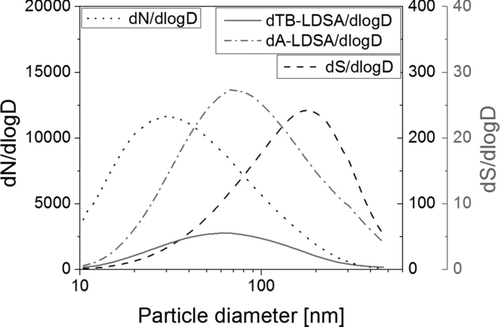
From Figure A1, it is obvious that the calibration factor is a function of particle size, however, the size dependence is rather weak. Nevertheless, due to the size dependence of the calibration factor, a choice has to be made: given the result in Figure A1, what should the overall calibration factor used in the instrument be? A straightforward approach would be to take an average of all values, which in this case would be 0.95; but then the result depends on the size range for which the instrument is calibrated. We use another approach taking typical ambient aerosols as a guideline: from the SMPS dataset of 2008 from the urban background air pollution monitoring station of the Swiss air quality network NABEL in Zürich we calculated an average particle size distribution for the year 2008. Next, we calculated the surface area distribution under the assumption of spherical particles, and from this, the lung-deposited fractions for the alveolar (A) and the tracheobronchial (TB) regions of the lung. The result of this calculation is shown in Figure A2.
The number size distribution has a maximum just below 30 nm, whereas the surface area size distribution has its maximum around 200 nm. If we look at the lung-deposited fractions (A and TB), we see that their maximum is at around 70 nm, however the distribution has a “fat tail.” One can argue that the instrument should work best for such a typical ambient aerosol and choose to calibrate it such that its size-dependent calibration constant should be weighted by the typical ambient aerosol at that size:
If we do this weighted calculation, we get a calibration constant of 0.99 in this case, which corresponds to the size-dependent calibration factor at about 95 nm. To simplify matters, and to suggest a standardization procedure for LDSA calibration that can also be used by others, we propose to use the size-dependent calibration value at 100 nm in the future, which, for the curve in Figure 8 is 0.98. Returning to Figure A1, we can also see that the calibration constant at 100 nm is approximately in the middle of the range of possible calibration constants, and therefore an acceptable choice.
Particle charging, and thus the calibration constant, also depend on particle material and morphology, but only weakly (Dhaniyala et al. Citation2011). Nevertheless, a standardized calibration procedure should also specify these particle properties for a better comparability between instruments of different manufacturers.

