
Abstract
We present and characterize a versatile device for studying the controlled interaction of free nanoparticles with supersaturated vapors. It utilizes an rf-ion trap for storing a cloud (>108 particles) of singly charged nanoparticles in the sub 10-nm size regime and combines it with a static supersaturation chamber operating at low pressure in free molecular flow regime. This allows for the stable production of a homogeneous zone of variable saturation that can reach very high levels of supersaturation (S > 104). Compared with diffusion chambers, much higher saturations and more homogeneous saturation fields can be achieved, and convective flow is not an issue. The analysis of adsorption and nucleation processes on the surface of nanoparticles can be performed by mass spectrometry and optical spectroscopy. We discuss the general function principle of the device and demonstrate that it is well suited for studying water adsorption and deposition ice nucleation on metal oxide nanoparticles under the conditions of the upper atmosphere of the Earth and Mars.
Copyright 2015 American Association for Aerosol Research
INTRODUCTION
Nanoparticles bridge the gap between atoms and atomic clusters and condensed matter. Due to their specific and size-dependent properties, they have found widespread application in science and technology, and also play an important role in many natural processes. In atmospheres, they act as condensation nuclei for vapors to promote the formation of liquid or solid phase. Over the last decades, substantial progress has been made in cluster and nanoparticle research by applying vacuum techniques such as electron microscopy (Liu Citation2005; van der Veen et al. Citation2013), mass spectrometry (Wang and Johnston Citation2006; Murphy Citation2007; Zordan et al. Citation2010) and X-ray photoelectron spectroscopy (Wu et al. Citation2006; Wilson et al. Citation2007; Meinen et al. Citation2010a,Citationb; Antonsson et al. Citation2013). These techniques allow the assessing of interplay between electronic and geometric structures of particles and their chemical and optical properties. This progress is made, however, at the cost of removing the particles from their natural or technological environment with the risk of altering their properties in that process. Therefore, newer techniques such as environmental scanning electron microscopy (Nishiyama et al. Citation2014), high-pressure photoelectron spectroscopy (Bluhm et al. Citation2006; Salmeron and Schlögl Citation2008; Mysak et al. Citation2010) try to extend modern technologies to more realistic atmospheric conditions.
In the line of this approach, we describe in this contribution the design, and characterize the performance of a novel type of ion trap for singly or weakly charged nanoparticles. This device allows exposing freely levitated nanoparticles to supersaturated vapors for studying the nucleation and growth of the condensed phase on these particles. A typical but not the only area of application of such a device is the nucleation of ice particles in planetary atmospheres at low temperatures as occurring in the nucleation of mesospheric ice clouds in the polar summer mesopause of the Earth (Rapp and Thomas Citation2006; Gumbel and Megner Citation2009). The notion of ice in this context is not restricted to H2O ice but may refer to any solid formed from a condensable vapor (e.g., CO2, hydrocarbons, etc.).
This device, which we call the molecular flow ice cell (MICE), is an extension to our apparatus, Trapped Reactive Atmospheric Particle Spectrometer (TRAPS), which was described previously (Meinen et al. Citation2010a,Citationb). It allows exposing a large (>108 particles) and well-characterized ensemble of sub 10-nm dia nanoparticles to condensable vapors of well-defined and variable saturation, including high supersaturation. The principle of operation of this novel device is similar to the well-known diffusion chamber. However, there are two fundamental differences. In MICE, we cannot employ the simple co-planar or concentric geometry typically found in diffusion chambers but we have to retain the symmetry of the linear quadrupole ion trap. More importantly, the background gas pressure in the nanoparticle trap is low. Therefore, MICE does not operate in continuum flow regime where diffusion controls the concentrations of the vapor, but operates in a free molecular regime. As detailed below, this greatly facilitates the creation of high levels of supersaturation.
This article is organized as follows: In Section 2, we provide the underlying principles of MICE, while in Section 3, we describe the actual design of a new ice cell in detail. In Section 4, we show representative measurements of the adsorption of water on metal oxide particles and the heterogeneous nucleation of ice on the surface of these particles in order to demonstrate the proper operation of MICE. In Section 5, we discuss possible applications and limitations of the device.
PRINCIPLE OF OPERATION
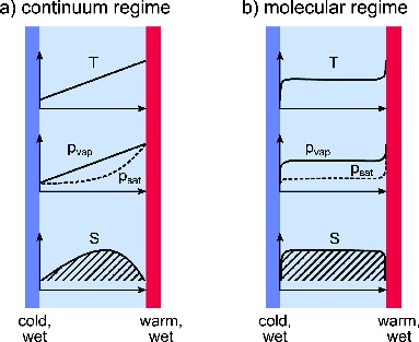
The diffusion chamber was introduced by Langsdorf (Citation1939) as a device to create a stationary and well-controlled volume of supersaturated vapor. In its most simple form, it comprises two large parallel plates held at a close distance from each other. The opposing surfaces are coated with the condensed phase of the species of interest, and are kept at disparate temperatures. If the transport of heat and vapor from the warm to the cold plate is governed by diffusion, an approximately linear gradient of both parameters is established in the space between the plates (Brown and Schowengerdt Citation1979).
A schematic representation of this situation is given in , which illustrates that a highly nonlinear dependence of vapor pressure on temperature gives rise to a central zone of supersaturation. The diffusion chamber principle is not limited to the coplanar geometry depicted above and other geometrical arrangements, e.g., concentric cylinders have been employed (Severynse Citation1964; Saxena and Carstens Citation1971; Rogers Citation1988). It may be extended to arbitrary geometries by applying the stationary diffusion equation for temperature and vapor in that geometry. If however the device is operated in the regime of free molecular flow, i.e., if the mean free path in the gas phase is larger than the distance between the plates, this situation changes. Under these conditions, the molecules evaporating from each wall retain their Maxwellian velocity distribution corresponding to the temperature of that wall. The particle temperature and the concentration of vapor molecules at any point in space can be calculated in a straightforward way to be the arithmetic average of the temperatures and saturation concentration of the walls weighted with the solid angle fraction under which each wall is seen by the particle (for details, see the Appendix). In the case of two parallel plates, the respective high temperature and low temperature weighting fractions are constants of ½ and independent of position. This situation is depicted in . As exemplified for the actual geometry of MICE given below, the supersaturation under free molecular flow conditions is generally higher and spatially more extended than in the diffusion-limited case.
FIG. 1. Schematic representation of a supersaturation chambers: (a) diffusion cloud chamber, (b) free molecular flow cloud chamber. The slightly rounded edges of all curves in (b) reflect the fact that the molecular flow assumption breaks down for infinitely sized plates.
DESIGN OF THE MOLECULAR FLOW ICE CELL (MICE)
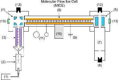
The MICE instrument is part of the TRAPS apparatus (Meinen et al. Citation2010a,Citationb), which is sketched in and which is only briefly recalled here. It comprises a high intensity source for singly charged small nanoparticles (1), an aerodynamic lens (2) optimized to focus these nanoparticles into an vacuum- apparatus, an ion guide (3) to moderate and precool the particles, two quadrupole deflectors (4) and (5) to introduce and extract the particles from a temperature-variable linear nanoparticle trap (6), and a time-of-flight (TOF) nanoparticle mass spectrometer (7) to analyze the mass of the particles after extraction.
FIG. 2. Schematic setup of the TRAPS apparatus, including MICE. The labeled parts are: (1) nanoparticle source, (2) aerodynamic lens, (3) octupole ion guide, (4) quadrupole deflector, (5) quadrupole deflector rotated by 90° into plane, (6) MICE, (7) wide range time-of-flight mass spectrometer, (8) Daly-type nanoparticle detector, (9) mass flow-regulated gas inlet, (10) cryo stage, (11) residual gas analyzer and pressure gauge, (12) Faraday cup detector, and (13) high reflectivity optical cavity mirror.
The MICE replaces the linear nanoparticle trap (6). It combines an ion trap with a supersaturation chamber, and its geometry is depicted in . The ion trap (r0 = 7 mm) is made of four parallel gold-plated copper rods (length = 480 mm) with semi-circular cross section (d = 16 mm) in a quadratic arrangement, to which the rf-AC potentials are applied. The potential on these rods creates the trapping fields for particle containment. The rods are mounted inside a copper tube using SHAPAL™ (Tokuyama Corp., Tokyo, Japan) ceramic spacers as electrical insulators providing a high thermal conductivity. This assembly is mounted on a helium-closed cycle cryostat (DE-104B-Turbo, Advanced Research Systems Inc.) and serves as a cold wall in our setup. Under typical static operation conditions, we measured the maximum temperature difference between the outer tube and the quadrupole rods (kept at ground potential) to be below 0.1 K.
FIG. 3. Design of MICE. Radial cross section shown in panel (a) and perspective view on reduced scale with cooling tube omitted in panel (b). The labeled parts are: (1) cooling tube, (2) quadrupole ion trap electrodes, (3) SHAPAL spacers, (4) heated electrode on ground potential, (5) PEEK spacers, (6) heating foils, (7) temperature sensor cavities, and (8) retractable condensable vapor applicator tube.
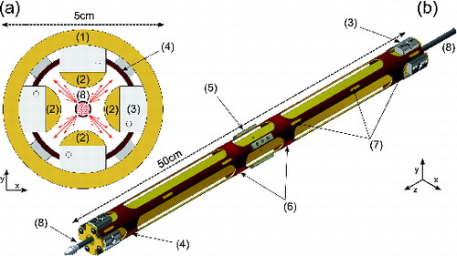
Radially located between the cooling tube and the quadrupole rods, is an additional tube made of gold-plated copper, which has openings at the angular positions of the quadrupole electrodes but covers the space between them. It is kept at electric ground potential and acts as a warm wall in our setup. Therefore, it is mounted to the outer tube using PEEK™ (Victrex plc., Lancashire, UK) spacers, which feature a very low thermal conductivity. The warm wall is heated using two heating foils located in an optimized position to minimize temperature gradients along the element. Six calibrated PT100 temperature sensors are placed in small cavities along its longitudinal coordinate. One of the sensors is used for temperature regulation, while the remaining five are used for temperature monitoring.
In order to produce supersaturation, the warm and cold walls have to be covered with a layer of a condensable substance while being held at a low temperature. To deposit this layer prior to an experiment, a hollow stainless steel tube extending over the full length of MICE may be inserted via a feedthrough on the central axis ( (8)). The tube is closed on the far end and is connected to the vapor of the condensate at the other end. It carries four rows of laser-drilled holes along its linear axis. Each row comprises 100 holes each with a diameter of 100 μm, and 5-mm spacing between each hole such that the length of the particle trap is covered. The rows are located at 90° angles in the direction of the warm wall in order to direct vapor exiting through the holes, preferentially to the inner surface of the warm wall, as indicated by the arrows in . At a typical vapor pressure of several hectopascals (hPa) inside the tube, the deposition is conducted for about 10 min to yield a typical layer thickness of 20 to 30 μm.
For the chosen geometry, the temperature and vapor concentration profiles cannot be calculated analytically as compared with the idealized geometry discussed in the previous section. The diffusion equation has been solved numerically and the geometrical warm and cold wall weighting fractions have been calculated as a function of position.
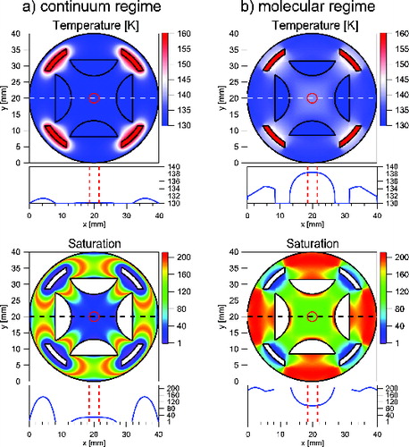
In we compare the calculated temperature distribution and supersaturation profile for both diffusive () and free molecular flow () using the established parameterization for the saturation vapor pressure over Ice Ih from Murphy and Koop (Citation2005). The lower panels show a central cross section of temperature and saturation profiles along the horizontal dashed line. As noted above, supersaturation under free molecular flow condition reaches higher values and extends over a larger volume than in the diffusive case. In both cases, the profiles are sufficiently flat to ensure homogeneous conditions for the particles that are stored in the particle trap. The radial particle density distribution in a gas-filled linear quadrupole trap has been measured and calculated previously (Majima et al. Citation2012). From their results one can estimate that under typical operational conditions (Vrf = 800 V, Ω = 2π × 50 kHz, m = 1.2 × 10⁵ u, q = +1e) and a well-filled particle trap (N = 108) the ion cloud is radially confined to a radius of 1 mm around the central axis of the ion trap (indicated by a vertical dashed line in ).
FIG. 4. Calculated radial temperature and saturation profiles of MICE in the (a) viscous and (b) molecular regime for selected temperatures of 130 K (cold electrodes) and 160 K (warm electrodes). Horizontal cross sections are shown right below each plot. Vertical dashed lines and the central dashed circles indicate ion cloud extent during typical operation conditions.
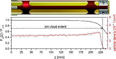
Close to the ends of the particle trap, the temperature and saturation profiles are no longer constant, as the ion lenses at the entrance and exit of MICE are part of the cold wall temperature. This does not introduce much inhomogeneity, as illustrated by the warm surface weighting function Fw (see the Appendix), which is given along the central axis in . A zone of reduced Fw, and the reduced supersaturation, extends to about 10% of the total length of the trap into each end of the trap. Fortunately, the end electrodes repel the particles so that this zone is also a zone of reduced particle density (, dashed line).
FIG. 5. Warm surface weighting function Fw (solid line, left scale) and particle density from a SIMION simulation (circles, right axis) along the axis of MICE. For symmetry reasons, only one-half of the device is shown.
EXPERIMENTS
The setup presented above has been characterized in a series of experiments using nanoparticles of various metal oxides and both water and CO2 vapors. All experiments were performed at low temperatures of between 80 K and 150 K where the corresponding vapor pressure is low enough to obtain a stable operation of the trap and the deposit of solid phase on the warm walls is depleted at a rate low enough to be compatible with several hours of operation of MICE. The trap is operated at a background of helium gas of about 0.2 Pa. Under these conditions, helium atoms are much more abundant than vapor molecules. This ensures that the temperature of nanoparticles and wall surfaces is not influenced by the latent heat associated with evaporation and condensation processes. At the same time, the density of helium atoms is still low enough to operate the trap in the regime of free molecular flow (see discussion of ), which allows for a higher and more homogeneous supersaturation to be applied.
FIG. 6. Total number of particles stored in the ion trap as a function of the filling time for m = 1.8 × 10⁵ u SiO2 particles with Vrf = 950 V and f = 50 kHz. The trap capacity for SiO2 particles of the selected mass is about 8 × 10⁸ particles, which correspond to an average particle density within the ion cloud of about 4.5 × 10⁸ 1/cm3.
FIG. 7. Trapping efficiency of MICE. Shown is the number of particles stored in the ion trap normalized to the average as a function of trapping time for two selected particle masses.
FIG. 8. Time-of-flight spectra for silicon oxide particles at water vapor growth conditions in MICE for five different trapping periods. Raw data in gray overlayed with smooth curves using the third-order Savitzy–Golay filter.
FIG. 9. Deposition growth of water vapor on silicon oxide particles measured at three different particle temperatures and saturations at a constant water vapor concentration. Solid lines are fits using a linear combination of exponential decay and second-order polynomial.
FIG. 10. Water vapor deposition rate on silicon oxide particles as a function of helium background gas pressure (lower scale) and corresponding Knudsen number (upper scale).
A typical MICE–TRAPS experiment starts by cooling MICE to a temperature well below the lowest temperature to be applied to the cold wall. Under these conditions, the condensed phase of the material under investigation is frozen on the wall electrodes as detailed above. The thickness of the applied layers has to yield a reasonable reservoir of material on the warm wall surface for an extended period of operation of the supersaturation cell, and at the same time should not significantly disturb the electrical characteristics of the particle trap. It was found that a layer thickness of about 100 μm is acceptable. After applying the vapor, the particle trap is warmed to the temperature of the cold wall, and after complete thermalization, the warm wall is heated further to its preset operation temperature.
Small nanoparticles of 2–4-nm radius are produced in a microwave discharge particle source by mixing a volatile metal–organic precursor gas with oxygen and a superabundance of helium, and exposing the mixture to a microwave discharge (Chou and Phillips Citation1992; Vollath et al. Citation1997; Janzen et al. Citation2002; Szabó Citation2013). The resulting nanoparticles are introduced into the vacuum system via an aerodynamic lens optimized for particles of that size (Meinen et al. Citation2010a,Citationb). These are moderated in the first helium-filled octupole ion guide before singly charged particles of one polarity are directed into MICE by means of an electrostatic quadrupole deflector operating at a deflection voltage between 50 V and 250 V. In , we give the total number of particles in MICE as a function of duration of filling. The maximum capacity of the trap of about 8 × 10⁸ particles is approached after filling it for about 60 s. For the experiments described herein, the trap was operated at a total charge of about·107 particles, which relates to an ion cloud radius of less than 0.5 mm. This is reached after a short filling time of 1–2 s. Then the electrostatic entrance lens of MICE is closed and no more particles are admitted to the trap. Without any condensable vapor present, the particles may be stored under these conditions for more than 1000 s with negligible losses. This is shown in where the amount of particles in the trap is given as a function of storage time. A slight variation in stored particle amount is due to fluctuations in the particle number density of the nanoparticle source during independent experiments.
During a typical experiment, bunches of nanoparticles are extracted from MICE at subsequently longer residence time in the trap via the exit lens and are fed into a TOF mass spectrometer. Each bunch consists of ∼105 particles so that the trap is not substantially depleted by the extraction. The TOF mass spectrometer is a home-build device which employs a Daly-type detector for an efficient detection of large particles (Daly Citation1960). Its acceleration region is made of a modified quadrupole deflector unit. This allows interfacing the particle beam to other detectors and further experiments. This flexibility comes at the cost of a reduced mass resolution of about m/Δm = 100, which is sufficient for the application described herein. Details of this setup will be given in a subsequent publication. Any particle mass change with trapping time is quantitatively attributed to condensation processes occurring within MICE, as the flight time in the mass spectrometer is too short for significant particle evaporation.
This principle of measurement is demonstrated in , where raw mass spectra of nanoparticles exposed to (a) low and (b) high concentrations of water vapor are displayed as a function of residence time. It is evident that in both cases, the particles gain mass by the deposition and growth of ice, but the growth rate is much higher at the higher nominal supersaturation.
From such measurements, the mass growth rate of nanoparticles can be determined as a function of experimental parameters. In , we exemplarily present three different types of observed behavior. At low supersaturation (a) we observe an initial rapid growth of particles that quickly levels off. At moderate supersaturation (b), a transition into an unlimited growth regime can be observed, while at higher supersaturation (c) the unlimited growth starts immediately and proceeds faster.
From the asymptotical value of the adsorption traces as shown in we get the equilibrium concentration of molecules on the particle surface assuming a Langmuir-type adsorption model (Langmuir Citation1918) assuming sub-monolayer coverage and spherical adsorbates. We can further analyze surface concentration using an adsorption–desorption equilibrium model (Pruppacher and Klett Citation2004, chap. 9.1.3). As the vapor concentration in the gas phase and the temperature are well known, the only remaining free parameter is the surface adsorption energy of vapor molecules, which can thus be deduced. In the unlimited growth regime () the sticking coefficient can be derived by comparing the measured with the theoretical mass growth rate in the gas kinetic regime (Brown et al. Citation1996; Davis Citation2006).
From the growth curves at intermediate supersaturation as depicted in Figure 9b, the nucleation rate can be obtained. The saturation set in the measurement of curves (a) and (b) in Figure 9 can serve as lower and upper limit in the estimation of the critical saturation for nucleation. By applying the classical surface diffusion nucleation theory (Keesee Citation1989; Pruppacher and Klett Citation2004; Määttänen et al. Citation2005) using the above-determined parameters of desorption energy and nucleation rate, the effective contact angle between nanoparticle surface and the solid phase of the vapor can be deduced. Details of this analysis for different gases and nanoparticle materials will be given in forthcoming publications.
In , we plot the mass growth rate of water ice on SiO2 particles as a function of helium background gas pressure and associated Knudsen number (Kn, upper axis) under otherwise constant conditions. The curve clearly features a plateau region at lower pressure. At higher pressure, we observe a pronounced decrease in growth rate, which we attribute to the onset of the transition flow regime, which is accompanied by reduced supersaturation at trap center. It is reassuring that an area of operation can be found that allows for stable trapping of particles but is not influenced by the complications of transition flow regime. For our experiments, we always limit the background gas pressure to remain in the molecular flow regime.
DISCUSSION
So far, we have studied the formation of solid water ice and CO2 ice on mineral nanoparticles made of iron oxide, silicon oxide, and iron-silicates, which are considered as proxy of meteoric dust nanoparticles found in upper planetary atmospheres. The size-, material-, and supersaturation-dependent nucleation and growth rates measured will be the focus of subsequent publications. Here we summarize our findings on the general applicability and limitations of this new device.
The MICE proved to be a powerful tool in observing the adsorption–nucleation and growth of condensable vapors in a pressure regime compatible with molecular flow. By analyzing surface adsorption measurements, we were able to derive effective nanoparticle surface areas and surface desorption energies. In the future experiments, it might be possible to study the effect of surface coatings and functional groups on these properties.
We observe that the critical vapor supersaturation needed for the nucleation of the new phase depends strongly on the type of vapor (so far, H2O and CO2 have been investigated). Comparing with the classical heterogeneous nucleation theory, the effective contact angle between nanoparticle surface and the solid phase of the vapor can be determined. By analyzing the mass growth rate of particles at high supersaturation, we can determine temperature-dependent sticking coefficients for various vapors.
As detailed above, the proper functioning of the device is bound to some constraints. The pressure of the background gas needed for trapping and thermalization (helium in our case) has to be much higher than the partial pressure of the vapors involved and should lie between 0.01 Pa and 0.4 Pa. The lower limit ensures sufficient friction to trap and store the particles, while the upper limit is given by the molecular flow constraint (). Both limits are slightly geometry-dependent and background gas-dependent. At the same time, the concentration of vapor molecules has to be much lower than the concentration of the background gas atoms to ensure thermal equilibrium, especially under conditions of depositional growth. At 170 K warm wall temperature and a background pressure of 0.2 Pa, the concentration of water molecules is below 1% of the concentration of helium atoms. Under these conditions, the latent heat of condensation warms the particles by at most 0.15 K. The rate of evaporation and the thickness of the condensed phase on the warm walls limit the operation over longer periods of MICE at higher temperatures. At 170 K, the rate of evaporation of water ice Ih in vacuo is about 4 μm/h. With an initial deposit thickness of 10 μm, this results in acceptable maximum experiment duration of 5 h. At warmer temperatures, the deposit will be depleted much faster. The respective upper temperature limit for CO2 experiments is about 90 K. Experiments are limited toward lower temperatures by the availability of vapor. Under growth conditions, the amount of deposited vapor within the experimental duration has to exceed the mass resolution of the TOF mass spectrometer. These constraints define particle temperature and saturation range, which can be investigated with the device. The accessible range is given in exemplarily for water vapor and CO2.
FIG. 11. Operation regimes of MICE for water vapor and CO2. Isothermals of cold wall (solid lines) and warm wall temperature (dashed lines) with numbers in degree Kelvin.
So far, we have successfully applied the device to study the nucleation of water and CO2 vapors on nanometer-sized proxy-particles for meteoric smoke found in upper planetary atmospheres. In the future, we will use MICE to extend these studies by performing an elemental analysis of the processed nanoparticles using complete laser evaporation (Wang et al. Citation2006; Zordan et al. Citation2010) and by studying the optical properties of growing nanoparticle systems by cavity-enhanced absorption spectroscopy (Meinen et al. Citation2012). We envision, however, that similar devices can be used successfully in other fields of science ranging from catalysis to food- and drug-science.
FUNDING
We gratefully acknowledge the financial support by the German Research Foundation (DFG) under grant number LE 834/4-1, and by the German Federal Ministry of Education and Research (BMBF) under grant number 05K13VH3.
REFERENCES
- Antonsson, E., Bresch, H., Lewinski, R., Wassermann, B., Leisner, T., Graf, C., Langer, B., and Rühl, E. (2013). Free Nanoparticles Studied by Soft X-rays. Chem. Phys. Lett., 559:1–11.
- Bluhm, H., Andersson, K., Araki, T., Benzerara, K., Brown, G. E., Dynes, J. J., Ghosal, S., Gilles, M. K., et al. (2006). Soft X-ray Microscopy and Spectroscopy at the Molecular Environmental Science Beamline at the Advanced Light Source. J. Electron Spectrosc. Relat. Phenom., 150(2–3):86–104.
- Brown, D. E., George, S. M., Huang, C., Wong, E. K. L., Rider, K. B., Smith, R. S., and Kay, B. D. (1996). H2O Condensation Coefficient and Refractive Index for Vapor-Deposited ice from Molecular Beam and Optical Interference Measurements. J. Phys. Chem., 100(12):4988–4995.
- Brown, J. T., Jr., and Schowengerdt, F. D. (1979). Analysis of a Continuous Flow Parallel Plate Thermal Diffusion Cloud Chamber. J. Aerosol Sci., 10(3):339–348.
- Chou, C. H., and Phillips, J. (1992). Plasma Production of Metallic Nanoparticles. J. Mat. Res., 7(8):2107–2113.
- Daly, N. R. (1960). Scintillation Type Mass Spectrometer Ion Detector. Rev. Sci. Instrum., 31(3):264–267.
- Davis, E. J. (2006). A History and State-of-the-Art of Accommodation Coefficients. Atmos. Res., 82(3–4):561–578.
- Gumbel, J., and Megner, L. (2009). Charged Meteoric Smoke as Ice Nuclei in the Mesosphere: Part 1-A Review of Basic Concepts. J. Atmos. Solar Terrestrial Phys., 71(12)1225–1235.
- Janzen, C., Kleinwechter, H., Knipping, J., Wiggers, H., and Roth, P. (2002). Size Analysis in Low-Pressure Nanoparticle Reactors: Comparison of Particle Mass Spectrometry with in Situ Probing Transmission Electron Microscopy. J. Aerosol Sci., 33(6):833–841.
- Keesee, R. G. (1989). Nucleation and Particle Formation in the Upper-Atmosphere. J. Geophys. Res. Atmos., 94(D12):14683–14692.
- Langmuir, I. (1918). The Adsorption of Gases on Plane Surfaces of Glass, Mica and Platinum. J. Am. Chem. Soc., 40(9):1361–1403.
- Langsdorf, A. (1939). A Continuously Sensitive Diffusion Cloud Chamber. Rev. Sci. Instrum., 10(3):91–103.
- Liu, J. Y. (2005). Scanning Transmission Electron Microscopy and its Application to the Study of Nanoparticles and Nanoparticle Systems. J. Electron Micros., 54(3):251–278.
- Määttänen, A., Vehkamäki, H., Lauri, A., Merikallio, S., Kauhanen, J., Savijärvi, H., and Kulmala, M. (2005). Nucleation Studies in the Martian Atmosphere. J. Geophys. Res. Planets 110(E2).
- Majima, T., Santambrogio, G., Bartels, C., Terasaki, A., Kondow, T., Meinen, J. and Leisner, T. (2012). Spatial Distribution of Ions in a Linear Octopole Radio-Frequency Ion Trap in the Space-Charge Limit. Phys. Rev. A 85(5):085107.
- Meinen, J., Eritt, M., Bartels, C., Terasaki, A., Kondow, T., Meinen, J., and Leisner, T. (2012). Optical Properties of Free Sub-10-nm Diameter Fe2O3 Nanoparticles Studied by Broad-band Cavity Enhanced Absorption Spectroscopy (BB-CEAS). Appl. Phys. B, 108(3):641–647.
- Meinen, J., Khasminskaya, S., Habig, J. C., and Leisner, T. (2010a). Core Level Photoionization on Free Sub-10-nm Nanoparticles Using Synchrotron Radiation. Rev. Sci. Instrum., 81(8):053141.
- Meinen, J., Khasminskaya, S., Eritt, M., Leisner, T., Antonsson, E., Langer, B., and Ruehl, E. (2010b). The TRAPS Apparatus: Enhancing Target Density of Nanoparticle Beams in Vacuum for X-ray and Optical Spectroscopy. Aerosol Sci. Technol., 44(4):316–328.
- Murphy, D. M. (2007). The Design of Single Particle Laser Mass Spectrometers. Mass Spectrom. Rev., 26(2):150–165.
- Murphy, D. M., and Koop, T. (2005). Review of the Vapour Pressures of Ice and Supercooled Water for Atmospheric Applications. Quart. J. Royal Meteor. Soc., 131(608):1539–1565.
- Mysak, E. R., Starr, D. E., Wilson, K. R., and Bluhm, H. (2010). Note: A Combined Aerodynamic Lens/Ambient Pressure X-ray Photoelectron Spectroscopy Experiment for the On-stream Investigation of Aerosol Surfaces. Rev. Sci. Instrum., 81(1):016106.
- Nishiyama, H., Koizumi, M., Ogawa, K., Kitamura, S., Konyuba, Y., Watanabe, Y., Ohbayashi, N., Fukuda, M., et al. (2014). Atmospheric Scanning Electron Microscope System with an Open Sample Chamber: Configuration and Applications. Ultramicroscopy 147:86–97.
- Pruppacher, H. R., and Klett, J. D. (2004). Microphysics of Clouds and Precipitation. Kluwer, Dordrecht, Netherlands.
- Rapp, M., and Thomas, G. E. (2006). Modeling the Microphysics of Mesospheric Ice Particles: Assessment of Current Capabilities and Basic Sensitivities. J. Atmos. Solar Terrestrial Phys., 68(7):715–744.
- Rogers, D. C. (1988). Development of a Continuous Flow Thermal Gradient Diffusion Chamber for Ice Nucleation Studies. Atmos. Res., 22(2):149–181.
- Salmeron, M., and Schlögl, R. (2008). Ambient Pressure Photoelectron Spectroscopy: A New Tool for Surface Science and Nanotechnology. Surf. Sci. Rep., 63(4):169–199.
- Saxena, V. K., and Carstens, J. C. (1971). On the Operation of Cylindrical Thermal Diffusion Cloud Chambers. J. de Recherches Atmospheriques 5:11–23.
- Severynse, G. T. (1964). A Portable Cloud Nuclei Counter. J. de Recherches Atmospheriques 1:11–16.
- Szabó, D. V. (2013). Microwave Plasma Synthesis of Nanoparticles. Microwaves in Nanoparticle Synthesis: Fundamentals and Applications, S. Horikoshi and N. Serpone (Eds.), Wiley-VCH, Weinheim, pp. 271–310.
- van der Veen, R. M., Kwon, O.-H., Tissot, A., Hauser, A., and Zewail, A. H. (2013). Single-Nanoparticle Phase Transitions Visualized by Four-Dimensional Electron Microscopy. Nat Chem., 5(5):395–402.
- Vollath, D., Szabo, D. V., Taylor, R. D., and Willis, J. O. (1997). Synthesis and Magnetic Properties of Nanostructured Maghemite. J. Mat. Res., 12(8):2175–2182.
- Wang, S., and M. V. Johnston (2006). Airborne Nanoparticle Characterization with a Digital Ion Trap–Reflectron Time of Flight Mass Spectrometer. Int. J. Mass Spectrom., 258(1–3):50–57.
- Wang, S., Zordan, C. A., and Johnston, M. V. (2006). Chemical Characterization of Individual, Airborne Sub-10-nm Particles and Molecules. Anal. Chem., 78(6):1750–1754.
- Wilson, K. R., Shengli, Z., Jinian, S., Rühl, E., Leone, S. R., Schatz, G. C., and Ahmed, M. (2007). Size-Dependent Angular Distributions of Low-Energy Photoelectrons Emitted from NaCI Nanoparticles. Nano Lett., 7(7):2014–2019.
- Wu, C.-K., Yin, M., O'Brien, S., and Koberstein, J. T. (2006). Quantitative Analysis of Copper Oxide Nanoparticle Composition and Structure by X-ray Photoelectron Spectroscopy. Chem. Mat., 18(25):6054–6058.
- Zordan, C. A., Pennington, M. R., and Johnston, M. V. (2010). Elemental Composition of Nanoparticles with the Nano Aerosol Mass Spectrometer. Anal. Chem., 82(19):8034–8038.
APPENDIX: THE CALCULATION OF SUPERSATURATION IN MICE
We discuss the equilibrium temperature and saturation seen by a particle completely surrounded by several (n) walls kept at temperatures Ti (1 ≤ i ≤ n) and covered with the condensed phase of volatile substance. The space within the walls is filled with atoms of an inert background gas, which are assumed to be much more abundant than the molecules of vapor, but still rarefied enough to ensure free molecular flow. The notion of atoms of the background gas and the molecules of vapor is ambiguous and adopted here only for brevity; in principle, both gases may be either atomic or molecular. Neglecting radiative and latent heat transfer, the particle temperature at a location is governed by the exchange of thermal energy with the atoms originating from the walls.
Once a stationary state has been assumed, the flux of atoms from each wall is identical. With each collision between an atom and a particle, an energy of Ui = αcvΔTi is exchanged. Here α is the energy accommodation coefficient, cv is the heat capacity of the atom, and ΔTi is the difference between particle temperature and the temperature of the wall that emitted the atom. Solving for a stationary particle energy budget in thermal equilibrium under the assumption of a negligible variation of α with temperature (Semyonov et al. 1984), the position-dependent particle temperature is calculated to be[A1] where the weighting function Fi is the relative solid angle, under which the wall (i) is visible from the position
.
In the molecular regime, the saturation S at the particle location is given by the ratio of the flux of condensable vapor molecules at the particle location relative to the flux of molecules the particle would experience when being in equilibrium with the condensed phase at the particle temperature,[A2]
The equilibrium flux over the condensed phase is[A3] where psat is the saturation vapor pressure and
is the mean thermal velocity of vapor phase molecules of molecular mass m at the particle temperature Tp. The total flux of condensable vapor molecules toward the particle surface is given by the sum of the fluxes from the walls weighted with their respective weighting function,
[A4]
Equations Equation(A1)[A1] and Equation(A4)
[A4] show that in the molecular regime temperature and saturation, conditions are determined by the solid angle weighting functions. In contrast, in the continuum case, the conditions are governed by the temperature and concentration gradients.
In this article, we deal with two walls only, i.e., the warm wall at temperature Tw with weighting function Fw and the cold wall at temperature Tc and weighting function (1–Fw).