
ABSTRACT
The problem of large pressure-differential-driven laminar convective–diffusive ultrafine aerosol flow through bent microtubes is of interest in several contemporary research areas including; release of contents from pressurized containment vessels, aerosol sampling equipment, advanced scientific instruments, gas-phase microheat exchangers, and microfluidic devices. In each of these areas, the predominant problem is the determination of the fraction of particles entering the microtube that is deposited within the tube and the fraction that is transmitted through. Due to the extensive parameter restrictions of this class of problems, a Lagrangian particle tracking method making use of the coupling of the analytical stream line solutions of Dean for convective motion and a sampling of a Gaussian distribution for diffusive motion is a useful tool in problem characterization. This method is a direct analog to the Monte Carlo N-Particle method of particle transport extensively used in nuclear physics and engineering. In this work, 10-nm-diameter particles with a density of 1 g/cm3 are tracked within microtubes with toroidal bends with pressure differentials ranging between 0.2175 and 0.87 atmospheres. The tubes have radii of 25 microns or 50 microns and the radius of curvature is either 1 m or 0.3183 cm. The carrier gas is helium, and temperatures of 298 K and 558 K are considered. Numerical convergence is considered as a function of time step size and of the number of particles per simulation. Particle transmission rates and deposition patterns within the bent microtubes are calculated.
Copyright © 2016 American Association for Aerosol Research
EDITOR:
Introduction
Although Dean provided analytical treatments of fully-developed laminar flow in bent tubes the better part of a century ago (Dean Citation1927, Citation1928), and Gormley and Kennedy provided an analytical solution for laminar convective–diffusive flow in straight tubes over a half-century ago (Gormley and Kennedy Citation1949), the problem of fluid flow with and without suspended particles in bent tubes of various flow conditions (laminar and turbulent) has remained a constant topic of academic investigation (Taylor Citation1929; Ito Citation1959; Van Dyke Citation1978; Berger et al. Citation1983; Tsai and Pui Citation1990; Guan and Martonen Citation1997; Wang et al. Citation2002; Quek et al Citation2005; Breuer et al. Citation2006; Yook and Pui Citation2006; Pilou et al. Citation2011; Zhang et al. Citation2012; Sun and Lu Citation2013; Lin et al. Citation2015; Vasquez et al. Citation2015). Each study involving such systems considers various mathematical treatments for the system of interest with the main division between modeling techniques being whether the treatment is Eulerian or Lagrangian (Zhang and Chen Citation2007).
The work presented in this study grew out of a desire to determine the behavior of ultrafine radioactive particle flows out of used nuclear fuel dry storage containers in the event of the formation over time of microscale through-wall pinhole breaches (Casella Citation2007a; Casella et al. Citation2007b, Citation2014). This concern regarding radioactive particle transport through small failure pathways has been shared by other researchers considering similar systems (Williams Citation1994; Morton and Mitchell Citation1995; Williams Citation1996). Dry storage containers for nuclear fuel have helium backfill gas due to its inert nature and excellent heat transport properties for gaseous systems. This backfill can range in initial pressure from 1 to 5 atmospheres. Decay heat from the used fuel will increase the backfill gas temperature after the container is sealed so that in any case, a significant pressure differential will exist across any breach that forms in the container wall. Due to the same engineering considerations for heat and mass transport, similarly high-pressure-driven helium flows are likely to be encountered in gas-phase microheat exchangers. Such devices would likely involve bent tubes due to the desire to minimize the size of the device and to make use of the enhanced thermal transport achieved with the secondary flows that develop in flow in bent tubes. The deposition of particulates within these devices is of concern as it will lead to fouling. The transport and deposition of particles within microscale aerosol collectors is also a current topic of concern (Novosselov et al. Citation2014), and these systems will likely become more concerned with ultrafine particles and smaller tubes as technology continues to progress toward their miniaturization. Likewise, as instruments for scientific investigation such as mass spectrometers continue to advance, ultrafine particle transport in bent microtubes will be of greater interest. Additionally, as the science and engineering of microfluidic devices progresses, particle deposition leading to fouling and blocking will become an issue of growing concern (Sharp and Adrian Citation2005; Tavakoli et al. Citation2011; Marshall and Renjitham Citation2015).
The model developed and presented in this article tracks 10-nm-diameter particles through bent tubes with radii of 25 or 50 µm. Many parameters of consideration can be neglected at these scales. This model has generated results for particle transmission and deposition in these systems and can be used as a basis of comparison for future models and studies.
Theory: Characterization of the carrier gas
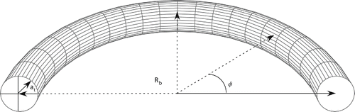
The key parameters defining toroidal flow system geometries are displayed in ; Rb is the radius of curvature, at is the tube radius, and is the curvature angle. Additionally, the central curve around which the toroid is constructed is defined as
[1] and if the central curve originates at the point
= 0, then the distance from the central curve origin to any other point on the central curve is
[2]
Figure 1. Important parameters defining toroidal flow system geometries.
The description of fluid flow through the toroid was developed by considering perturbations from straight tubes (Rb → ∞). In the case of a straight tube, the axial flow streamlines are defined by the Poiseuille equation (Bird et al. Citation2007)[3] where w is the axial velocity, P0 is the pressure at the tube inlet, PL is the pressure at the tube exit, µ is the viscosity, L is the tube length, and r is the radial location within the tube. The streamline definition of EquationEquation (3)
[3] is only applicable when the flow is laminar as defined by the Reynolds number (Bird et al. Citation2007)
[4] where ρ is the gas density and W0 is the maximum axial velocity (EquationEquation (3)
[3] evaluated for r = 0). As the tube is bent, the Reynolds Number is replaced by the Dean number (Dean Citation1927, Citation1928)
[5] where W0 is the maximum velocity in a straight pipe of the same radius and with the same pressure gradient as the bent tube being characterized, ν is the kinematic viscosity
[6] and
[7]
EquationEquation (5)[5] is the definition of the Dean number as it was originally defined by Dean, yet many other variations have been proposed (Van Dyke Citation1978; Berger et al. Citation1983). It seems that the contemporary consensus has become to write the Dean number as (Tsai and Pui Citation1990; Guan and Martonen Citation1997; Wang et al. Citation2002; Yook and Pui Citation2006)
[8]
However, as this article will utilize the original work of Dean, EquationEquation (5)[5] is used. There are several claims as to the critical value of K for which the flow becomes turbulent and reported values range as high as K ≈ 1.6 × 10⁶ (Berger et al. Citation1983; Taylor Citation1929). Others choose to deconstruct the Dean number and characterize the laminar/turbulent flow divide as something like: for the range 15 < R0 < 860, turbulent flow begins according to the Reynolds number (Ito Citation1959)
[9]
Dean noted that for laminar flow in bent tubes for which R0 is large, EquationEquation (3)[3] can be rewritten as the first-order approximation to the infinite expansion
[10] where
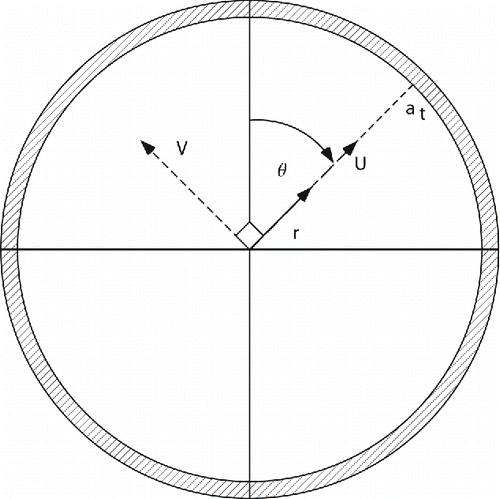
[11] and θ is defined in . also introduces the parameters U and V, which are the two perpendicular velocity components of the secondary flow that develops from flow through the bent tube. Dean noted that for the same conditions that lead to the development of EquationEquation (10)
[10] , the components of the secondary flow velocity could be written as the first-order approximations to the infinite expansions
Figure 2. Definition of secondary flow velocity parameters.
Characterization of the particle motion
The particles considered in this study are 10 nm in diameter and are uncharged. Thus, gravitational settling and electromagnetic forces can be neglected. Additionally, they are dilute in concentration and particle–particle collisions are neglected. As particle motion is only influenced by the convective motion of the carrier gas and Brownian motion, the phenomenon being studied is identified as convective–diffusive particle transport (Williams and Loyalka Citation1991).
The behavior of a suspended particle relative to the carrier gas streamline in curvilinear motion is a common problem in evaluating collection efficiency in impactor theory. The deviation of particle motion from the streamline behavior of the carrier gas is assessed with the Stokes number[14] where
is the particle density,
is the particle diameter, and
is the Cunningham correction factor (Hinds Citation1999)
[15] and λ is the mean free path of the gas. If Stk >> 1 for flow in a curvilinear system, suspended particles will continue motion in a straight line in spite of the curved streamlines of the carrier gas. If Stk << 1, particles can be assumed to follow carrier gas streamlines exactly (Hinds Citation1999). For the particles considered in this article, as can be seen in , Stk << 1.
Table 1. Model parameter space.
While the convective motion of particles in the current study is assumed to follow the convective streamlines of the carrier gas as described in the previous section, the particles will still exhibit a diffusive behavior consistent with Brownian motion (Einstein Citation1956). This motion in one-dimension can be modeled by sampling from a Gaussian distribution over a time step [16] where z is the particle position at time t, z0 is the particle position at time t0,
is the particle density distribution, and
is the slip-corrected Einstein diffusion coefficient (Williams and Loyalka Citation1991) defined as
[17] where k is Boltzmann's constant.
Thus, the Monte Carlo process is simply a marching of the particle position forward in time according to the convective and diffusive motion. For each time step, the particle is advanced in space due to convective motion in the axial direction as described by EquationEquation (10)[10] and in the radial (cross-sectional) direction according to Equations Equation(12)
[12] and Equation(13)
[13] . Additionally, for each time step, displacement due to diffusive motion is determined by independent random samplings from EquationEquation (16)
[16] for movement in the x and y directions within the tube cross-section. Diffusion in the direction of axial flow is neglected as justified by the Péclet number as discussed later. To account for the geometrical distortion caused by the bent tube, the particle motion in the axial direction is tracked as a function of
and the motion in the radial direction is tracked as a function of
and θ. Each step forward in time can be succinctly described by the set of equations
[18]
[19]
[20]
[21]
[22] where the subscript m represents the time step number and subscripts x and y indicate the components of position
lying in the Cartesian cross-sectional coordinates x and y, respectively.
Model
As was stated earlier, in order for Equations Equation(10)[10] –Equation(13)
[13] to be theoretically applicable to flow in a tube, the conditions must be consistent with fully developed laminar flow, so the Reynolds and Dean numbers must be low. These are both held low for micro-tubes due to the presence of the tube radius in the numerator of each number. The tube radius cannot be too small however, as continuum flow transitions to slip flow when the Knudsen number rises above 0.01, and an axial velocity of zero at the tube wall is a boundary condition for Dean's derivations (Karniadakis et al. Citation2005). Additionally, the value of R0 must be much greater than 1 (Berger et al. Citation1983). Also, the particle size must be small enough so that the particle behavior can be expected to closely match that described in the previous section.
As was discussed in the introduction, the work presented in this article grew out of previous work by the authors involving pinhole breaches in nuclear fuel canisters (Casella Citation2007a; Casella et al. Citation2007b, Citation2014). In these previous applications, the tube radius was 5–50 microns, the tube length was 1 cm, particle diameters were in the range of 10 to 50 nanometers, the inlet temperature was 558 K, and the inlet and outlet pressures were 1.87 and 1.0 atmospheres, respectively. This set of parameters became the base case for consideration in this study, with the base tube radius to be considered being 25 microns. In order to determine the effects of doubling the tube radius while keeping the axial velocity constant, a second set of parameters was considered that was identical to the first set, but with the tube radius being 50 microns, and the inlet pressure being 1.2175 atmospheres. In order to determine the effect of changing the radius, but keeping the higher inlet pressure constant and allowing axial velocities to grow (pushing the limits of the model), the third set of parameters was considered that was identical to the first set, but with a tube radius of 50 microns. In order to investigate the effect of system temperature, these three parameter sets were studied with a system temperature of 298 K in place of 558 K, leading to a set of six test cases.
Additionally, for each test case, a straight (large radius of curvature) and a bent (small radius of curvature) tube case was considered for a total of 12 test cases. The curvature of tubes considered in this study (EquationEquation (7)[7] ) for the cases described in the previous paragraph varies from 127 to 40,000 in order to consider the full range of applicability prescribed by Dean (Dean Citation1927, Citation1928). In order to achieve this, the tube length is left unchanged at 1 cm, while the value of Rb (EquationEquation (1)
[1] ) is varied from 1 m to 0.003183 m for tubes with a radius of 25 microns (creating a half toroid according to EquationEquation (2)
[2] ), and from 1 m to 0.006366 m for tubes with a radius of 50 microns (creating a quarter toroid according to EquationEquation (2)
[2] ). The extent of this range in the value of Rb can be appreciated by viewing Figures S1 and S2 in the online supplementary information (SI). The system parameters for these 12 cases are listed in . In all cases, the particles are considered to be 10 nm in diameter and have a density of 1 g/cm3. As an additional consideration, the flow is assumed to be incompressible. This condition translates into the flow velocity being less than 30% the speed of sound in the carrier gas at that temperature. The speed of sound in helium at 558 K and 298 K is 1390 and 1016 m/s, respectively. So, the flow velocity for scenarios considered in this study should be less than 417 m/s at 558K and 305 m/s at 298 K. These conditions are met as can be seen by inspection of .
Results and discussion
For large values of Rb, the toroidal tube closely resembles a straight tube, for which the analytical solution for the particle transmission fraction (the fraction of particles entering the tube that pass through the tube without being deposited) during convective–diffusive flow has been shown to be (Gormley and Kennedy Citation1949; Williams and Loyalka Citation1991)[23] where Pe is the Péclet number defined as
(24)
If a straight tube is bent into a toroidal shape in a fashion prescribed by EquationEquation (1)[1] , it is expected that the axial flow streamlines will become distorted according to EquationEquation (10)
[10] and that secondary flows within the plane perpendicular to the axial direction will be generated according to EquationEquation (12)
[12] and EquationEquation (13)
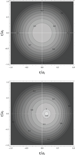
[13] . The secondary flow streamlines are displayed in and the distortion in the axial streamlines generated by the range of Dean numbers considered in this study are displayed in . It is instructive to note that the vector direction of the secondary flow streamlines remains constant for all curved tubes described by the Dean equations; however, the magnitude of these flows is directly dependent on the value of the corresponding Dean number.
Figure 3. Display of the secondary streamlines as defined by EquationEquations (12)[12] and Equation(13)
[13] .
![Figure 3. Display of the secondary streamlines as defined by EquationEquations (12)[12] and Equation(13)[13] .](/cms/asset/258bcf75-785f-4e1f-a940-ac54072f2736/uast_a_1143548_f0003_b.gif)
Figure 4. Axial streamlines (contour lines represent equal axial velocity) for top: a straight tube (K = 0) and for bottom: a bent tube (K = 400). In both cases, W0 has been normalized to 1.
Results
The expected analytical transmission fraction (according to EquationEquation (23)[23] ) for each of the cases involving straight tubes (Rb = 1 m) discussed in the previous section should be very close to the result generated by Monte Carlo N-Particle calculations (Equations Equation(18)
[18] –Equation(22)
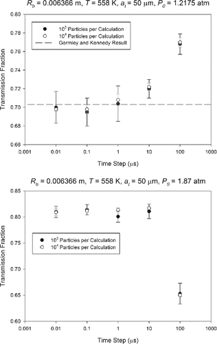
[22] ). If these two results do not match within errors associated with Monte Carlo statistics and the truncation of the infinite series, then it is likely that the Monte Carlo results are not sufficiently converged. In order to investigate this parameter space, a range of number of particles per simulation and time step sizes was considered. Each calculated value is the mean of 10 separate calculations using either 1,000 or 10,000 particles each. The error associated with each of these mean values is taken to be the standard deviation of these same 10 results. The size of the time steps used in the calculations was varied from 100 to 0.01 µs. The comparison of solution results across these considerations: (1) analytical solution value for straight tubes, (2) number of particles per simulation, and (3) size of the time steps can be seen in for the system in which at = 25 µm and P0 = 1.87 atm.
Figure 5. Transmission fractions for at = 25 µm and P0 = 1.87 atmospheres as a function of Rb and T. Each point is the mean of 10 calculations and the error bars represent one standard deviation from the mean of those same 10 calculations.
For the system involving P0 = 1.87 atm and at = 25 µm (), the Monte Carlo result is observed to converge to the Gormley and Kennedy solution for all cases except for the case of T = 298 K and Rb = 0.003183 m. In this case, the transmission fraction predicted by the Gormley and Kennedy expression (EquationEquation (23)[23] ) is 0.723, which is off the scale of the figure. In the other cases in this system, it appears that the errors (standard deviations) decrease with increased particles per simulation (sign of a well-behaved system) and that the solutions converge for calculations in which the time step is 0.1 µs or smaller. The case of Rb = 0.003183 m and T = 558 K appears to potentially be converging to transmission fraction solution that is smaller than that predicted by Gormley and Kennedy, but this is potentially due to statistics. If more than 10 simulations are run for this calculation, or the same 10 simulations repeated, it is likely that the result will be closer to that of Gormley and Kennedy. However, an indication that the result is actually converging to a lower value is that the Monte Carlo result for Rb = 0.003183 m and T = 298 K appears to be converging to a transmission fraction that is significantly lower than that for the case of Rb = 1 m and T = 298 K. Thus, the bent tube case appears to have a lower transmission fraction as compared to the analogous straight tube case. This is an expected result due to the influence of the secondary flows.
The results for the two other systems considered in this study followed similar trends as those presented in for the first system. However, as the model parameters become more extreme (higher pressure differential, lower temperature, higher curvature, higher Dean number), the results deviate more from the analytical solution of Gormley and Kennedy and display slightly different convergence behaviors. Representative results from the second two systems are presented in . Comprehensive results for these two systems are presented in Figures S3 and Figure S4 in the SI. For the representative results from the second system (P0 = 1.2175, at = 50 µm), the results converge to the analytical result in the same way that they did for the first system. For the representative results from the third system (P0 = 1.87, at = 50 µm), the results converge to a transmission fraction significantly lower than that predicted by the Gormley and Kennedy analytical results (0.884). Also, for the larger time steps, the transmission fraction is under-predicted as opposed to the over-prediction for the first two systems. The results of the third system also show deviation from the analytical results for straight and curved tubes at 298 K. This behavior is largely due to the limitations of the assumptions associated with the Dean equations and to the very slow convergence of the Gormley and Kennedy infinite expansion series for cases with nearly total particle transmission.
Figure 6. Selected results from remaining tests sets for illustration.
and are demonstrations in which the Monte Carlo results are representative of tallies which represent the entire particle population. Each particle either passes through the tube of interest, or it is deposited and thus provides a score of 1 or 0. However, more useful results can also be gathered by binning particles in more informative ways as is done in and . These figures provide an axial and a circumferential characterization of the particles deposited in the case of interest. In the axial characterization, the length of the tube (as defined in EquationEquation (2)[2] ) is divided into 10 equal sections (which as Rb is constant, means dividing φ into 10 equal sectors ((π/2)/10 for Rb = 0.006366 or π/10 for Rb = 0.003183)). In the circumferential characterization, the tube cross section is divided into quadrants defined as (with as a reference) quadrant 1 = 0 < θ < π/2, quadrant 2 = −π/2 < θ < 0, quadrant 3 = −π < θ < −π/2, and quadrant 4 = π/2 < θ < π. Again, each of the results is presented as the mean of 10 simulations, each with 10,000 particles, with the error bars representing one standard deviation from the mean. and demonstrate quantitatively the effect of the tube curvature (as a function of Dean number) on the particle deposition patterns. More comprehensive results for the systems considered in this study are presented in Figures S5 through S8 in the SI. For systems with low Dean numbers, the deposition patterns, both axial and circumferential, match those of Gormley and Kennedy fairly well. The discrepancy in the first axial section is again due to the slowly converging nature of the infinite series. As the Dean number of a system increases, the particles are more preferentially deposited in the quadrants associated with the outside of the bend. Also, for larger Dean numbers, greater fractions of particles that enter the tube are deposited. For the systems with the highest Dean number, the axial particle deposition pattern also deviates strongly from the solution of Gormley and Kennedy. In fact, as the Dean number for a system increases, more particles tend to be deposited toward the exit of the tube than the entrance to the tube, which is in stark contrast to the deposition pattern of the Gormley and Kennedy solution. It seems that for these systems, the axial deposition pattern is a function of the ratio of the magnitudes of the secondary and axial flows. This phenomenon can be visually observed in the 3-dimensional particle deposition patterns for each of the systems considered in this study as presented in Figures S9 and S10 in the SI.
Figure 7. Deposition patterns for the system with parameters at = 25 µm, P0 = 1.87 atm, T = 558 K, time step = 0.01 µs.
Figure 8. Deposition patterns for the system with parameters at = 50 µm, P0 = 1.2175 atm, T = 298 K, time step = 0.01 µs.
Discussion
We have explored a methodology for solving the problem of laminar convective–diffusive flow in curved tubes using the streamlines of Dean that is analogous to the problem of laminar convective–diffusive flow in straight tubes using the streamlines of Poiseuille that was solved by Gormley and Kennedy. As the deviation of the axial flow streamlines from the Poiseuille equation and the presence of secondary flows greatly complicate the prospect of an analytical solution, a Monte Carlo computational approach is useful. In order for this approach to be theoretically valid, many system constraints must be met. Real world applications will likely be in the realm of particle leakage through pressurized storage container walls, microheat exchangers, microscale aerosol measurement devices, and advanced scientific instrumentation.
Many studies have raised concerns regarding the validity of many of the assumptions made in the development of the model presented in this article. However, the parametric space in which the model has been developed and applied seems to have alleviated these concerns. The issue of slip boundary conditions being necessary instead of zero-velocity boundary conditions to properly describe gas flow in microchannels has been raised (Tavakoli et al. Citation2011). This is true in many cases, however in the cases presented here, as presented in , the value of the system Knudsen number indicates that the systems are within the continuum regime (Kn < 0.01). Also, the concern has been raised that the zero particle concentration boundary condition may not be valid for systems with particle diameters less than 20 nm (Tavakoli et al. Citation2011). This concern states that this condition is called into question when the characteristic length (2 at) is comparable to the thermal stopping distance l, where l is defined as[25] where
[26] and
[27] where m is the mass of the particle and B is the particle mobility defined as (Hinds Citation1999)
[28]
The two parameters that change across the scenarios presented in this article that affect EquationEquations (25)[25] –Equation(28)
[28] are T (which affects µ) and at. The effects of varying these parameters across all conditions considered here are compared in . As can be seen, in no case is the characteristic length comparable to the thermal stopping distance. As such, at least in response to this particular concern, it is reasonable to conclude that at least theoretically, the zero-particle concentration boundary condition used to generate the equations used in this model is valid.
Table 2. Comparison of parameters of interest in EquationEquations (25)[25] –Equation(28)
[28] , T = 558 K. In all cases, dp = 10 nm, ρp = 1 g/cm3.
Another issue of concern in models of particulate flow through confined pathways is the use of equations of defined flow such as plug or Poiseuille flow close to the entrance. In this study, the actual entrance to the tube bend is not explicitly discussed. In many cases of possible application of the type of model presented in this article, the tube bends may occur downstream of straight tube sections (Wang 2002) or they may represent the actual entrance point of the aerosol flow. Regardless, the issue of entrance length and developing flow should be discussed. It has been established that fully developed flow is established after a system “entrance length” defined as (Incropera and DeWitt Citation1996; Wang 2002)[29]
For the cases considered in the present study, the value of varies between 22.8 µm and 1.64 mm. As the tube length in each case is 1 cm, fully developed flow is always achieved relatively early in the transit through the tube. However, as 1.64 mm is 16.4% of 1 cm, the case for which the entrance length is 1.64 mm (P0 = 1.87 atm., T = 298 K, at = 50 µm) does push the limits of applicability of the model. The qualitative impact of this realization is that the deposition rate within the first 16% of the tube will be greater than predicted by the model presented in this article. No other case has an entrance length above 0.411 mm.
Also of concern is the issue of particle axial diffusion. As has been proposed previously (Tan and Hsu Citation1971), axial diffusion can be neglected with Pe > 100 or if 1 < Pe < 100 for L/ > 100. In the cases studied here, it is always the case that L/
≥ 100 and Pe > 4000. Thus, it is reasonable in all cases that axial diffusion is neglected. This is good, as the definition of axial diffusion within a given time step for flow in a curved tube is not well-defined.
Another proposed issue to the applicability of this model is the effect of the Saffman force (Akhatov et al. Citation2008), which has the effect of directing suspended particles toward the center of flow away from the tube walls and thus increasing particle transmission efficiency. The Saffman force is described by the equation[30]
However, it was made as an argument in the development of the model presented in this article that the value of the Stokes number (always Stk < 0.037) for each case considered is so low that the particles follow convective streamlines exactly, so u = up causing the value of to be necessarily equal to zero as defined in EquationEquation (30)
[30] . The assertion that the Saffman force attacks the integrity of the current model thus falls back to an argument on the validity of the assumption of streamline trajectories for ultrafine particles based on the value of the Stokes number. Arguments for the Saffman force affecting the behavior of aerosol systems are usually reserved for much larger particles.
In general, Eulerian models are used for ultrafine particles (Vasquez et al. 2015), but in the scenarios presented in this article, in which the aerosol flows are dilute and confined, individual particle tracking (Lagrangian) methods are of use. In addition to providing numerical solutions to the laminar convective–diffusive flow problem for more complicated geometries than those considered by Gormley and Kennedy, the method provides further insights into the nature of individual particle motion. For instance, it was shown in the results presented here that the numerical solutions converge for individual time steps between 0.1 and 1 µs. If the time step is larger than this, then the particle behavior is not truly captured as it related to the fundamental assumptions and equations that have been defined to characterize its behavior. It is interesting to ponder the correlation between this numerical parameter and the true nature of particle motion. The statistical analysis of the tracking of large numbers of individual particles as was done in this study (˜100,000 in each case) has the possibility of further probing into particle behavior with this Monte Carlo individual particle tracking technique. Previously published studies (Novosselov et al. Citation2014) have concluded that time steps of 10 µs were necessary in their models. As their studies involved larger particles with lower diffusivities, larger time steps were sufficient to describe the nature of their Brownian behavior. Also, it is noted that this time step of 10 µs was two orders of magnitude lower than the total residence time of the average particle being modeled. Of the cases considered in this study, the lowest and highest mean velocities were 22.4 and 139 m/s, respectively. As the tube was 1 cm long in each case, this leads to an average particle residence time in each case of between 72 and 446 µs. As two orders of magnitude below these values would be 0.72–4.46 µs, the results of this study are in relatively good agreement with previous assertions for solution convergence in relation to time step size.
Also, in previously published studies (Novosselov et al. Citation2014), it was noted that 380–500 individual particles were tracked in order to generate adequate results. While the results of the studies in this article show that 500 particles may be sufficient to provide a fairly accurate solution, the accuracy can be significantly increased by using 1,000–10,000 particles. Additionally, for refined solutions, it is suggested that multiple calculations be completed and the presented results be the mean and standard deviation of the results of these multiple calculations. This is standard practice in established Monte Carlo calculations (X-5 Monte Carlo Team Citation2005). The larger the number of particles used in a simulation, and the smaller each time step in the calculation, the more computational power is needed for a set of calculations. This has been noted as a primary reason for using smaller numbers of test particles (Novosselov et al. Citation2014). This was noticed in the current study, as a single calculation with 10,000 particles with a time step of 0.01 µs took over 9 h on a machine with a 2.4 GHz processor. A set of 10 calculations for such a case would take almost 4 days. This was burdensome, but necessary in order to determine convergence. The results presented in this article are the result of calculations done in Mathematica® 9.0, due to the ease with which each model could be modified and the results rapidly processed in order to easily interpret graphical data. However, now that an established algorithm has been generated, it could be written in a compiled code such as FORTRAN and run in parallel on large clusters.
The model as presented in this article is limited to flow systems in which both axial and secondary streamline vectors are defined at all spaces within the flow volume. In order to expand the current model to more complicated geometries, such as helices, these streamline maps would have to be generated either through analytical or numerical means. Both methods will have associated errors that will have to be considered. In fact, in the current model, the Dean solutions are truncated infinite expansions and so there are errors associated with the streamline values. Using computational fluid dynamic codes to generate the streamlines and then importing them for use into another version of the current model that is constructed for use on a cluster is of particular interest.
Finally, it could be argued that the methods utilized in this article are not necessary for most applications. While this may be true, the authors believe the method does have value in the area of microfluidics and nanofluidics. As the dimensions of machine components and instruments continue to shrink, the characterization of aerosol flow in the realms considered in this article will continue to grow in interest. The impact of very small numbers of particles depositing within flow channels in these systems will have measurable impacts on performance. Additionally, the method provides a means for generating high-precision numerical solutions for fundamental aerosol problems of interest for which analytical solutions are very difficult or impossible. This article presented a sampling of this as numerical solutions were provided to laminar convective–diffusive flow using Dean's equations in a way that is analogous to Gormley and Kennedy providing solutions to laminar convective–diffusive flow to the Poiseuille equation. Further use of Monte Carlo numerical experiments as demonstrated in this article but across a broader set of system parameters may ultimately provide a solution to the laminar convective–diffusive flow problem through curved tubes that is as general as the solution of Gormley and Kennedy.
UAST_1143548_Supplementary_File.zip
Download Zip (5.7 MB)References
- Akhatov, I. S., Hoey, J. M., Swenson, O. F., and Schulz, D. L. (2008). Aerosol Flow Through a Long Micro-Capillary: Collimated Aerosol Beam. Microfluid Nanofluid, 5:215–224.
- Berger, S. A., Talbot, L., and Yao, L. (1983). Flow in Curved Pipes. Annu. Rev. Fluid. Mech., 15:461–512.
- Bird, R. B., Stewart, W. E., and Lightfoot, E. N. (2007). Transport Phenomena. John Wiley & Sons, Inc., New York.
- Breuer, M., Baytekin, H. T., and Matida, E. A. (2006). Prediction of Aerosol Deposition in 90° Bends Using LES and Efficient Lagrangian Tracking Method. J. Aerosol. Sci., 37:1407–1428.
- Casella, A. M. (2007a). Modeling of Molecular and Particulate Transport in Dry Spent Nuclear Fuel Canisters. Doctoral Dissertation, University of Missouri-Columbia.
- Casella, A. M., Hanson, B. D., and Loyalka, S. K. (2007b). A Monte Carlo Program for Modeling Particulate Flows Through Pinhole Breaches in Spent Fuel Canisters. T. Am. Nucl. Soc., 97:637–638.
- Casella, A. M., Hanson, B. D., and Loyalka, S. K. (2014). Modeling of Particulate Behavior in Pinhole Breaches. Nucl. Technol., 186:99–114.
- Dean, W. R. (1927). Note on the Motion of Fluid in a Curved Pipe. Philos. Mag., 20:208–223.
- Dean, W. R. (1928). The Streamline Motion of Fluid in a Curved Pipe. Philos. Mag., 30:673–693.
- Einstein, A. (1956). Investigations on the Theory of the Brownian Movement. Dover Publications, Inc. New York.
- Gormley, P. G., and Kennedy, M. (1949). Diffusion from a Stream Flowing through a Cylindrical Tube. Proc. R. Irish Acad., 52:169.
- Guan, X., and Martonen, T. B. (1997). Simulations of Flow in Curved Tubes. Aerosol. Sci. Technol., 26:485–504.
- Hinds, W. C. (1999). Aerosol Technology-Properties, Behavior, and Measurement of Airborne Particles. 2nd ed. John Wiley & Sons, Inc., New York.
- Incropera, W. M., and DeWitt, D. P. (1996). Fundamentals of Heat and Mass Transfer. John Wiley & Sons, Inc., New York.
- Ito, H. (1959). Friction Factors for Turbulent Flow in Curved Pipes. J. Basic Eng.-T. ASME., 81:123–129.
- Karniadakis, G., Beskok, A., and Aluru, N. (2005). Microflows and Nanoflows Fundamentals and Simulation. Springerm, New York.
- Lin, J. Z., Yin, Z. Q., Lin, P. F., Yu, M. Z., and Ku, X. K. (2015). Distribution and Penetration Efficiency of Nanoparticles Between 8–550 nm in Pipe Bends Under Laminar and Turbulent Flow Conditions. Int. J. Heat Mass. Tran., 85:61–70.
- Marshall, J. S., and Renjitham, S. (2015). Simulation of Particulate Fouling at a Microchannel Entrance Region. Microfluid Nanofluid, 18:253–265.
- Morton, D. A. V., and Mitchell, J. P. (1995). Aerosol Penetration Through Capillaries and Leaks: Experimental Studies on the Influence of Pressure. J. Aerosol. Sci., 26:353–367.
- Novosselov, I. V., Gorder, R. A., Van Amberg, J. A., and Ariessohn, P. C. (2014). Design and Performance of a Low-cost Micro-channel Aerosol Collector. Aerosol. Sci. Tech., 48:822–830.
- Pilou, M., Tsangaris, S., Neofytou, P., Housiadas, C., and Drossinos, Y. (2011) Inertial Particle Deposition in a 90° Laminar Flow Bend: An Eulerian Fluid Particle Approach. Aerosol. Sci. Technol., 45:1376–1387.
- Quek, T. Y., Wang, C. H., and Ray, M. B. (2005). Dilute Gas-solid Flows in Horizontal and Vertical Bends. Ind. Eng. Chem. Res., 44:2301–2315.
- Sharp, K. V., and Adrian, R. J. (2005). On Flow-blocking Particle Structures in Microtubes. Microfluid Nanofluid., 1:376–380.
- Sun, K., and Lu, L. (2013). Particle Flow Behavior in Distribution and Deposition Throughout 90° Bends: Analysis of Influencing Factors. Aerosol. Sci. Tech., 65: 26–41.
- Tan, C. W., and Hsu, C. J. (1971). Diffusion of Aerosols in Laminar Flow in a Cylindrical Tube. J. Aerosol. Sci., 2:117–124.
- Tavakoli, F., Mitra, S. K., and Olfert, J. S. (2011). Aerosol Penetration in Microchannels. J. Aerosol. Sci., 42: 321–328.
- Taylor, G. I. (1929). The Criterion for Turbulence in Curved Pipes. Proc. R. Soc. London Ser. A, 124:243–249.
- Tsai, C., and Pui, D. Y. H. (1990). Numerical Study of Particle Deposition in Bends of a Circular Cross-section – Laminar Flow Regime. Aerosol. Sci. Technol., 12:813–831.
- Van Dyke, M. (1978). Extended Stokes Series: Laminar Flow Through a Loosely Coiled Pipe. J. Fluid Mech., 86:129–145.
- Vasquez, E. S., Walters, K. B., and Walters, D. K. (2015). Analysis of Particle Transport and Deposition of Micron-sized Particles in a 90° Bend Using a Two-fluid Eulerian-Eulerian Approach. Aerosol. Sci. Technol., 49:691–703.
- Wang, J., Flagan, R. C., and Seinfeld, J. H. (2002). Diffusional Losses in Particle Sampling Systems Containing Bends and Elbows. J. Aerosol. Sci., 33: 843–857.
- Williams, M. M. R. (1994). Particle Deposition and Plugging in Tubes and Cracks (with Special Reference to Fission Product Retention). Prog. Nucl. Energy, 28:1–60.
- Williams, M. M. R. (1996). A Model for the Transport of Vapour, Gas and Aerosol Droplets Through Tubes and Cracks. Prog. Nucl. Energy, 30:333–416.
- Williams, M. M. R., and Loyalka, S. K. (1991). Aerosol Science. Pergamon Press, New York.
- X-5 Monte Carlo Team, MCNP – A General Monte Carlo N-Particle Transport Code, Version 5, Volume 1: Overview and Theory, LA-UR-03-1987, Los Alamos National Laboratory, Los Alamos, New Mexico, 2005. Available at: http://mcnp-green.lanl.gov/pdf/MCNP5_Manual_Volume_I_LA-UR-03-1987.pdf.
- Yook, S., and Pui, D. Y. H. (2006). Experimental Study of Nanoparticle Penetration Efficiency Through Coils of Circular Cross-sections. Aersosol. Sci. Technol., 40:456–462.
- Zhang, Z., and Chen, Q. (2007) Comparison of the Eulerian and Lagrangian Methods for Predicting Particle Transport in Enclosed Spaces. Atmos. Environ., 41:5236–5248.
- Zhang, P., Roberts, R. M., and Bénard, A. (2012). Computational Guidelines and an Empirical Model for Particle Deposition in Curved Pipes Using an Eulerian-Lagrangian Approach. J. Aerosol. Sci., 53:1–20.