ABSTRACT
This article considers the normal elastic–plastic impact of micro-particles against a flat surface without adhesion, and a dynamic model of plastic deformation was developed to describe the rebound behavior of impacting particles. Analytical expression for restitution coefficient was obtained and it was validated by the experimental data in the literature. The effects of material properties and impact velocities on the rebound behavior were also discussed. The relationship of normal force, particle velocity, plastic deformation, and contact duration was derived. The results show that the evolution of the normal force for the elastic–plastic impact is asymmetric, and the contact time for the elastic–plastic impact is obviously longer than the equivalent perfectly elastic impact for a given impact velocity. It is also found that the evolutions of contact time and loading time varying with impact velocities are in good agreement with the experimental observations.
Copyright © 2016 American Association for Aerosol Research
EDITOR:
1. Introduction
The impact of micro-particle onto solid surfaces can find its wide applications in many engineering fields, such as ash deposition (Baxter and DeSollar Citation1993; Lee and Lockwood Citation1998), filtration (Li et al. Citation2011a; Seok et al. Citation2014) and agglomerates (Dominik and Tielens Citation1997; Hassanpour et al. Citation2007), etc. Modeling the impact process is very complicated, as it is a dynamic and nonlinear problem. The impact process is mainly affected by the impact velocity and angle, the particle size and shape, and the material types. As the duration of a single impact is very short, and large contact stress is generated near the contact area, the practical impact is usually inelastic. Experimental and theoretical studies are reported to gain the rebounding characteristics of the impact process.
In previous experimental studies, Dahneke (Citation1973, Citation1975) developed a particle beam apparatus to determine the sticking probability of micro-particle impacting onto a target surface at a normal incidence. However, the direct measurements were not able to obtain the accurate critical velocity. The possibility of plastic deformation was usually neglected, since the impact velocities were insufficient to cause plastic deformation. However, Rogers and Reed Citation(1984) had shown that plastic deformation did occur in their experiment. They used a high-speed camera to measure threshold velocity ratios for copper micro-particles impacting onto a flat surface. A theoretical model, which considered both elastic and plastic deformations, was proposed and good agreements with experimental results were achieved for relatively low impact velocities. Hitherto, the most extensive data is from Wall et al. Citation(1990), who used laser Doppler velocimetry to measure particle velocities higher than the critical velocity. Various surface materials and ammonium fluorescein particles of different diameters were investigated. The measured restitution coefficients were compared with the predictions of Rogers and Reed Citation(1984) model. They found that the plastic deformation occurred at velocities much lower than the experimental observations. They then introduced a dynamic yield limit related to the impact velocity, and reasonably predicted results were obtained.
In order to better understand these impact problems, many quasi-static contact models have been developed to describe the interactions between contact subjects. The earliest static contact theory was presented by Hertz Citation(1896), who used it to analyze the impact between two frictionless elastic spheres. Upon the Hertz theory, a variety of models have been extended to analyze the effect of surface energy and elastic–plastic deformation. Among these models, the JKR model is widely used and applied in adhesion contact problems (Li et al. Citation2011b; Chen et al. Citation2015). Theories that combine the Hertz model with the JKR model have also been proposed to predict restitution coefficient for elastic–perfectly plastic collisions (Thornton and Ning Citation1998). However, the dynamic characteristics, such as the microscopic parameters and inter-particle interactions during the impact physical process, are not specified in detail.
The dynamic models in the literature generally describe the impact process by combining the quasi-static contact theory and the fitted energy dissipation mechanisms (Brilliantov et al. Citation1996; Marshall and Li Citation2014). For example, Brach and Dunn (Citation1992, Citation1995) proposed a dynamic model for adhesive impact based on the Hertzain contact theory and damping energy loss mechanism. In the subsequent work, the model has been extensively used to study the oblique impacts (Cheng et al. Citation2002) and the damping coefficient variation of fly ash deposition (Dong et al. Citation2013). More recently, Liu et al. Citation(2011) proposed a JKR-based dynamic model incorporated damping coefficients to quantifying the opposing dissipative forces to investigate the impact behavior of micro-particles for the velocities close to the critical velocity. However, the presented dynamic models introduced damping coefficients that were difficult to obtain. Moreover, for relatively higher impact velocities, the dominant energy dissipation mechanism is due to plastic deformation. The dynamic models for micro-particles based on Newton's motion equation and the plastic deformation are still rare in the literature. To better understand the rebound characteristics of elastic–plastic impact, it is necessary to develop a dynamic model considering the energy loss resulting from the plastic deformation.
The aim of this work is to investigate the effect of plastic deformation on the rebound behavior of micro-particles impacting orthogonally onto a flat surface; especially, the plastic displacement is described quantitatively. A dynamic model based on the modified Hertzain theory, allowing for energy dissipation due to unrecoverable displacement is developed to describe the whole process of normal elastic–plastic impact. The key input parameters in the model are the physical properties such as Young's modulus, particle size, density, and limiting contact pressure. The model focuses on the predictions of restitution coefficient and microscopic parameters. Different material properties and impact velocities larger than the yield velocity are considered. The contact force evolution, plastic deformation, and contact duration are addressed in details, and finally the dynamic rebound characteristics for a single impact process are presented.
2. Theoretical model
The model presented here considers the elastic–plastic impact behavior of a sphere impacting orthogonally onto a smooth surface. The impact process begins at the exact moment of the particle contacting the surface and ends at the moment when the two bodies start to depart from each other. It is convenient to divide the whole impact process into two phases: approaching phase and rebounding phase. The approaching phase is further divided into two stages according to Bitter's (Citation1963a, Citation1963b) analysis of the erosion phenomena. Accordingly, the whole process of an elastic–plastic impact can be divided into three stages. The first stage starts at the initial contact of the bodies and ends when one of the points of the softer body reaches the elastic yield limit. The Hertzian theory is applied in this elastic deformation stage. The second stage commences at the onset of the plastic deformation and ends when the impacting bodies have zero relative velocity. Plastic deformation sets in the center of the contact area and is surrounded by an annulus of elastic deformation only. In the third stage, the stored elastic energy is recovered and the rebound motion of the particles is based upon the energy dissipated during the elastic–plastic impact.
The following assumptions are made for theoretic derivation. The particle and the contact region are assumed to be spherical. The particle mass center lies perpendicular from the contact surface. The surface is sufficiently smooth to neglect the friction effect. Adhesive force, gravity, and air resistance are not considered in this model. It is also assumed that the plastic deformation represents the only mechanism for energy loss.
2.1. Force–displacement relationship
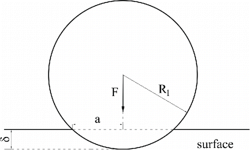
shows a sphere of radius R1 in contact with a flat surface normally with an initial velocity Vin. Hertz Citation(1896) studied the elastic impact of two spheres, and derived the following equation of pressure distribution on particle within a contact radius a:
The normal contact force P is given by[2] where mechanical parameter E* is defined as
, R* is defined as
;
,
and
are the Poisson ratio, Young's modulus, and the radius of the particle or the surface, respectively. The relative approach of the two particle centroids
is defined as
[3]
From the Hertzian theory, the limiting contact pressure at the center of the contact area in the first stage is
[4] where
is the projected radius of elastic deformation at the end of the first stage.
We now define a maximum relative approach of the two particle centroids in the first stage when
and from Equations (Equation3
[3] ) and (Equation4
[4] ) there is
[5]
During the second stage, in order to model the post-yield behavior, we assume that the contact yield stress is constant for a given impact velocity, and the radius of the contact area under plastic deformation is
and the force in annulus is the Hertzian pressure distribution. Then the normal force P2 is given as
[6] which was also obtained by Thornton and Ning Citation(1998).
Considering the conditions at yield, and combining Equations Equation(1)–(4), we obtain[7]
Substituting Equations Equation(3)[3] , Equation(5)
[5] , and Equation(7)
[7] into Equation Equation(6)
[6] , we obtain
[8]
In the third stage, the impacting process is assumed to be elastic. Then the force–displacement relationship can be described by the classic Hertzian equations with an unrecoverable relative displacement and a contact curvature
. At the point of unloading, the contact area generated by the actual maximum contact force
and reduced curvature
is the same as that developed by an equivalent elastic force
for a contact curvature of
. Hence, according to Thornton and Ning's Citation(1998) theory, we get
[9] where the equivalent elastic force is
, and
is the maximum relative approach of the two particle centroids in the whole impact process.
In addition, during elastic unloading, the contact normal force is given by
[10]
At the transition point from loading to unloading, there is , using Equations Equation(8)
[8] and (Equation10
[10] ), the plastic displacement can be written as
[11]
2.2. Dynamic model
In order to simplify the equations and obtain the dynamic model of a complete impact process, the contact radius, forces, overlap and limiting contact pressure can be normalized as follows:[12]
Then for the three stages, we have for[13] for
[14] and for
[15]
Equations Equation(13)–(15) represent the contact normal force of the three stages in turn, respectively. As the contact curvature reduced from to
in the third stage, the parameter
in Equation Equation(12)
[12] changes to
, the normalized variable
becomes
, which leads to
.
In the first stage, using the non-dimensional parameters defined in Equation Equation(12)[12] , and the normalized time defined by
, the equation of particle motion can be given by
[16]
Let be the initial velocity of the particle,
be the normalized velocity, and define
as the initial and boundary conditions, then using the method of separation of variables, the solution of Equation Equation(16)
[16] is given by
[17]
Substituting Equation Equation(12)[12] into Equation Equation(5)
[5] , we find that
.
Hence, the normalized velocity at the end of the first stage is given as
[18]
From Equation Equation(17)[17] we have
[19]
Integrating Equation Equation(19)[19] , the contact time–displacement relationship during the first stage is given as
[20]
In the second stage, using the similar method as that of the first stage, we obtain the normalized velocity–displacement relationship,[21]
At the end of the second stage, the impacting bodies have zero relative velocity. Let Equation Equation(21)[21] is equal to zero, then the normalized maximum displacement of the whole impact process
is given by
[22]
The normalized contact time during the second stage is[23]
In the third stage, the point from loading to unloading provides the initial and boundary condition for the motion of the particle, and the changes of the contact curvature must be taken into consideration. The normalized velocity is thus given by
[24]
For the plastic deformation being unrecoverable, the particle is rebounding when . Using Equation Equation(24)
[24] , we give the rebounding normalized velocity
as
[25]
The normalized contact time during the third stage is
[26]
Equations Equation(17)–(26) can be used to describe the particle's dynamic motion. For variation of particle's velocity with displacement, the simple analytical expressions can be directly calculated. As no simple expressions are available to calculate the contact time at different stages, numerical integration algorithm is adopted.
3. Test results and discussion
3.1. Restitution coefficient
The restitution coefficient is generally obtained through experiments, which in some way represents the effect of inelastic material behavior that causes energy dissipation during the impact. It is defined as a ratio of the rebound velocity to the approach velocity. The mechanisms of energy loss involved in an impact can contribute to plastic deformation, elastic wave propagation, surface forces, electrostatic effects, interfacial and internal friction, etc. Theoretical and experimental investigations indicated that the adhesion effect and the plastic deformation are the dominant factors in energy loss during low-velocity impact and high-velocity impact, respectively (Wall et al. Citation1990; Kogut and Etsion Citation2003). The present article focuses on the impacts with incident velocities higher than the yield velocity. According to the study conducted by Ning Citation(1995), the amount of energy loss in elastic waves is very low, and hence it is justified to only take into account the mechanism of plastic deformation by ignoring other minor affecting factors. The restitution coefficient can then be given by
[27]
The yield velocity , defined as the velocity below which the interaction behavior is assumed to be elastic, was originally derived by Davies Citation(1949). For a micro-particle of density
impacting onto a plane surface, the below equation holds:
[28]
If , we find that Equation Equation(27)
[27] gives
.
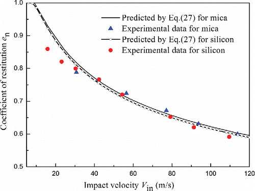
The above model was validated against Wall et al.'s Citation(1990) experimental data for silicon and mica impact surfaces and ammonium fluorescein (NH4Fl) particles of 4.9-μm diameter. The validation was performed for a range of impact velocities higher than the calculated yield velocity. Silicon and mica are hard materials with the mechanical parameter being around 1.31 GPa and 1.30 GPa, respectively. The limiting contact pressure
in this calculation is 156 MPa and 158 MPa, respectively, while the elastic yield limit Y in the literature is 74 MPa and 68 MPa for silicon and mica substrates, respectively. According to Hardy et al. Citation(1971), the limiting normal pressure
remains constant during plastic loading, where the constant
is assumed to be in the range of 2.1–2.3 in this section. Hence, the yield velocity
calculated from Equation Equation(28)
[28] is 7.59 m/s for silicon surface and 7.92 m/s for mica surface. According to Thornton and Ning's Citation(1998) theory, the maximum restitution coefficient is obtained at the yielding velocity, so the actual experimental yield velocities are much higher than the calculated ones.
The restitution coefficient obtained from Equation Equation(27)[27] is plotted against the impact velocity in . It can be seen that when the impact velocity is less than the calculated yield velocity, the impact behavior is regarded to be purely elastic. If the other mechanisms of energy dissipation are ignored, the elastic collision process is entirely reversible, hence the coefficient of restitution is unity. At high impact velocities, the plastic deformation dominates the loading process, and the initial yield force is ignorable compared to the maximum contact force. shows that the predictions in the high velocity range agree well with the experimental ones. However, the discrepancy between the predictions and the experimental ones are significant in the range of
. This can be contributed to the transition of elastic impact to fully plastic impact. While in actual impact processes, the elastic impact is not reversible and the effect of adhesion force cannot be neglected. Moreover, there exists an unresolved problem of yield stress suitable for elastic–plastic impact models in the literature (Tabor Citation1951; Johnson Citation1987). According to Ning Citation(1995), the elastic–plastic indention occurs for the mean pressure
in the range of
hence we may modify the values of
by using an appropriate
fitting the experimental data.
3.2. Effects of material properties on fraction of energy loss
The whole process of an impact can also be regarded as a gradual evolution of energy transfer. The initial energy is transformed into the elastic strain energy stored in both subjects during loading process and released to decide the movement of particle during unloading process. However, energy is also dissipated during a collision and the dissipated energy is caused by plastic deformation. The fraction of initial energy loss can then be written as follows:[29]
Variations in material properties have strong influence on the fraction of energy loss. In the following section, the effects of limiting contact pressure, Young's modulus, and density on fraction of energy loss are discussed.
3.2.1. Effect of limiting contact pressure on fraction of energy loss
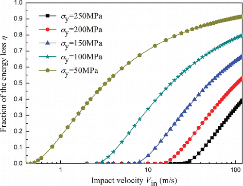
Calculations have been performed for a range of impact velocities up to 120 m/s using the properties given in Section 3.1 for silicon except that the limiting contact pressure varied from 50 to 250 MPa with a growth increment of 50 MPa. According to Equation Equation(29)[29] , shows the evolution of energy loss fraction with the impact velocity under different limiting contact pressures. It can be seen that the fraction of energy loss increases with increasing impact velocity for all five different limiting contact pressures. When the impact velocity is below the yield velocity, the fraction of energy loss remains zero for all five cases, which agrees with the above elastic impact assumption. It is evident that the fraction of energy loss increases with a decrease in the limiting contact pressure, and this phenomenon is more sensitive for lower limiting contact pressure. It is known that the plastic deformation plays a dominant role in energy loss during the high-velocity impact, while the limiting contact pressure reflects the ability to resist material deformation, hence the plastic deformation is more likely to occur for lower limiting contact pressure, which results in more energy loss during a collision.
3.2.2. Effect of Young's modulus on fraction of energy loss
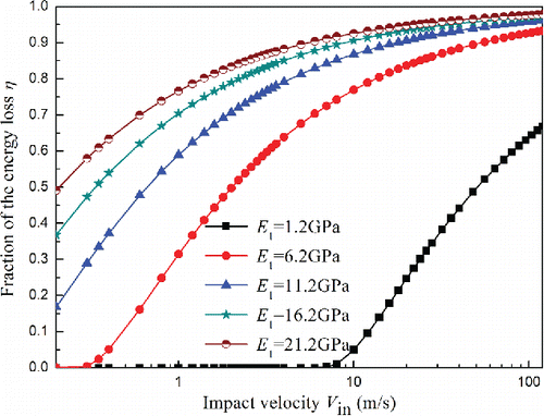
For micron-sized particles, the impact behavior is significantly affected by Young's modulus. Young's modulus is an elastic property, which depends on material structure and environmental temperature. Calculations were performed for a range of impact velocities up to 120 m/s using the parameters given in Section 3.1 for silicon except that the Young's modulus of the particle varied from 1.2 to 21.2 GPa with a single growth increment of 5 GPa and the Young's modulus of the surface remains at 150 GPa. The evolution of energy loss fraction with impact velocity under different values of Young's modulus is shown in . It can be seen that the yield velocity increases with decreasing Young's modulus. It is known that Young's modulus reflects the ability to resist elastic deformation, thus the elastic deformation decreases with an increase in Young's modulus, which will result in smaller stored elastic energy, and the energy released to furnish the movement of the particle upon rebound will become smaller. Therefore, the faction of energy loss increases with increasing Young's modulus in .
3.2.3. Effect of density for particles on fraction of energy loss
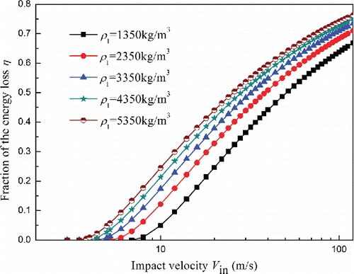
In order to study the effect of density on the fraction of energy loss, calculations were performed using the parameters given in Section 3.1 for silicon except that the density of the particle varied from 1350 to 5350 kg/m3 with a single growth increment of 1000 kg/m3. shows how the fraction of energy loss varies with the impact velocity under different densities. It is found that the yield velocity increases with decreasing density and the fraction of energy loss increases with an increase in density. This is because the inertial force increases with increasing density and accordingly will increase the energy dissipated during a collision.
3.3. Dynamic characteristics of particle impact with a flat surface
Calculations of normal impact of elastic–plastic particle onto a flat surface have been performed using the above theoretical considerations. The particle and surface properties used in this section are listed for silicon in Section 3.1.
3.3.1. Analysis of contact force and plastic displacement
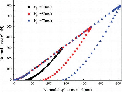
shows the normal force–displacement curves obtained for impact velocities of 30.0, 50.0, and 70.0 m/s. It was found that the slope of loading curves is consistent when the impact velocity is higher than the yield velocity. However, the elastic unloading curves are not parallel to each other for different impact velocities since the contact curvature decreases with an increase in impact velocity due to permanent deformation of contact surfaces. The permanent deformations are 69.159, 169.36, and 282.48 nm, respectively. Consequently, the slope of unloading curve at maximum displacement becomes stiffer as the severity of plastic deformation increases. In other words, the ratio of work done during elastic unloading to the work done during loading process depends on the magnitude of impact velocity, and therefore the coefficient of restitution depends on impact velocity.
Figure 6. Effect of impact velocity on the normal contact force–displacement relationship for elastic–plastic impact.
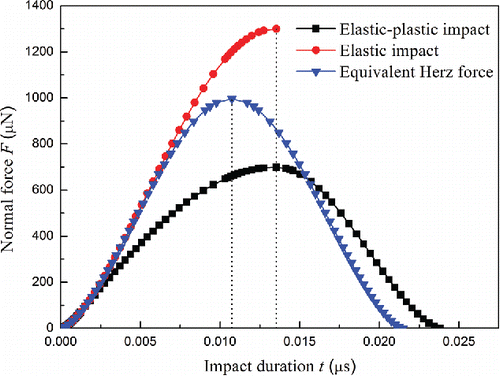
shows the evolution of the contact normal force with impact time for elastic and elastic–plastic impact, respectively. For both cases, the impact velocity is 70 m/s. A very high limiting contact pressure was adopted so that the plastic deformation can be neglected in the calculation of equivalent elastic impact. For comparison, the dependence of equivalent Hertz force on impact time during the loading process of elastic–plastic impact is also depicted. It can be seen that the contact force evolution for elastic impact is symmetrical, while for elastic–plastic impact the force evolution is asymmetric. In addition, the approaching time is significantly longer than the rebounding time for elastic–plastic impact. It is also obvious that the total contact time for elastic–plastic impact is larger than that of equivalent elastic impact.
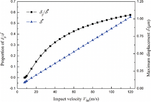
shows how the maximum displacement and the proportion of plastic displacement to the maximum displacement vary with impact velocities. It is seen that the maximum displacement increases linearly with an increase in impact velocity, while the proportion of plastic displacement to maximum displacement increases nonlinearly with an increase in impact velocity, and the slope of the proportion decreases gradually. Therefore, the energy loss increases with an increase in impact velocity.
3.3.2. Dependence of contact time on impact velocity
For a perfectly reversible elastic impact, the impact time was obtained by Deresiewicz Citation(1968), and the total contact time can be rewritten as follows:
[30]
For elastic–plastic impact, Ning Citation(1995) gives the loading time for sufficiently large impact velocity as
[31]
The contact time for the first stage t1 can be obtained by integrating Equation Equation(20)[20] numerically for
. While for
, the contact time for the second stage t2 can be obtained by integrating Equation Equation(23)
[23] . Similarly, the contact time for the third stage, which can also be called the unloading time tU, will be predicted by Equation Equation(26)
[26] for
. Therefore, the loading time can be given as
[32] and the total contact time
for the whole process can be given by
[33]
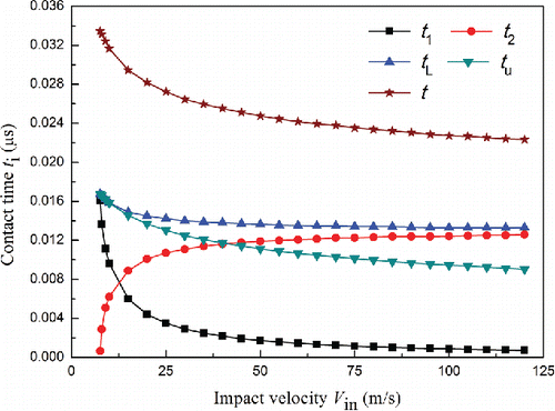
presents variation of the contact time with impact velocity. It was found that both loading and unloading time decrease with an increase in impact velocity. Thus, the total contact time decreases with an increase in impact velocity as well. For an impact velocity of 7.6 m/s, which is equal to the yield velocity, the numerical integration gave tL = 0.01671 μs and tU = 0.01675 μs, and the total contact time is 0.03346 μs, which may be compared with the theoretical prediction of 0.03348 μs according to Equation Equation(30)
[30] . It is also noted in that both the contact time t1 and t2 are sensitive to the value of impact velocity when the impact velocity is close to the yield velocity but are not significantly dependent on impact velocity when the impact velocity is larger than about 75 m/s. As can be seen from , the loading time tends to be a constant of 0.01333 μs, which is close to the prediction of 0.01307 μs by Equation Equation(31)
[31] . The difference is because Ning Citation(1995) neglected elastic deformation at initial yield, and in the material surrounding the contact point, these simplifications result in the decreasing of loading time. Therefore, it can be concluded that the numerical integration of contact time in this study can predicted as the actual impact duration.
3.3.3. Nonlinear dynamics of a particle–surface impact
The impact dynamics is investigated in terms of the evolution of normal force, particle displacement, and velocity for a typical case with obvious plastic deformation.
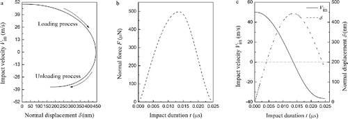
illustrates the evolution of particle velocity, displacement, and contact force during particle–surface impact with a velocity of 50 m/s. It is noted that the loading process is perfectly different from the unloading process. The particle is decelerated at the initial stage of loading process, while during unloading, the particle is accelerating as the stored strain energy releases until it is separated from the surface. The loading process starts at zero displacement but ends with a plastic deformation of 169.36 nm. During collision, the energy is dissipated because of plastic deformation. Then the rebounding velocity is 36.31 m/s as shown in . Thus, for this case the value of restitution coefficient is 0.73, which means that more than 46.71% of initial kinetic energy has been dissipated during the impact. Furthermore, it is also found that the force evolution is asymmetric, in agreement with . The loading period is 0.01365 μs, while the unloading period is 0.01115 μs in .
4. Conclusions
A dynamic model with plastic deformation has been developed to describe the elastic–plastic impact behavior of a particle indenting orthogonally with a flat surface. The theoretical model is obtained by extending the classical Hertzain theory with plastic deformation and incorporating the Newtonian equation. Some detailed conclusions achieved are as follows:
An analytic solution of restitution coefficient for normal impact has been obtained. For impact velocity higher than the yield velocity, predictions of restitution coefficient agreed well with the experimental results of Wall et al. Citation(1990).
The model can be used to discuss the effects of material properties on energy dissipation. It is found that the energy dissipation increases as the limiting contact pressure decreases but increases with increase of Young's modulus and density of particle.
The model is also capable of describing the dynamic behaviors of particle impact. The evolution of normal force for elastic–plastic impact is asymmetric, while it is symmetric for elastic impact. The predictions of total contact time and loading time are in reasonable agreement with the experimental observations made by Andrews Citation(1930).
The model can be easily coupled to numerical simulations of gas–particle flows to calculate whether the particles stick or bounce off the impacting surface.
Acknowledgments
The authors give special thanks to Professor B.P. Xu of the School of Energy and Power Engineering in Dalian University of Technology for his help with the English language.
References
- Andrews, J. (1930). LVI. Theory of Collision of Spheres of Soft Metals. Philos. Mag., 9:593–610.
- Baxter, L. L., and DeSollar, R. W. (1993). A Mechanistic Description of Ash Deposition During Pulverized Coal Combustion: Predictions Compared with Observations. Fuel, 72:1411–1418.
- Bitter, J. G. A. (1963a). A Study of Erosion Phenomena Part I. Wear, 6:5–21.
- Bitter, J. G. A. (1963b). A Study of Erosion Phenomena: Part II. Wear, 6:169–190.
- Brach, R. M., and Dunn, P. F. (1992). A Mathematical Model of the Impact and Adhesion of Microsphers. Aerosol Sci. Technol., 16:51–64.
- Brach, R. M., and Dunn, P. F. (1995). Macrodynamics of Microparticles. Aerosol Sci Technol., 23:51–71.
- Brilliantov, N. V., Spahn, F., Hertzsch, J. M., and Pöschel, T. (1996). Model for collisions in granular gases. Phy. Rev. Stat. Phys. Plasma Fluids Relat. Interdiscip. Topics, 53:5382–5392.
- Chen, S., Li, S., and Yang, M. (2015). Sticking/Rebound Criterion for Collisions of Small Adhesive Particles: Effects of Impact Parameter and Particle Size. Powder Technol., 274:431–440.
- Cheng, W., Brach, R. M., and Dunn, P. F. (2002). Three-Dimensional Modeling of Microsphere Contact/Impact with Smooth, Flat Surfaces. Aerosol Sci. Technol., 36:1045–1060.
- Dahneke, B. (1973). Measurements of Bouncing of Small Latex Spheres. J. Colloid Interface Sci., 45:584–590.
- Dahneke, B. (1975). Further Measurements of the Bouncing of Small Latex Spheres. J. Colloid Interface Sci., 51:58–65.
- Davies, R. (1949). The Determination of Static and Dynamic Yield Stresses Using a Steel Ball. Proc. R. Soc. Lond. A 197:416–432.
- Deresiewicz, H. (1968). A Note on Hertz's Theory of Impact. Acta Mechanica, 6:110–112.
- Dominik, C., and Tielens, A. G. G. M. (1997). The Physics of Dust Coagulation and the Structure of Dust Aggregates in Space. Astrophys. J., 480:647–673.
- Dong, M., Han, J., Li, S., and Pu, H. (2013). A Dynamic Model for the Normal Impact of Fly Ash Particle with a Planar Surface. Energies, 6:4288–4307.
- Hardy, C., Baronet, C., and Tordion, G. (1971). The Elasto-Plastic Indentation of a Half-Space by a Rigid Sphere. Int. J. Num. Methods Eng., 3:451–462.
- Hassanpour, A., Antony, S. J., and Ghadiri, M. (2007). Effect of Size Ratio on the Behaviour of Agglomerates Embedded in a Bed of Particles Subjected to Shearing: DEM Analysis. Chem. Eng. Sci., 62:935–942.
- Hertz, H. (1896). Miscellaneous Papers. Macmillan, London, UK.
- Johnson, K. L. (1987). Contact Mechanics. Cambridge University Press, Cambridge, UK.
- Kogut, L., and Etsion, I. (2003). Adhesion in Elastic–Plastic Spherical Microcontact. J. Colloid Interface Sci., 261:372–378.
- Lee, F., and Lockwood, F. (1998). Modelling Ash Deposition in Pulverized Coal-Fired Applications. Prog. Energy Combust. Sci., 25:117–132.
- Li, S., Marshall, J. S., Liu, G., and Yao, Q. (2011a). Adhesive Particulate Flow: The Discrete-Element Method and Its Application in Energy and Environmental Engineering. Prog. Energy Combust. Sci., 37:633–668.
- Li, F., Pan, J., and Sinka, C. (2011b). Modelling Adhesive Contact Between Fine Particles Using Material Point Method. Mech. Mater., 43:157–167.
- Liu, G., Li, S., and Yao, Q. (2011). A JKR-Based Dynamic Model for the Impact of Micro-Particle with a Flat Surface. Powder Technol., 207:215–223.
- Marshall, J. S., and Li, S. (2014). Adhesive Particle Flow: A Discrete-Element Approach. Cambridge University Press, Cambridge, UK.
- Ning, Z. (1995). Elasto-plastic Impact of Fine Particles and Fragmentation of Small Agglomerates, Aston University, Aston, UK.
- Rogers, L., and Reed, J. (1984). The Adhesion of Particles Undergoing an Elastic–Plastic Impact with a Surface. J. Phys. D, 17:677.
- Seok, J., Chun, K. M., Song, S., and Lee, J. (2014). An Empirical Study of the Dry Soot Filtration Behavior of a Metal Foam Filter on a Particle Number Concentration Basis. Energy, 76:949–957.
- Tabor, D. (1951). The Hardness of Metals. Clarendon P, Oxford, UK.
- Thornton, C., and Ning, Z. (1998). A Theoretical Model for the Stick/Bounce Behaviour of Adhesive, Elastic–Plastic Spheres. Powder Technol., 99:154–162.
- Wall, S., John, W., Wang, H.-C., and Goren, S. L. (1990). Measurements of Kinetic Energy Loss for Particles Impacting Surfaces. Aerosol Sci. Technol., 12:926–946.

