ABSTRACT
Smoothed Particle Hydrodynamics was employed in the present two-dimensional simulations, thus the algorithms implemented for both continuous and dispersed phase share a common Lagrangian stencil. The results were benchmarked against those produced in earlier investigations of particle deposition resulting from the flow around a stationary square obstacle. The proposed numerical procedure also facilitates the investigation of the fundamental physics governing the transport of resuspended particles in the wake of a moving operator, e.g., inside cleanroom facilities. Aiming to illustrate this capability, the dispersion of neutrally suspended particles behind an impulsively-started plate has been numerically simulated. Two distinct particle dispersion patterns, characterized by different Reynolds numbers, have been obtained for this problem. Altogether the results have demonstrated the accuracy of the method and associated advantages for multiphase flow studies, especially in cases involving moving boundaries due to its mesh-free nature.
Copyright © 2016 American Association for Aerosol Research
Editor:
1. Introduction
Cleanrooms provide a good example of key manufacturing facilities to many industries, such as pharmaceutics and microelectronics. The air quality in such controlled environments is vital for both human health and product quality. There, occupancy-associated particles may emanate from the human body itself (e.g., through skin shedding, breathing, coughing and sneezing) and from human activities (e.g., walking and sitting on upholstery), thus aerosolizing particles previously bound to indoor surfaces. In this context, several studies have focused on the flow pattern and resuspension of particles due to walking or floor-tapping (Fu et al. Citation2002; Kubota and Higuchi Citation2013; Oberoi et al. Citation2010; Qian and Ferro Citation2008; Qian et al. Citation2014). Such flows are characterized by Reynolds numbers in the order O(102) to O(104). Once the particles are suspended in the air, these are entrained within the fluid flow generated in the room by operator movements. The flow induced by the motions of an operator in a cleanroom was numerically investigated, e.g., by Yang and Fu (Citation2002). They have reported the formation of recirculation zones around the operator and workbench as he approached the desk. In addition, they have modeled the human body as a rectangular object.
Fluid flows around or induced by moving obstructions in confined geometries have been mostly reported for impulsively moving flat plates (Dennis et al. Citation1993; Khorasanizade and Sousa Citation2016a; Shirgaonkar et al. Citation2009) or uniformly accelerated objects (Khorasanizade and Sousa Citation2016a; Marrone et al. Citation2013). In such problems, a precise consideration of the moving boundaries constitutes an important quality factor affecting the results. In traditional mesh-based numerical methods, the treatment of such boundaries is not straightforward, often leading to significant increases in computational effort as well as to various inaccuracies. However, with the use of a new generation of numerical tools, namely the so-called meshless methods, the above-mentioned difficulties can be easily circumvented. Bearing this objective in mind, an efficient algorithm to deal with complex and moving objects has been recently proposed for Smoothed Particle Hydrodynamics (SPH) by Khorasanizade and Sousa (Citation2016a). Briefly, SPH is a particle-based method, which has originally been developed for astrophysical problems (Gingold and Monaghan Citation1977). It is based on a Lagrangian formulation, where particles are also used to represent parcels of the continuous media and these carry fluid and flow information with them throughout the simulation. In the present study, the in-house developed, semi-implicit code HAdynaSPH (Khorasanizade and Sousa Citation2014, Citation2016b) incorporating the foregoing type of boundary treatment is employed.
The objective of this investigation is twofold: first, to bring additional insight about the fundamental mechanisms involved in the problems discussed in the previous paragraphs; second, to demonstrate the capabilities of the present fully-Lagrangian, meshless method for such studies. With these aims in mind, dilute aerosol particle dispersion and deposition are benchmarked and studied here in a plane channel obstructed by either a stationary or a moving sharp-edged object. The Lagrangian equation of motion for the particles is solved in the framework of SPH. This procedure benefits from the usage of a Lagrangian formulation for both continuous and disperse phases. Aerosol particle deposition is considered for an unsteady flow regime at a fixed Reynolds number, and these results are compared with published data (Ansari et al. Citation2015; Brandon and Aggarwal Citation2001; Jafari et al. Citation2010; Li et al. Citation1994; Salmanzadeh et al. Citation2007) over a wide range of Stokes number, namely 0.001 < Stk < 10. Subsequently, aerosol particle dispersion behind an impulsively-started finite plate is studied for two different Reynolds numbers, with the goal of demonstrating the advantages of employing the SPH framework for this purpose in the presence of a moving boundary.
2. Physical and numerical details
2.1. Gas flow
The incompressible, laminar Navier–Stokes equations in Lagrangian form to be solved for the present cases are obtained following the SPH formalism. The governing equations are given by[1] where
denotes the fluid velocity vector,
is the pressure,
stand for the density and viscosity of the fluid, respectively,
represents the external forces per unit mass (e.g., gravity or other driving forces) and
is the position vector. The working fluid in the present study is considered to be air at standard atmospheric temperature and pressure conditions.
Any generic field in the flow is filtered (smoothed) with a convolution integral extended over the computational domain for the fluid domain Ω (Liu and Liu Citation2003), i.e.,
[2] where w is a weighting function, which has a compact support of size characterized by h bounded to Ω, and
represents the spatial coordinates of a generic point, whereas
denotes a spatial position inside the elementary volume
. From a physical perspective, the smoothing length h represents the characteristic length of the domain of influence of the fluid particle at the position
. General characteristics of the positive and symmetric weighting function are described in detail by Liu and Liu (Citation2003) and Monaghan (Citation2012). Taking the gradient of Equation (Equation1
[1] ) leads us to the generic form for the gradient of a function as
[3] where
stands for the derivative of w with respect to
,
is the boundary of the computational domain Ω and
indicates the normal unit vector of the boundary. The surface integral in Equation (Equation3
[3] ) vanishes if the particle's compact support is within the domain of integration, whereas in the case of near-boundary particles kernel truncation occurs. However, the latter case can be remedied by the usage of boundary particles (Liu and Liu Citation2003; Monaghan Citation2012). Following these equations, by substituting continuous fields with discrete Lagrangian domain particles carrying fluid and flow field data, the SPH scheme is obtained. In order to interpolate a field f at a calculation point i one uses the following convolution summation, which is the particle representation of Equation (Equation2
[2] ), i.e.,
[4] where i and j denote the target and its neighboring domain particle, respectively, m and ρ stand for the particle mass and density, respectively, and wij is the discrete kernel function centered on i as calculated at j. In this work, a piece-wise quintic function (Liu and Liu Citation2003) has been used here for this kernel, with a smoothing ratio of 1.3.
The differential operators appearing in the governing equations must also be expressed in accordance to the SPH formalism. Hence, the gradient of a field is given here by the formula used in (Khorasanizade and Sousa Citation2014), namely[5]
Flow incompressibility may be enforced by solving Equation (Equation1[1] ) employing a projection method (Cummins and Rudman Citation1999). In addition, the time integration scheme used in present study is of prediction—correction type (Cummins and Rudman Citation1999). For more details on the implementation of the current SPH algorithm and a suitable treatment of boundaries the reader is referred to (Khorasanizade and Sousa Citation2014, Citation2016a,Citationb). Issues on convergence, stability and consistency of the method are discussed in the Appendix.
The foregoing Lagrangian approach is markedly different from that usually followed in classical schemes (often Eulerian). briefly illustrates the merits and demerits of meshless methods versus mesh-based methods. The reader is also referred to the reviews by Gotoh and Khayyer (Citation2016), Monaghan (Citation2005), Shadloo et al. (Citation2016), and Violeau and Rogers (Citation2016) for detailed presentations and discussions on all available algorithms for SPH, the application of the method to a wide variety of complex flows and its future perspectives.
Table 1. General comparison between meshless and mesh-based numerical schemes.
2.2. Solid particle motion
The motion of aerosol particles is modeled here using the following equation (Li et al. Citation1994)[6] with
[7] where
is the gravity vector, the subscript p denotes an aerosol particle field, K = 2.594 is a constant coefficient for the Saffman lift force, dp stands for the aerosol particle diameter, τ represents the aerosol particle's relaxation time and ϵ is the particle-to-fluid density ratio. In Equation (16), Cc is the Stokes–Cunningham slip correction given by
[8] where λ represents the fluid molecular mean free path, taken as 0.066 µm for air. The various terms on the right hand-side of Equation (Equation6
[6] ) represent drag, Saffman, Brownian and gravity forces, respectively. In addition, the deformation rate tensor Sij in Equation (Equation6
[6] ) is defined as
[9]
The calculation of the Brownian contribution n(t) in Equation (Equation6[6] ) to the motion of aerosol particles is performed in accordance to the work of Li and Ahmadi (Citation1992). For each particle in the disperse phase, the time-step Δt is chosen so that the particles should have enough time to adapt to changes in the carrier phase (Hinds Citation1999), as the relaxation time is generally smaller than the SPH time-step required by numerical stability constraints. This is achieved by following the procedure described next:
Choosing an intermediate value for Δt equal to 1% of the relaxation time to ensure that the aerosol particles go through enough cycles before reaching their final stage during each iteration for the fluid flow calculation.
The SPH-time step is divided by this Δt to determine the maximum number of iterations needed by the solid particles calculations within each of the SPH iterations.
The final value of Δt results from dividing the SPH-time step by the aforementioned maximum number of iterations.
At each SPH-time step, the closest fluid particle is assigned as the “parent” of the aerosol particle and all the fluid properties are copied from former. The aforementioned Δt calculation procedure guarantees that each and every aerosol particle moves with its fluid “parent”, at least within each fluid time step. A fully-Lagrangian scheme applied to both phases enables a more accurate tracking of the environment surrounding the aerosol, as both also move within the same time interval. This becomes even more effective as no interpolation is involved in the calculation of the fluid properties at the position of the aerosol particles (Brandon and Aggarwal Citation2001). In addition, it must be mentioned that, in this investigation, a particle from the disperse phase is considered to have been deposited on a solid wall of the computational domain once its distance to this wall is within one aerosol particle radius. The foregoing particle is then removed from the domain, which implies absorption by the surface.
The aerosol particles considered in the present study are chosen to exhibit a diameter size ranging from 0.1 to 50 µm and a fixed value for ϵ = 2000. The Stokes number Stk is the key parameter characterizing their motion and it may be seen as a non-dimensionalization of the relaxation time , i.e.,
[10] where Uch and lch are a characteristic fluid velocity and a characteristic length of the flow problem, respectively. By making use of the selected size range for the aerosol particles it has been possible to examine their behavior up to the range 1.4 × 10⁻⁴ < Stk < 35, depending on the flow problem under investigation in the next section.
3. Results and discussion
3.1. Selected test cases and benchmarking
The present SPH algorithm, HAdynaSPH, has been previously validated for fluid flow (Khorasanizade and Sousa Citation2014, Citation2016a,Citationb). It is intended here to study the deposition of aerosol particles on a two-dimensional obstruction and, after benchmarking these results, to investigate also some of the fundamentals governing the transport of resuspended particles in the wake of a moving bluff body. Two basic test cases are considered, namely the flow around a stationary square obstacle (Breuer et al. Citation2000; Mukhopadhyay et al. Citation1992; Turki et al. Citation2003) and the flow produced by an impulsively-started finite plate (Dennis et al. Citation1993; Khorasanizade and Sousa Citation2016a; Shirgaonkar et al. Citation2009). Detailed analyzes of several single-phase flow solutions obtained with HAdynaSPH for these test cases have been presented earlier (Khorasanizade and Sousa Citation2016a,Citationb).
A schematic of the computational domain employed for the test cases is given in and it basically consists of an obstructed plane channel of height H. The velocity profile for fully-developed, two-dimensional laminar flow is prescribed at the inlet when (and only when) applicable to a particular case, whereas an open boundary treatment (Khorasanizade and Sousa Citation2016b) is applied at the outlet of the channel. In addition, solid walls are handled via the implementation of a special no-slip boundary treatment, denoted SBA (Khorasanizade and Sousa Citation2016a).
Figure 1. Schematic of the computational domain used in the present study.
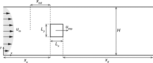
The specification of the values selected for the geometrical parameters shown in will be made within the corresponding subsection dedicated to each case. In the following, the maximum inlet flow velocity um of the parabolic profile or the impulsive velocity uimp of the finite plate (i.e., with Ly≪Lx) in an initially quiescent fluid are chosen as characteristic velocity scales, depending on the test case. However, parameter Ly is always selected as characteristic length scale. These parameters are thus used in the Reynolds number definition. In the two-phase flow simulations, aerosol particles are placed inside the domain with a uniform distribution along y on the projected area of the obstacle, at a horizontal position xinit to be given for each problem, as depicted also in .
3.2. Fluid flow and particle deposition on the obstruction
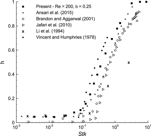
As the flow around a stationary square obstacle (i.e., with Lx /Ly = 1 and uimp = 0) has been considered elsewhere (Brandon and Aggarwal Citation2001; Jafari et al. Citation2010; Salmanzadeh et al. Citation2007) in the study of aerosol particle dispersion and deposition, our in-house ISPH method has been previously validated for this flow (Khorasanizade and Sousa Citation2016a,Citationb). Here, two-phase (one-way coupling) flow simulations have been performed in order to study the deposition of aerosol particles on the windward face of the square obstacle with a geometrical configuration corresponding to β = 0.25, xd = 6.5Ly and xu = 12.5Ly, for Re = 200. In this case, the (initial) particle resolution is Ly/10.
shows the results obtained for deposition efficiency η as a function of Stk. The parameter η has been defined as the ratio of deposited aerosol particles on the surface to the number of aerosol particles considered in each set, i.e., for each value of Stk portrayed in for the present simulations. A total of 501 aerosol particles per set have been released from the inlet section, following the procedure described in the previous subsection. It can be seen that overall good agreement has been obtained with respect to previous studies (Ansari et al. Citation2015; Brandon and Aggarwal Citation2001; Jafari et al. Citation2010; Li et al. Citation1994; Vincent and Humphries Citation1978). For values of Stk < 0.1, excellent consistency among the various investigations is observed, with the exception of the work of Jafari et al. (Citation2010). However, at higher values of Stk, nonnegligible discrepancies are found. In this range, the present data tends to indicate larger values for η than those reported in the referenced studies. Nevertheless, a tendency to overestimate η might be expected from the current modeling approach as rebound and resuspension of aerosol particles have not been accounted for.
Figure 2. Effect of Stokes number on particle deposition efficiency and comparison with results available in the literature.
3.3. Particle dispersion of resuspended particles behind a moving plate
In this subsection, two-dimensional, confined flow produced by an impulsively-started finite plate is considered. This flat plate (i.e., with Lx /Ly = 0.031) is initially at rest in a quiescent atmosphere (i.e., with um = 0) at a longitudinal station x = xu. Suddenly (no ramp function), it is subjected to motion at a constant velocity uimp along the direction perpendicular to the plate surface, aiming to crudely simulate the aerodynamic effects of a moving operator inside a cleanroom. Two different values of the Reynolds number based on the plate velocity are studied, namely Re = 20 and 126. The upstream length xu, the total channel length and the blockage ratio β are fixed to 1 Ly, 9 Ly and 0.2, respectively. In this case, the (initial) particle resolution is Ly/32. Concerning single-phase flow simulations only, the length of the downstream recirculating region formed behind the obstacle has been compared elsewhere (Khorasanizade and Sousa Citation2016a) with numerical (Koumoutsakos and Shiels Citation1996; Shirgaonkar et al. Citation2009) and experimental (Dennis et al. Citation1993) results using the present numerical method HAdynaSPH and good agreement has been reported.
Next, the motion of neutrally-suspended aerosol particles is studied in the flow induced by the movement of the plate. Aerosol particles have been placed upstream at two different stations, following the same procedure as previously described at the end of Section 3.1, so that effect of the initial separation between the aerosol particles and the plate could be investigated. The corresponding initial relative positions xinit are 0.5 Ly and 0.25 Ly upstream of the plate. Preliminary investigations have shown that particles originally placed at distances of one plate lenghtscale Ly or larger do not get entrapped within the wake, thus being only mildly affected by the motion of the plate. The range of particle size considered in these simulations ranged from ultrafine to large aerosol particles, as shown in .
Table 2. Sampling diameter of aerosol particles and corresponding Stokes number as a function of the flow problem Reynolds number.
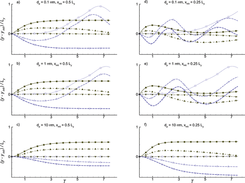
The trajectories described by aerosol particles released from a limited number of vertical locations have been studied first. These particular locations correspond to the following five vertical distances measured from the lower tip of the area projected by the plate at the release station: 0 Ly, 0.25 Ly, 0.5 Ly, 0.75 Ly and 1 Ly, henceforth denoted by VP1, VP2, VP3, VP4 and VP5, respectively. displays the trajectories of particles originating from the selected vertical locations for dp = 0.1, 1 and 10 µm. Irrespective of the flow regime set by the Reynolds number, a central jet is always produced in the fluid along the longitudinal direction, behind the moving plate. It has been found that flow fields are symmetric with respect to the central axis for both Reynolds number under investigation. Consequently, only the lower half (Re = 20) or the upper half (Re = 126) of the particle trajectories have been represented in for each of these two regimes.
Figure 3. Trajectories of resuspended aerosol particles of various sizes originating from different vertical positions at two axial stations, for Re = 20 (lower halves) and 126 (upper halves). y/Ly = 2.5 represents the axis of symmetry of the moving plate.
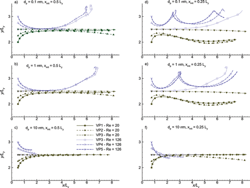
It can be seen that, at Re = 20, aerosol particles tend to converge to the axis of symmetry of the moving surface (i.e., y/Ly = 2.5). In this regime, the trajectories corresponding to aerosol particle sizes of 0.1 and 1 µm are identical, as long as the particles originated from similar spatial positions. However, at Re = 126, the aerosol particles move with markedly distinctive characteristics with respect to each other. This seems to be the result of the entrapment of smaller particles (typically with dp < 10 µm) within the recirculation region formed behind the moving plate for the higher Reynolds number. Hence, these observations apply to aerosol particles characterized by low Stokes numbers only. As the value of Stk is increased, inertia dominates the motion of the dispersed phase, hence the particles tend to move towards the axis of symmetry of the moving plate. A complementary examination of these effects can be performed with the aid of , which illustrates the dispersion of the aerosol particles along time for the various conditions studied, with respect to their vertical location of origin yinit. A closer proximity of the resuspended aerosol particles with respect to the moving surface () leads them to a more vigorous entrapment into the recirculation region formed in the wake flow. However, for large and inertial particles, as those corresponding to , a larger vertical dispersion is achieved by a decrease in the initial distance between the particles and the moving plate.
Figure 4. Vertical dispersion of resuspended aerosol particles of various sizes originating from different vertical positions at two axial stations, for Re = 20 (lower halves) and 126 (upper halves). See for legend.
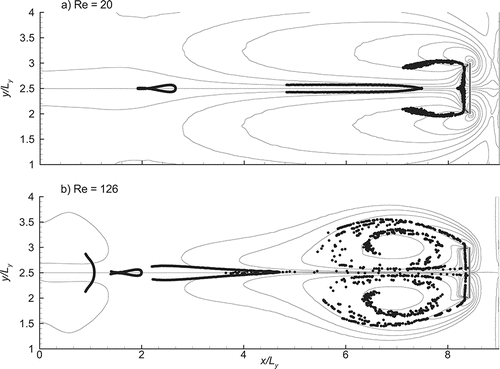
portrays the dispersion patterns of the full set of aerosol particles originating from the axial position xinit = 0.25 Ly, superimposed to the vorticity field of the fluid flow, for the same flow regimes. The represented time instant is the ending value of T in . At Re = 20, a large number of particles is carried by the central jet produced by the moving plate, but these essentially remain as elongated clumps, as depicted in . In contrast, at Re = 126, aerosol particles are seen to have mostly organized themselves along particular vorticity contours, confirming the conjecture of entrapment by the large vortical structures associated to the recirculation established behind the moving surface, as seen in . It is also interesting to note the similarity between the latter pattern and the visualization provided by Kubota and Higuchi (Citation2013) from their experiments with a tapping plate (in the separation phase), despite the absence of three-dimensional and wall effects in the present simulations.
Figure 5. Dispersion patterns of resuspended particles superimposed to the vorticity flow field produced by the motion of the plate (shown in grey), for a) Re = 20 and b) Re = 126. y/Ly = 2.5 represents the axis of symmetry of the moving plate.
For the regime characterized by Re = 126, allows a closer inspection of the region in the wake region of the moving surface, including a discrimination of particles by size. The larger values of dp in the set are not shown because these lagged considerably behind the smaller particles. In addition, for the sake of figure clarity only, some particles have been omitted from the plot in every size class. This more detailed view reveals that, whereas resuspended aerosol particles of size up to 1 µm (i.e., Stk ≤ 1.4 × 10⁻²) have been able to penetrate the inner regions of the wake vortices, larger particles mostly distribute themselves along the periphery of those structures. In fact, aerosol particles characterized by dp > 1 µm are pumped until reaching the plate, subsequently tagging along with the separated shear layer. Moreover, the larger particles shown in (i.e., dp = 6 µm) are still seen in the central jet due to their also higher inertia, slowly progressing towards the back face of the moving plate.
Figure 6. Detail of the dispersion pattern of resuspended aerosol particles behind the moving plate (shown in grey) discriminated by size for Re = 126. y/Ly = 2.5 represents the axis of symmetry of the moving plate.
4. Conclusions
A fully-Lagrangian, meshless method for the simulation of aerosol dispersion and deposition has been implemented by coupling Smoothed Particle Hydrodynamics for the continuous phase with an also Lagrangian description of the motion of the aerosol particles. The procedure was firstly validated for the deposition of aerosol particles in a channel obstruction. Good agreement with previously published data for confined flow around a two-dimensional square obstacle has been obtained.
A study on the dispersion of aerosol particles behind an impulsively-started finite plate was subsequently carried out, as an initial effort to employ the proposed method for the investigation of some of the physical mechanisms governing the transport of resuspended particles in the wake of an operator moving inside a cleanroom. Two different regimes have been identified, corresponding to two distinct Reynolds numbers, namely Re = 20 and 126. In this problem, the investigated aerosol particle diameters allowed covering the following ranges of Stokes number: 2.2 × 10⁻⁵ < Stk < 5.6 for the former regime and 1.4 × 10⁻⁴ < Stk < 35 for the latter. At the lower Reynolds number elongated clumps of particles were formed, whereas at the higher value of this flow parameter the aerosol particles were entrapped within the vortical structures established behind the moving plate. Discrimination by size class for this regime has shown that effective penetration of the vortices was achieved for particles of diameters up to 1 µm.
Funding
This work has been supported by Fundação para a Ciência e a Tecnologia (FCT), through IDMEC, under LAETA, projects PTDC/EME-MFE/103640/2008 and UID/EMS/50022/2013.
References
- Ansari, V., Goharrizi, A. S., Jafari, S., and Abolpour, B. (2015). Numerical Study of Solid Particles Motion and Deposition in a Filter with Regular and Irregular Arrangement of Blocks with using Lattice Boltzmann Method. Comput. Fluids, 108:170–178. http://dx.doi.org/10.1016/j.compfluid.2014.11.022.
- Bonet, J., and Lok, T.-S. L. (1999). Variational and Momentum Preservation Aspects of Smooth Particle Hydrodynamic Formulations. Comput. Methods Appl. Mech. Eng., 180:97–115. http://dx.doi.org/10.1016/S0045-7825(99)00051-1.
- Brandon, D. J., and Aggarwal, S. K. (2001). A Numerical Investigation of Particle Deposition on a Square Cylinder Placed in a Channel Flow. Aerosol Sci. Technol., 34:340–352. http://dx.doi.org/10.1080/02786820121279.
- Breuer, M., Bernsdorf, J., Zeiser, T., and Durst, F. (2000). Accurate Computations of the Laminar Flow Past a Square Cylinder based on Two Different Methods: Lattice-Boltzmann and Finite-Volume. Int. J. Heat Fluid Flow, 21:186–196. http://dx.doi.org/10.1016/S0142-727X(99)00081-8.
- Colagrossi, A., Bouscasse, B., Antuono, M., and Marrone, S. (2012). Particle Packing Algorithm for SPH Schemes. Comput. Phys. Commun., 183:1641–1653. http://dx.doi.org/10.1016/j.cpc.2012.02.032.
- Cummins, S. J., and Rudman, M. (1999). An SPH Projection Method. J. Comput. Phys., 152:584–607. http://dx.doi.org/10.1006/jcph.1999.6246.
- Dehnen, W., and Aly, H. (2012). Improving Convergence in Smoothed Particle Hydrodynamics Simulations without Pairing Instability. Mon. Not. R. Astron. Soc., 425:1068–1082. http://dx.doi.org/10.1111/j.1365-2966.2012.21439.x.
- Dennis, S. C. R., Qiang, W., Coutanceau, M., and Launay, J.-L. (1993). Viscous Flow Normal to a Flat Plate at Moderate Reynolds Numbers. J. Fluid Mech., 248:605–635. http://dx.doi.org/10.1017/S002211209300093X.
- Fu, W.-S., Chen, S.-F., and Yang, S.-J. (2002). A Numerical Study of the Effects of a Moving Operator on Particles in a Cleanroom with a Curtain. Aerosol Sci. Technol., 36:154–161. http://dx.doi.org/10.1080/027868202753504010.
- Gingold, R. A., and Monaghan, J. J. (1977). Smoothed Particle Hydrodynamics—Theory and Application to Non-Spherical Stars. Mon. Not. R. Astron. Soc., 181:375–389.
- Gotoh, H., and Khayyer, A. (2016). Current Achievements and Future Perspectives for Projection-based Particle Methods with Applications in Ocean Engineering. J. Ocean Eng. Mar. Energy. http://dx.doi.org/10.1007/s40722-016-0049-3.
- Hinds, W. C. (1999). Aerosol Technology: Properties, Behavior, and Measurement of Airborne Particles (2nd ed.), Ch. 5. John Wiley & Sons. http://books.google.pt/books?id=xRtSAAAAMAAJ.
- Jafari, S., Salmanzadeh, M., Rahnama, M., and Ahmadi, G. (2010). Investigation of Particle Dispersion and Deposition in a Channel with a Square Cylinder Obstruction Using the Lattice Boltzmann Method. J. Aerosol Sci., 41:198–206. http://dx.doi.org/10.1016/j.jaerosci.2009.10.005.
- Jiang, T., Ouyang, J., Li, Q., Ren, J., and Yang, B. (2011). A Corrected Smoothed Particle Hydrodynamics Method for Solving Transient Viscoelastic Fluid Flows. Appl. Math. Model., 35:3833–3853. http://dx.doi.org/10.1016/j.apm.2011.02.014.
- Jiang, T., Ouyang, J., Ren, J. L., Yang, B. X., and Xu, X. Y. (2012). A Mixed Corrected Symmetric SPH (MC-SSPH) Method for Computational Dynamic Problems. Comput. Phys. Commun., 183:50–62. http://dx.doi.org/10.1016/j.cpc.2011.08.016.
- Khorasanizade, S., and Sousa, J. M. M. (2014). A Detailed Study of Lid-Driven Cavity Flow at Moderate Reynolds Numbers Using Incompressible SPH. Int. J. Numer. Methods Fluids, 76:653–668. http://dx.doi.org/10.1002/fld.3949.
- Khorasanizade, S., and Sousa, J. M. M. (2016a). A Two-Dimensional Segmented Boundary Algorithm for Complex Moving Solid Boundaries in Smoothed Particle Hydrodynamics. Comput. Phys. Commun., 200:66–75. http://dx.doi.org/10.1016/j.cpc.2015.10.025.
- Khorasanizade, S., and Sousa, J. M. M. (2016b). An Innovative Open Boundary Treatment for Incompressible SPH. Int. J. Numer. Methods Fluids, 80:161–180. http://dx.doi.org/10.1002/fld.4074.
- Koumoutsakos, P., and Shiels, D. (1996). Simulations of the Viscous Flow Normal to an Impulsively Started and Uniformly Accelerated Flat Plate. J. Fluid Mech., 328:177–227. http://dx.doi.org/10.1017/S0022112096008695.
- Kubota, Y., and Higuchi, H. (2013). Aerodynamic Particle Resuspension Due to Human Foot and Model Foot Motions. Aerosol Sci. Technol., 47:208–217. http://dx.doi.org/10.1080/02786826.2012.742486.
- Lee, E. S., Moulinec, C., Xu, R., Violeau, D., Laurence, D., and Stansby, P. (2008). Comparisons of Weakly Compressible and Truly Incompressible Algorithms for the SPH Mesh Free Particle Method. J. Comput. Phys., 227:8417–8436. http://dx.doi.org/10.1016/j.jcp.2008.06.005.
- Li, A., and Ahmadi, G. (1992). Dispersion and Deposition of Spherical Particles from Point Sources in a Turbulent Channel Flow. Aerosol Sci. Technol., 16:209–226. http://dx.doi.org/10.1080/02786829208959550.
- Li, A., Ahmadi, G., Bayer, R. G., and Gaynes, M. A. (1994). Aerosol Particle Deposition in an Obstructed Turbulent Duct Flow. J. Aerosol Sci., 25:91–112. http://dx.doi.org/10.1016/0021-8502(94)90184-8.
- Liu, G. R., and Liu, M. B. (2003). Smoothed Particle Hydrodynamics: A Meshfree Particle Method. World Scientific Publishing Co. Pte. Ltd, Singapor.
- Marrone, S., Colagrossi, A., Antuono, M., Colicchio, G., and Graziani, G. (2013). An Accurate SPH Modeling of Viscous Flows Around Bodies at Low and Moderate Reynolds Numbers. J. Comput. Phys., 245:456–475. http://dx.doi.org/10.1016/j.jcp.2013.03.011.
- Monaghan, J. J. (2005). Smoothed Particle Hydrodynamics. Rep. Progr. Phys, 68(8):1703–1759. http://dx.doi.org/10.1088/0034-4885/68/8/R01.
- Monaghan, J. J. (2012). Smoothed Particle Hydrodynamics and Its Diverse Applications. Annu. Rev. Fluid Mech., 44:323–346. http://dx.doi.org/10.1146/annurev-fluid-120710-101220.
- Mukhopadhyay, A., Biswas, G., and Sundararajan, T. (1992). Numerical Investigation of Confined Wakes Behind a Square Cylinder in a Channel. Int. J. Numer. Methods Fluids, 14:1473–1484. http://dx.doi.org/10.1002/fld.1650141-208.
- Oberoi, R. C., Choi, J.-I., Edwards, J. R., Rosati, J. A., Thornburg, J., and Rodes, C. E. (2010). Human-Induced Particle Re-Suspension in a Room. Aerosol Sci. Technol., 44:216–229. http://dx.doi.org/10.1080/02786820903530852.
- Patil, P. P., and Tiwari, S. (2008). Effect of Blockage Ratio on Wake Transition for Flow Past Square Cylinder. Fluid Dyn. Res., 40:753–778. http://dx.doi.org/10.1016/j.fluiddyn.2008.04.001.
- Qian, J., and Ferro, A. R. (2008). Resuspension of Dust Particles in a Chamber and Associated Environmental Factors. Aerosol Sci. Technol., 42:566–578. http://dx.doi.org/10.1080/02786820802220274.
- Qian, J., Peccia, J., and Ferro, A. R. (2014). Walking-Induced Particle Resuspension in Indoor Environments. Atmos. Environ., 89:464–481. http://dx.doi.org/10.1016/j.atmosenv.2014.02.035.
- Salmanzadeh, M., Rahnama, M., and Ahmadi, G. (2007). Particle Transport and Deposition in a Duct Flow with a Rectangular Obstruction. Part. Sci. Technol., 25:401–412. http://dx.doi.org/10.1080/02726350701487181.
- Shadloo, M. S., Oger, G., and Le Touzé, D. (2016). Smoothed Particle Hydrodynamics Method for Fluid Flows, Towards Industrial Applications: Motivations, Current State, and Challenges. Computers & Fluids, 136:11–34. http://dx.doi.org/10.1016/j.compfluid.2016.05.029.
- Shahriari, S., Hassan, I. G., and Kadem, L. (2013). Modeling Unsteady Flow Characteristics Using Smoothed Particle Hydrodynamics. Appl. Math. Model., 37:1431–1450. http://dx.doi.org/10.1016/j.apm.2012.04.017.
- Shirgaonkar, A. A., MacIver, M. A., and Patankar, N. A. (2009). A New Mathematical Formulation and Fast Algorithm for Fully Resolved Simulation of Self-Propulsion. J. Comput. Phys., 228:2366–2390. http://dx.doi.org/10.1016/j.jcp.2008.12.006.
- Turki, S., Abbassi, H., and Nasrallah, S. B. (2003). Effect of the Blockage Ratio on the Flow in a Channel with a Built-in Square Cylinder. Comput.Mech., 33:22–29. http://dx.doi.org/10.1007/s00466-003-0496-2.
- Vincent, J. H., and Humphries, W. (1978). The Collection of Airborne Dusts by Bluff Bodies. Chem. Eng. Sci., 33:1147–1155. http://dx.doi.org/10.1016/0009-2509(78)85021-0.
- Violeau, D., and Rogers, B. D. (2016). Smoothed Particle Hydrodynamics (SPH) for Free-Surface Flows: Past, Present and Future. J. Hydraul. Res., 54(1):1–26. http://dx.doi.org/10.1080/00221686.2015.1119209.
- Xu, R., Stansby, P. K., and Laurence, D. (2009). Accuracy and Stability in Incompressible SPH (ISPH) Based on the Projection Method and a New Approach. J. Comput. Phys., 228:6703–6725. http://dx.doi.org/10.1016/j.jcp.2009.05.032.
- Yang, S.-J., and Fu, W.-S. (2002). A Numerical Investigation of Effects of a Moving Operator on Airflow Patterns in a Cleanroom. Build. Environ., 37:705–712. http://dx.doi.org/10.1016/S0360-1323(01)00080-4.
Appendix
Stability is of crucial importance for a reliable application of any numerical method to engineering problems. The maximum allowable time step for the considered Reynolds number range is set by the Courant–Friedrichs–Lewy, thus enhancing the stability of SPH (Gotoh and Khayyer Citation2016). The use of a corrective method to reconstruct the kernel consistency, especially in the vicinity of the boundaries, can further improve the stability and consistency of the numerical scheme (Bonet and Lok Citation1999; Jiang et al. Citation2011, Citation2012). In addition, choosing the appropriate kernel with an optimized size of the compact support also plays an important role as pointed out by Colagrossi et al. (Citation2012), and Dehnen and Aly (Citation2012). Moreover, artificial shifting of the position of the particles has also demonstrated to be an effective remedy for numerical instabilities in fully-incompressible SPH (Khorasanizade and Sousa Citation2016b; Xu et al. Citation2009).
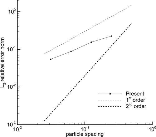
The -norm of the relative error is often used to examine the convergence of a numerical method. Here, this norm has been calculated to assess the average relative error in the length of the recirculating bubble
formed behind the impulsevily moving plate at Re = 20, i.e.,
[A1] where N represents number of samples in time, which is equal to 16 in the present study. The reference data
is taken from the work of Dennis et al. (Citation1993). shows the evolution of the
-norm of the relative error as a function of the normalized particle spacing. The rate of convergence approaches that of a first-order accurate method, which is similar to the findings of other researchers (Lee et al. Citation2008; Shahriari et al. Citation2013; Gotoh and Khayyer Citation2016).
Figure A1. -norm of the relative error in the length of the recirculation bubble formed behind the impulsively moving plate at Re = 20 as a function of the normalized particle spacing.