ABSTRACT
A quartz crystal microbalance (QCM) based instrument has been developed for real-time aerosol mass distribution measurement. It includes two key components: a six-stage QCM micro-orifice cascade impactor and a novel relative humidity (RH) conditioner. This instrument operates at a flow rate of 10 L·min−1 and measures the mass of the collected particles in six aerodynamic diameter channels between 45 nm and 2.5 μm. The RH conditioner ensures that the aerosol particles are collected at an RH between 40% and 65%, which is critical for eliminating particle bounce and for ensuring optimal particle coupling with the QCM. The nozzles of the impactors are clustered in the center of the nozzle plates. Therefore, particles are deposited on the central electrode of the QCM, where the mass calculated from first principles (i.e., Sauerbrey equation) agrees with the actual collected mass. The QCM response is linear up to around 130 μg for solid particles and up to around 2 μg for liquid particles. The collection efficiency curves of the QCM impactor stages were measured experimentally with monodisperse aerosols, and the results agree with the predictions of established impactor theory. This QCM-based instrument has also been tested with ambient aerosols with varying temperature and relative humidity. The aerosol distributions measured by this new instrument are in good agreement with simultaneous independent measurements carried out with a wide-range particle spectrometer (MSP Model 1000XP WPS).
Copyright © 2016 American Association for Aerosol Research
EDITOR:
1. Introduction
Cascade impactors are widely used instruments for measuring particle mass distributions (Marple Citation2004; Chow and Watson Citation2007). They collect size-fractionated particles by inertial impaction. They can cover a very wide particle size range from a few nanometers to tens of micrometers (Vanderpool et al. Citation1987; Marple et al. Citation1991; de la Mora and Schmidt-Ott Citation1993; Ude and de la Mora Citation2003; Arffman et al. Citation2015). Traditional impactors typically require sampling for long periods of time, so that the aerosol mass collected on the impaction substrate of each stage can be weighed, and can also be used for quantitative chemical composition analysis (Fang et al. Citation2014; Olson et al. Citation2014).
Several cascade impactors with real-time measurement ability have been developed during the past few decades. One approach incorporates a multichannel electrometer into the impactor (Keskinen et al. Citation1992). Sampled particles are first unipolarly charged with a corona charger at the inlet. When the particles impact the electrically isolated impaction plates, each electrometer channel reads the current. The current readings can then be used to calculate the particle concentration (Takahashi, Citation1972; Tropp et al. Citation1980; Keskinen et al. Citation1992). These instruments measure particle number distribution instead of mass distribution, but they have the advantage of a very fast response (seconds). Converting electrical current to particle concentration, however, requires accurate information on the size-dependent charging efficiency, which depends on the charger design and requires calibration (Keskinen et al. Citation1992; Chen and Pui, Citation1999). Previous calibrations show that the dependence of charging efficiency on particle size and concentration may impair the performance of electrometer-based impactors (Marjamäki et al. Citation2000; Järvinen et al. Citation2014). The aging of the charger can cause additional errors (Marjamäki et al. Citation2000; Järvinen et al. Citation2014).
The other approach to real-time mass measurement utilizes quartz crystal microbalances (QCMs; Chuan Citation1970; Chuan Citation1974; Marple et al. Citation1986). QCMs are flush-mounted to the impaction plates. After aerosol particles impact on the QCMs, the resonance frequencies of the QCMs decrease proportionally to the mass added. The mass of the aerosol particles can be calculated from the frequency shift using the Sauerbrey equation (Sauerbrey Citation1959) (Equation (Equation1[1] )).
[1]
In this equation, Δf is the frequency change of the QCM, A is the active area of the crystal (1.27 cm2), ρq is the density of the quartz (2.65 g · cm−3), µq is the shear modulus of quartz for AT-cut crystal (2.947 × 10¹¹ g · cm−1 · s−2), and f0 is the resonant frequency (6.0 MHz). Since the boundary conditions of the Sauerbrey equation cannot be fully satisfied at the edge of the QCM, the mass sensitivity at the edge is poorer than that predicted by the Sauerbrey equation (Hering Citation1987; Cumpson and Seah Citation1990). More recent QCMs, on the other hand, can be designed to minimize the off-center mass sensitivity, making their response closer to the prediction of the Sauerbrey equation. Another advancement in the QCM technology includes the introduction of highly stable and sensitive electronic monitors using impedance measurement to obtain sub-Hz resolution in frequency measurement (Wudy et al. Citation2008), thus enabling nanogram mass resolution.
A significant concern when operating a cascade impactor is particle bounce (Marple et al. Citation2001). Also, for QCM measurements, a deficient coupling of collected particles on the QCM surface (i.e., failure of deposited particles to oscillate with the crystal) is another source of error (Sauerbrey Citation1959). An accurate impactor measurement requires particle bounce to be completely eliminated and that the collected particles are rigidly attached (i.e., coupled) to the surface of the crystal. Various methods have been developed to eliminate particle bounce, including coating the substrate with grease or oil (Turner and Hering Citation1987; Pak et al. Citation1992), using a porous material as substrate (Huang et al. Citation2001; Kavouras and Koutrakis Citation2001), and conditioning the RH of the sampled aerosol (Winkler Citation1974; Stein et al. Citation1994; Vasiliou et al. Citation1999; Bateman et al. Citation2014).
The real-time measurement system introduced in this work benefits from the new technological advancements in the QCMs. It also relies on a novel RH conditioner to maintain the RH of the incoming aerosol in the range of 40% to 65% regardless of the RH at the inlet of the instrument. The design of the real-time mass measurement system is discussed in the following sections, including the validation of the RH conditioner and the QCMs, the experimental determination of the collection efficiency curve as a function of particle diameter for each stage of the cascade impactor, and the quantification of its real-time measuring ability with outdoor aerosols (Shoreview, MN). This instrument provides a practical solution for real-time aerosol mass distribution measurement that is simple and robust.
2. Description of the aerosol mass distribution measurement instrument
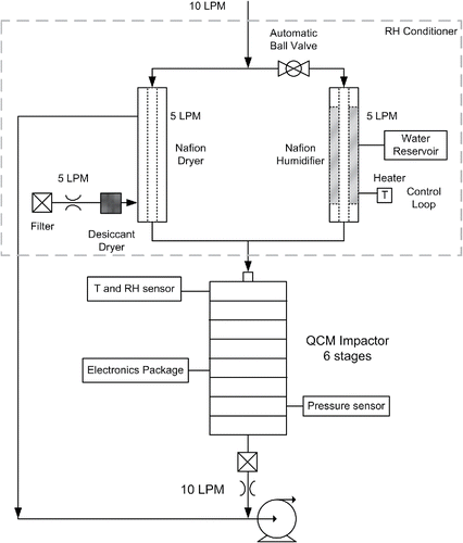
is a schematic diagram of the complete instrument. The aerosol flow of 10 L·min−1 is sampled at the inlet and routed through the RH conditioner before getting to the six-stage QCM impactor. The electronics package includes six precision oscillators/frequency monitors that measure the resonant frequencies of the QCMs and transmit their values to the computer. Additional electronics include programmable logic to receive the output from temperature, humidity, and pressure sensors and send control commands to the ball valve and to the heater. A software package in the computer controls measurement runs according to user specifications and acquires frequency and sensor outputs. Key components of the instrument are described below.
Figure 1. Schematic diagram of the real-time mass distribution measuring instrument. An external pump is used to draw the 10 L · min−1 inlet flow and the 5 L · min−1 sheath flow for the dryer. Two critical orifices are used to control the two flow rates.
2.1. Relative humidity conditioner
The dashed line box in shows the RH conditioner. The ball valve is automatically controlled according to the RH at the cascade impactor inlet. If the RH is in the medium or low range (), the ball valve is open. The flow is split evenly between the Nafion™ (Perma Pure LLC, Lakewood Township, NJ, USA) dryer and the Nafion™ humidifier. The dryer and the humidifier consist of a 12-inch-long and a 6-inch-long Nafion™ tube, respectively, each with the inner diameter of 0.7 inch (18 mm). The larger diameter of these Nafion™ tubes minimizes the aerosol particle losses. The outside jacket of the humidifier tube is filled with water, whose temperature is controlled automatically based on the humidity at the inlet of the QCM impactor. On the other hand, a 5 L · min−1 flow of dry clean air is maintained in the outer jacket of the Nafion™ dryer (). The two air streams exiting the dryer and the humidifier are mixed before the inlet of the QCM impactor.
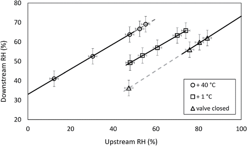
Figure 2. Performance of the RH conditioner. +40°C and +1°C represent the operational set point of the heater as 40°C and 1°C above the temperature at the QCM impactor inlet. The symbols represent measured RH values. The dark solid lines represent the actual operating regions of the RH conditioner. The gray dashed lines are linear fittings of the experiment data points.
2.2. Quartz crystal microbalances
The QCMs installed in the impactor are AT-cut planar-convex quartz crystals of 1.0 in (25.4 mm) diameter. They have wrap-around gold-coated electrodes. Their resonant frequency is 6 MHz. Electrical contacts to both top and bottom electrodes are made from the bottom of each crystal. The top surface of the quartz crystal is flush-mounted, and the crystal is glued to the plastic impaction plate, which is mounted on a pedestal by two small screws. Impaction plates can be easily cleaned or replaced. The diameter of the QCM gold electrode (where the mass sensitivity is in accord with theory) is 0.50 in (12.7 mm). The nozzles are clustered in this same region to deposit all the particles on this area (see Section 6). During operation, the frequency change of each QCM is monitored and recorded.
2.3. The QCM impactor
The mechanical design of the QCM cascade impactor is based on the model 125R MOUDI-II from MSP Corporation (Shoreview, MN, USA). The design and operating parameters are listed in . The sample inlet flow rate is 10 L · min−1, and the number of nozzles for each stage are one third of the original MOUDI nozzle plates designed by Marple et al. (Citation1991). The pressure ratio at each stage is based on actual pressure measurements. The 50% cutpoint (D50), value of SQRT (St50), and geometric standard deviation (σg) of each impactor stage are the experimentally obtained values as explained in the calibration section of this article.
Table 1. QCM cascade impactor design and operating parameters.
3. RH conditioner evaluation
The function of the RH conditioner is to control the RH of the sampled aerosol between 40% and 65%. The RH conditioner is controlled according to the RH at the QCM impactor inlet downstream, in three operating modes, as shown in . The symbols represent the experimental data points. In actual operation, the conditioner operates along the dark lines. The gray dashed lines were fitted to the experimental data points to establish the experimental performance of each mode of operation. When the system starts, it runs at the “+ 1°C” mode (i.e., the set point of the heater for the water jacket of the humidifier is 1°C above the temperature at the impactor inlet). The 1°C difference is used to compensate for the latent heat loss caused by water evaporation. In this operating mode, if the downstream RH drops below 48%, the conditioner switches to the “+ 40°C” mode to add more moisture into the aerosol stream. If the downstream RH rises above 65%, the ball valve automatically closes (i.e., “valve closed” mode), routing the entire sample flow through the dryer. In each operating mode, the relationship between upstream and downstream RH is linear. Therefore, as long as the RH at the QCM impactor inlet (downstream of the RH conditioner) is known, monitoring the upstream RH is really not necessary. The flow streams coming out from the two Nafion™ tubes mix at a stainless steel tee, which connects with the QCM cascade impactor by stainless steel tubes. These metallic components, because of their high thermal conductivity, allow adequate cooling of the sample before it reaches the QCM impactor. Thus, even in the “+ 40°C” operating mode, the temperature at the impactor inlet is still approximately equal to the room temperature, with a variation smaller than 1°C. also shows that, except for the extremely wet or dry conditions, the downstream RH is always in the 40% to 65% range. Section 4 of this article shows that 40% RH is adequate to obtain good coupling of the solid particles on the QCM impaction plate. Conditioning the incoming aerosol to RH values higher than 65% may induce some operational problems. One is that hygroscopic particles can grow as they are accelerated through the nozzles (air temperature goes down, which further increases the RH) (Flagan Citation1982; Arffman et al. Citation2011). Water can then condense on the particles making them bigger. This effect becomes significant when the RH is higher than about 80% (Fang et al. Citation1991). The other problem is that the mass of hygroscopic particles cannot be accurately measured by the QCM when the RH is close to their deliquescence point. See Section 4 and the online supplementary information (SI) for more details. To prevent inadequate particle coupling and bounce, the alternative approach of coating the QCM with a thin layer of silicone oil (Pak et al. Citation1992) was also considered in this work. This approach was more labor intensive, and the air flow coming out from the nozzles gradually pushed the anti-bounce layer away from the central electrodes of the QCMs, which eventually lead to erroneous mass measurements.
4. QCM performance validation
Previous studies suggest that RH values up to 70% may be needed to prevent particle bounce (Stein et al. Citation1994; Chen et al. Citation2011). In this section, we show that RH values between 40% and 65% are adequate for eliminating bounce and for ensuring proper coupling of the particles collected on the QCM surface for several solid materials (polystyrene latex spheres, ammonium sulfate, and sodium chloride). The results also show that, in this case, the Sauerbrey equation gives an accurate estimation of the collected mass.
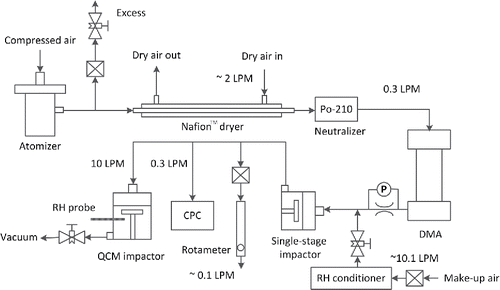
shows the setup for determining the experimental performance of the selected QCMs. Polystyrene latex spheres (PSL), ammonium sulfate, sodium chloride, and oleic acid particles were generated from a Collison-type atomizer. A Nafion™ dryer was used after the atomizer to remove moisture from the aerosol stream, and a Po210 neutralizer was used to impart an equilibrium bipolar charge distribution to the aerosol. A differential mobility analyzer (DMA) was then used to select monodisperse particles. The filtered make-up air was conditioned to a known relative humidity value. Its flow rate was not directly measured, but was adjusted so that about 0.1 L · min−1 flow was vented through the rotameter. Since the make-up air flow rate was more than 30 times larger than the aerosol flow rate from the DMA, its RH controlled the RH at the impactor inlet, which was measured by a capacitive relative humidity sensor. A conventional single-stage impactor was used to remove any larger multiply charged aerosol particles that had the same electrical mobility as the singly charged ones. For example, if the DMA was selecting 500 nm particles, then the 510 nm cutpoint nozzle plate was used to remove the doubly charged particles. In this case, some 500 nm particles coming out from the DMA were also removed, but the remaining aerosol was truly monodisperse (Romay-Novas and Pui Citation1988). The tested impactor stage was selected so that it has the largest available cutpoint to collect nearly 100% of the monodisperse aerosol. For example, if the aerodynamic diameter of the challenging particle was 800 nm, then a 510 nm cutpoint stage, instead of 305 nm or lower, would be used in the QCM impactor, since, in a real application, these particles will all be collected on the 510 nm stage. The monodisperse aerosol number concentration was measured at the inlet of the impactor with a condensation particle counter (CPC) previously calibrated with an electrometer. The flow rate entering the QCM impactor was adjusted by a flow control valve at the exit of the impactor. For each test the flow rate at the inlet of the QCM impactor was measured by a calibrated flow meter (TSI Model 4140).
For each type of particle, several RH values were tested. The RH values ranged between 30% and 90%. The total mass of particles sampled by the QCM impactor stage was estimated by the Sauerbrey equation (Equation (Equation1[1] )) according to the measured frequency change of the QCM (no calibration factor was needed). Since these particles after the DMA are highly monodisperse with a known density and charge, their total mass can also be estimated based on the number concentration measured by the CPC using Equation (Equation2
[2] ):
[2]
In Equation (Equation2[2] ), Qimpactor is the sample flow rate of the QCM impactor (i.e., 10 L · min−1), t is the total sampling time, N is the particle concentration measured by CPC, ρ is the density of the particles, and Vp is the volume of the particle. PSL and oleic acid particles were spherical. Ammonium sulfate particles generated by the atomizer could also be assumed to be spherical (Zelenyuk et al. Citation2006). Sodium chloride particles were assumed to be cubic and with a shape factor of 1.08 for calculating their volume (Zelenyuk et al. Citation2006). shows the comparison between the masses calculated from Equations Equation(1) and (2). All the data points in were collected with the RH at the inlet of the impactor stage between 40% and 50%. The fact that the data points align on the one to one line demonstrates that particle bounce is effectively eliminated. Since the CPC measures all the particles, if particle bounce were significant, the mass calculated by the CPC would be higher than the mass calculated from the QCM impactor. In other words, the data points would appear below the dashed line. For the solid particles, the mass value on the vertical axis is the total mass collected at the end of each test. The good agreement between CPC and QCM impactor was observed from the beginning to the end of each test. The masses calculated by the two equations usually agree with each other with a discrepancy smaller than 10% (Figures S1 to S4). Each data point in represents a complete test like the ones showed in Figures S1 to S4. The maximum amount of mass collected on the QCM during these tests was around 130 μg for 700 nm ammonium sulfate particles. The mass sensitivity of the QCM still did not change at that point. Bounce of solid particles started to appear when the RH was below 40% and became significant when RH reached 30%. For oleic acid particles, the “X” symbol in (around 2.2 μg) shows the maximum mass that could be accurately measured. Beyond this point, a liquid layer of oleic acid would form on the QCM, and effects due to liquid density, viscosity, and conductivity started to become important (Kanazawa and Gordon Citation1985; Rodahl et al. Citation1996). The Sauerbrey equation did no longer apply for larger mass loadings of liquid oleic acid particles.
Figure 4. Comparison of the QCM-based aerosol mass measurement with CPC-based mass. Horizontal axis shows the total mass calculated by Equation (Equation2[2] ). Vertical axis shows the total mass calculated by Equation (Equation1
[1] ). The particle sizes are mobility diameters. The horizontal uncertainty comes from the counting efficiency of the CPC, which is less than 3%. The vertical uncertainty comes from the noise of the QCM frequency, which corresponds to about 25 ng in mass. All the data points in the figure were collected in the RH range between 40% and 50%. The comparisons between the two methods during the test as a function of time for the data points of 700 nm ammonium sulfate, 364 nm sodium chloride, 500 nm PSL, and 700 nm oleic acid are shown in Section S1 of the online supplementary information as examples.
![Figure 4. Comparison of the QCM-based aerosol mass measurement with CPC-based mass. Horizontal axis shows the total mass calculated by Equation (Equation2[2] ). Vertical axis shows the total mass calculated by Equation (Equation1[1] ). The particle sizes are mobility diameters. The horizontal uncertainty comes from the counting efficiency of the CPC, which is less than 3%. The vertical uncertainty comes from the noise of the QCM frequency, which corresponds to about 25 ng in mass. All the data points in the figure were collected in the RH range between 40% and 50%. The comparisons between the two methods during the test as a function of time for the data points of 700 nm ammonium sulfate, 364 nm sodium chloride, 500 nm PSL, and 700 nm oleic acid are shown in Section S1 of the online supplementary information as examples.](/cms/asset/973efa26-42cd-4d7a-b5f1-6a45068ec429/uast_a_1213790_f0004_b.gif)
During the tests when the RH was higher than 65%, results for PSL particles did not change. However, for hygroscopic particles (i.e., sodium chloride and ammonium sulfate) when the RH was close to their deliquescence RH points, they appeared to absorb water and went through some phase transition. The deposited particles decoupled from the QCM within seconds. The resonance frequency of the QCM rose significantly as if the majority of the collected mass disappeared. (See the SI for more details.)
5. Calibration of the QCM impactor stages
The QCM impactor was calibrated with monodisperse particles of known aerodynamic diameter using two different experimental techniques. For the inlet and first stage of the impactor, a flow-focusing monodisperse aerosol generator (FMAG) (Duan et al. Citation2016) was used to generate highly monodisperse oleic acid particles containing uranine dye (i.e., fluorescein sodium, C20H10Na2O5) as a tracer. To completely eliminate the small fraction of doublets produced by the FMAG, a multiplet reduction impactor (Siegford et al. Citation1994) was used. The calibration procedure used was similar to that reported by Pui et al. (Citation1987), and Marple et al. (Citation1991, Citation2003). The fraction of the particles collected by the impactor stage was determined by the fluorometric method. For each calibration point, particles of the desired size were generated and sampled for about 20 to 30 min. Then, the particles on the impaction plate and internal impactor surfaces (including the back side of nozzle plate) were carefully wiped with cotton swabs. The particles exiting the impactor stage were collected by a high-efficiency downstream filter (i.e., PALL A/E glass fiber). The cotton swabs and the downstream filter were then washed in clean beakers containing 50 mL of 0.001 N aqueous sodium hydroxide solution until the uranine dye was completely dissolved. A digital fluorometer (Model 450, Turner Designs, Sunnyvale, CA, USA) was used to measure the relative fluorescence signal intensity of each solution. The collection efficiencies were determined quantitatively by comparing the signal from the impaction plate deposits with all the other deposits. Particle losses on the walls and on the back side of the stage 1 nozzle plate were also measured and found to be negligible (<1%). No particle bounce was observed as the particles were liquid and the collection efficiency curves approached nearly 100%.
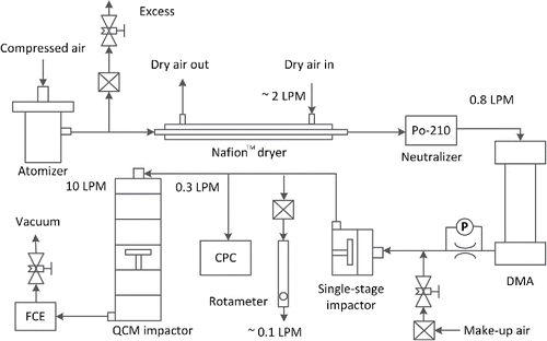
Calibration of stages 2 to 6 was accomplished with an improved technique as compared with the one described by Marple et al. (Citation1991). shows the schematic of the calibration setup. Liquid DEHS (Di (2-ethylhexyl) sebacate, ρ = 0.914 g cm−3) particles were generated with a Collison-type atomizer. The concentration of the DEHS in isopropyl alcohol solution was varied depending on the stage being calibrated (i.e., 1% for stages two and three, 0.3% for stages four and five, and 0.1% for stage six). A differential mobility analyzer (i.e., DMA) of conventional length (MSP Mini-DMA) was used to select particles of the same electrical mobility for calibrating stages 2 to 5. A nano-DMA (MSP Nano-DMA), with a shorter mobility classification length was used for calibrating stage 6. Both DMAs were first calibrated with NIST-traceable PSL particles. The DMAs were operated with 5.0 L · min−1 sheath flow rate and 0.8 L · min−1 aerosol flow rate. A single-stage impactor was also used to remove multiply charged particles from the DMA (Romay-Novas and Pui Citation1988). Downstream of the single-stage impactor the flow was split into three streams, about 0.1 L · min−1 was vented through the rotameter, 0.300 L · min−1 went to the CPC, and 10.0 L · min−1 went to the QCM impactor. Since the single-stage impactor could have a significant pressure drop, the excess flow through the rotameter ensured that the inlet of the QCM impactor was always at ambient pressure (about 98 kPa for Shoreview, MN, USA). The CPC measured the particle number concentration upstream of the QCM impactor. A Faraday cage electrometer (FCE) was used to measure the particle number concentration downstream of QCM impactor simultaneously. All the nozzle plates were always installed in the QCM cascade impactor to make sure that the pressure at the stage under calibration was at its normal operating condition. Only the impaction plate of the stage being calibrated was installed for each test. The volumetric flow rate at the inlet of QCM impactor was controlled at 10.0 L · min−1 and was measured before and after each test. To ensure optimum particle capture upon impact the surfaces of the impaction plates were coated with Silicone oil (product number 181838, Dow Corning Corporation, Auburn, MI, USA) and baked for about 2 h at 90°C before each test. Before each measurement, the impaction plate of the stage under calibration was removed and the aerosol number concentrations from the CPC and the FCE were compared to ensure they agree within about 3%. The difference between the CPC and the FCE also indicated that the inter-stage particle losses for the particle size range tested (30 nm to 600 nm) were low (below 3%). If particle losses by diffusion were significant inside the QCM impactor, a larger discrepancy between the CPC reading and the FCE reading would have been observed. Compared with previous calibrations, the particle concentration upstream and downstream of the stage in each test was simultaneously monitored in this setup. The correct operating pressure was created by installing all the nozzle plates above the calibration stage, instead of using an additional needle valve (Marple et al. Citation1991). Therefore, possible errors due to the temporal change of the particle concentration and any particle losses inside the needle valve were eliminated.
The collection efficiency curves obtained for the inlet and the six stages of the QCM impactor are shown in . The main calibration results are also summarized in . The geometric standard deviation (σg), which is a measure of the sharpness of the efficiency curve, is defined as the square root of the particle diameter at the 84% efficiency to the particle diameter at the 16% efficiency. The Reynolds and Stokes numbers are defined as follows:[3]
[4]
Figure 6. Collection efficiency curves for the QCM impactor inlet and six stages. Solid lines are the cumulative lognormal distribution functions fitted to the experimental data points.
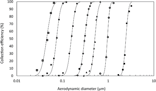
In Equations Equation(3) and (4), ρg is the air density, W is the nozzle diameter, U is the average air velocity, μ is the air absolute viscosity, Q is volumetric flow rate, Cc is the slip correction factor, dp is the particle aerodynamic diameter, and n is the number of nozzles on each stage. St50 is the Stokes number at the 50% cut size. The simulation work of Rader and Marple (Citation1985) showed that for T/W equals 1, SQRT(St50) is about 0.48 for S/W of 1 and approaches 0.50 for larger values of S/W. SQRT(St50) also decreases when T/W increases (Marple Citation1970). For stages 1 and 2, the S/W values are about 1. Their SQRT(St50) values of 0.46 and 0.47 are very close to the theory prediction of 0.48. For the lower stages, both S/W and T/W values are larger than 1. Their St50 values are between 0.47 and 0.51, still in good agreement with theoretical predictions. The steepness of the stage efficiency curves (i.e., σg) are between 1.10 and 1.24, with the larger value at the largest jet-to-plate distance. The QCM impactor cutpoints are smaller than the corresponding cutpoints of the original MOUDI impactor stages (Marple et al. Citation1991). It is probably because of the fact that S/W values of the QCM impactor are smaller, particularly for stages 5 and 6. Similar dependence of cutpoints on S/W has been reported in previous work (Tsai et al. Citation2012; Liu et al. Citation2013).
6. Aerosol sampling at outdoor environment
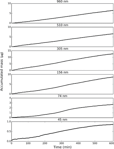
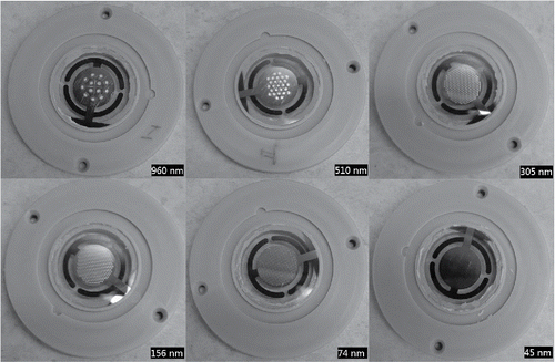
Ambient outdoor evaluations of the Aerosol Mass Distribution Measurement System were carried out at the parking lot outside of MSP Corporation (Shoreview, MN, USA). shows the mass change on each stage as a function of time for a sampling period of about 10 h. shows the photos of the impaction plate of each stage after the test. The QCMs are at the center of the impaction plates with well-defined particle deposits on the gold electrodes.
Figure 8. Particle deposition on each stage after 10 h of ambient air sampling. Cutpoint of each stage is shown on the bottom right corner.
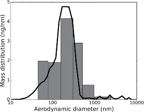
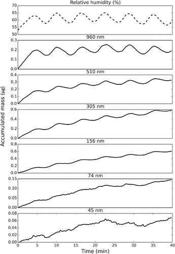
A meaningful measurement of this QCM-based instrument requires collecting mass significantly larger than the noise level of 25 ng on any one of the six QCM stages. For a measurement with a signal-to-noise ratio of 10, the minimum Mt product of 25 μg · m−3 · min needs to be reached for each stage, where M stands for the particle mass concentration and t stands for the sample time. Considering that there are six QCM stages in the system, without knowing the actual mass distribution, a minimum total Mt product of roughly 150 μg · m−3 · min is recommended. For example, in the environment with a PM2.5 aerosol mass concentration of 15 μg · m−3, a minimum sampling time of 10 min would be needed. shows a test that lasted about 40 min. The PM2.5 level during the test was only about 4 μg · m−3. In this case, a sampling time of 40 mins gives the Mt product of 160 μg · m−3·min, which is slightly higher than the recommended minimum. The ambient RH during the sampling was around 35%. The top plot in shows the RH at the inlet of impactor. The variation of the RH, likely due to the imperfect control of the heater of the humidifier, may have affected the water content of the hygroscopic atmospheric particles (Swietlicki et al. 2008), which explains the oscillating mass change on the first several QCM stages. However, this effect, as illustrated in Figure S5, is rather small when the RH value is controlled within the 40% to 65% range. It appears more pronounced on only because the sampled mass is close to the lower detection limit of the QCM. compares the QCM-based mass distribution with the inverted mass distribution from a simultaneous measurement made by a WPS (Liu et al. Citation2010). The WPS consists of two main components, a scanning mobility particle spectrometer (SMS) and a laser particle spectrometer (LPS). The SMS and LPS measured the number concentration of particles from 10 nm to 500 nm, and from 350 nm to 10,000 nm, respectively. Excellent agreement is usually hard to achieve for atmospheric particle concentration measurements even among different instruments that are based on the same working principle and measuring the same physical property (Watson et al. Citation2011; Belosi et al. Citation2013). The agreement between the two measurements in is indeed very good considering the WPS is really measuring the mobility and light scattering size distribution (Liu et al. Citation2010), which is then converted to the mass distribution assuming certain values for the density and shape factor of the particles. In plotting , it was simply assumed that the particles were perfect spheres with the density of 1 g cm−3. Ambient PM2.5 levels as low as 4 μg · m−3 occur only in clean environments. In a more typical urban environment with a PM2.5 level of around 40 μg · m−3, a measurement of the same signal-to-noise ratio only requires 4 min, which is comparable in time with a standard scanning mobility measurement made by a DMA that covers about the same particle size range.
Figure 9. Mass collected on each impactor stage during a 40-min sampling interval of an ambient outdoor aerosol with a PM2.5 concentration of 4 μg · m−3. A data point was taken every 20 s. The top plot shows the RH value at the inlet of the impactor. The ambient RH was below 40% during the time of sampling.
7. Conclusions
In this work, a new micro-orifice cascade impactor for real-time aerosol mass distribution measurement, utilizing quartz-crystal microbalances (QCMs), has been described and evaluated experimentally. A novel aerosol RH conditioner has been used to prevent particle bounce and to ensure reliable particle-crystal coupling for accurate mass measurement of common solid aerosol materials with reasonable solid mass loadings of up to about 130 μg. The design of the impaction stages with nozzles clustered in the center of the QCM electrodes ensures direct calculation of the collected particle mass from first principles (i.e., Sauerbrey equation). Each stage has been carefully calibrated with monodisperse particles and the collection efficiency curves are shown to have sharp cut-offs with no overlapping regions. Both laboratory and ambient aerosol measurements by this QCM-based cascade impactor have shown good agreement with other more conventional real-time size distribution measurement techniques.
UAST_1213790_Supplementary_File.zip
Download Zip (442.8 KB)Funding
The authors gratefully acknowledge U.S. Department of Energy for financial support under project number: DE-SC0007561.
References
- Arffman, A., Kuuluvainen, H., Harra, J., Vuorinen, O., Juuti, P., Yli-Ojanperä, J., Mäkelä, J., and Keskinen, J. (2015). The Critical Velocity of Rebound Determined for Sub-micron Silver Particles with a Variable Nozzle Area Impactor. J. Aerosol Sci., 86:32–43.
- Arffman, A., Marjamäki, M., and Keskinen, J. (2011). Simulation of Low Pressure Impactor Collection Efficiency Curves. J. Aerosol Sci., 42(5):329–340.
- Bateman, A. P., Belassein, H., and Martin, S. T. (2014). Impactor Apparatus for the Study of Particle Rebound: Relative Humidity and Capillary Forces. Aerosol Sci. Technol., 48(1):42–52.
- Belosi, F., Ferrari, S., Poluzzi, V., Santachiara, G., and Prodi, F. (2013). Comparison Between Two Different Nanoparticle Size Spectrometers. J. Air Waste Manage. Assoc., 63(8):918–925.
- Chen, D.-R., and Pui, D. Y. (1999). A High Efficiency, High Throughput Unipolar Aerosol Charger for Nanoparticles. J. Nanopart. Res., 1(1):115–126.
- Chen, S.-C., Tsai, C.-J., Chen, H.-D., Huang, C.-Y., and Roam, G.-D. (2011). The Influence of Relative Humidity on Nanoparticle Concentration and Particle Mass Distribution Measurements by the MOUDI. Aerosol Sci. Technol., 45(5):596–603.
- Chow, J. C., and Watson, J. G. (2007). Review of Measurement Methods and Compositions for Ultrafine Particles. Aerosol Air Qual. Res., 7(2):121–173.
- Chuan, R. L. (1970). An Instrument for the Direct Measurement of Particulate Mass. J. Aerosol Sci., 1(2):111–113.
- Chuan, R. L. (1974). Particulate Mass Measurement by Piezoelectric Crystal. NBS Spec. Publ., 412:137–148.
- Cumpson, P. J., and Seah, M. P. (1990). The Quartz Crystal Microbalance; Radial/Polar Dependence of Mass Sensitivity Both on and off the Electrodes. Meas. Sci. Technol., 1(7):544–555.
- de la Mora, J. F., and Schmidt-Ott, A. (1993). Performance of a Hypersonic Impactor with Silver Particles in the 2 nm Range. J. Aerosol Sci., 24(3):409–415.
- Duan, H., Romay, F. J., Li, C., Naqwi, A., Deng, W., and Liu, B. Y. (2016). Generation of Monodisperse Aerosols by Combining Aerodynamic Flow-focusing and Mechanical Perturbation. Aerosol Sci. Technol., 50(1):17–25.
- Fang, C. P., McMurry, P. H., Marple, V. A., and Rubow, K. L. (1991). Effect of Flow-induced Relative Humidity Changes on Size Cuts for Sulfuric Acid Droplets in the Microorifice Uniform Deposit Impactor (MOUDI). Aerosol Sci. Technol., 14(2):266–277.
- Fang, G.-C., Chang, C.-Y., Tsai, J.-H., and Lin, C.-C. (2014). The Size Distributions of Ambient Air Metallic Pollutants by Using a Multi-Stage MOUDI Sampler. Aerosol Air Qual. Res., 14(3):970–980.
- Flagan, R. C. (1982). Compressible Flow Inertial Impactors. J. Colloid Interf. Sci., 87(1):291–299.
- Hering, S. V. (1987). Calibration of the QCM Impactor for Stratospheric Sampling. Aerosol Sci. Technol., 7(3):257–274.
- Huang, C.-H., Tsai, C.-J., and Shih, T.-S. (2001). Particle Collection Efficiency of an Inertial Impactor with Porous Metal Substrates. J. Aerosol Sci., 32(9):1035–1044.
- Järvinen, A., Aitomaa, M., Rostedt, A., Keskinen, J., and Yli-Ojanperä, J. (2014). Calibration of the New Electrical Low Pressure Impactor (ELPI+). J. Aerosol Sci., 69:150–159.
- Kanazawa, K. K., and Gordon, J. G. (1985). The Oscillation Frequency of a Quartz Resonator in Contact with Liquid. Anal. Chim. Acta, 175:99–105.
- Kavouras, I. G., and Koutrakis, P. (2001). Use of Polyurethane Foam as the Impaction Substrate/Collection Medium in Conventional Inertial Impactors. Aerosol Sci. Technol., 34(1):46–56.
- Keskinen, J., Pietarinen, K., and Lehtimäki, M. (1992). Electrical Low Pressure Impactor. J. Aerosol Sci., 23(4):353–360.
- Liu, B. Y., Romay, F. J., Dick, W. D., Woo, K.-S., and Chiruta, M. (2010). A Wide-Range Particle Spectrometer for Aerosol Measurement from 0.010 μm to 10 μm. Aerosol Air Qual. Res., 10:125–139.
- Liu, C.-N., Awasthi, A., Hung, Y.-H., and Tsai, C.-J. (2013). Collection Efficiency and Interstage Loss of Nanoparticles in Micro-Orifice-Based Cascade Impactors. Atmos. Environ., 69:325–333.
- Marjamäki, M., Keskinen, J., Chen, D.-R., and Pui, D. Y. (2000). Performance Evaluation of the Electrical Low-pressure Impactor (ELPI). J. Aerosol Sci., 31(2):249–261.
- Marple, V., Rubow, K., Ananth, G., and Fissan, H. J. (1986). Micro-orifice Uniform Deposit Impactor. J. Aerosol Sci., 17(3):489–494.
- Marple, V. A. (1970). Fundamental Study of Inertial Impactors. Minnesota Univ., Minneapolis. Particle Technology Lab Retrieved from http://www.osti.gov/scitech/biblio/4095434
- Marple, V. A. (2004). History of Impactors—The First 110 Years. Aerosol Sci. Technol., 38(3):247–292.
- Marple, V. A., Olson, B. A., Santhanakrishnan, K., Mitchell, J. P., Murray, S. C., and Hudson-Curtis, B. L. (2003). Next Generation Pharmaceutical Impactor (A New Impactor for Pharmaceutical Inhaler Testing). Part II: Archival Calibration. J. Aerosol Med., 16(3):301–324.
- Marple, V. A., Rubow, K. L., and Behm, S. M. (1991). A Microorifice Uniform Deposit Impactor (MOUDI): Description, Calibration, and Use. Aerosol Sci. Technol., 14(4):434–446.
- Marple, V. A., Rubow, K. L., and Olson, B. A. (2001). Inertial, Gravitational, Centrifugal, and Thermal Collection Techniques. Aerosol Meas.: Princ., Tech. Appl., 2:229–260.
- Olson, M. R., Schauer, J. J., Powell, M., Rutter, A. P., and Shafer, M. M. (2014). Aerodynamic and Chemical Characteristics of Six Engineered Nanomaterial Powders. Aerosol Air Qual. Res., 14(1):74–85.
- Pak, S. S., Liu, B. Y., and Rubow, K. L. (1992). Effect of Coating Thickness on Particle Bounce in Inertial Impactors. Aerosol Sci. Technol., 16(3):141–150.
- Pui, D. Y., Romay-Novas, F., and Liu, B. Y. (1987). Experimental Study of Particle Deposition in Bends of Circular Cross Section. Aerosol Sci. Technol., 7(3):301–315.
- Rader, D. J., and Marple, V. A. (1985). Effect of Ultra-Stokesian Drag and Particle Interception on Impaction Characteristics. Aerosol Sci. Technol., 4(2):141–156.
- Rodahl, M., Höök, F., and Kasemo, B. (1996). QCM Operation in Liquids: An Explanation of Measured Variations in Frequency and Q Factor with Liquid Conductivity. Anal. Chem., 68(13):2219–2227.
- Romay-Novas, F. J., and Pui, D. Y. (1988). Generation of Monodisperse Aerosols in the 0.1–1.0-μm Diameter Range Using a Mobility Classification–Inertial Impaction Technique. Aerosol Sci. Technol., 9(2):123–131.
- Sauerbrey, G. (1959). Verwendung von Schwingquarzen zur Wägung dünner Schichten und zur Mikrowägung. Z. Phys., 155(2):206–222.
- Siegford, K. L., Marple, V. A., and Rubow, K. L. (1994). A Multiplet Reduction Impactor for the Vibrating Orifice Aerosol Generator. J. Aerosol Sci., 25(S1):113–114.
- Stein, S. W., Turpin, B. J., Cai, X., Huang, P.-F., and McMurry, P. H. (1994). Measurements of Relative Humidity-dependent Bounce and Density for Atmospheric Particles using the DMA-impactor Technique. Atmos. Environ., 28(10):1739–1746.
- Swietlicki, E., Hansson, H. C., Hämeri, K., Svenningsson, B., Massling, A., McFiggans, G., McMurry, P. H., Petäjä, T., Tunved, P., Gysel, M., and Topping, D. (2008). Hygroscopic Properties of Submicrometer Atmospheric Aerosol Particles Measured with H–TDMA Instruments in Various Environments—A Review. Tellus B, 60(3):432–469.
- Takahashi, T. (1972). Electric Charge of Small Particles (1–40 μ). J. Atmos. Sci., 29(5):921–928.
- Tropp, R. J., Kuhn, P. J., and Brock, J. R. (1980). A New Method for Measuring the Particle Size Distribution of Aerosols. Rev. Sci. Instrum., 51(4):516–520.
- Tsai, C.-J., Liu, C.-N., Hung, S.-M., Chen, S.-C., Uang, S.-N., Cheng, Y.-S., and Zhou, Y. (2012). Novel Active Personal Nanoparticle Sampler for the Exposure Assessment of Nanoparticles in Workplaces. Environ. Sci. Technol., 46(8):4546–4552.
- Turner, J. R., and Hering, S. V. (1987). Greased and Oiled Substrates as Bounce-Free Impaction Surfaces. J. Aerosol Sci., 18(2):215–224.
- Ude, S., and de la Mora, J. F. (2003). Hypersonic Impaction with Molecular Mass Standards. J. Aerosol Sci., 34(9):1245–1266.
- Vanderpool, R. W., Lundgren, D. A., Marple, V. A., and Rubow, K. L. (1987). Cocalibration of Four Large-Particle Impactors. Aerosol Sci. Technol., 7(2):177–185.
- Vasiliou, J. G., Sorensen, D., and McMurry, P. H. (1999). Sampling at Controlled Relative Humidity with a Cascade Impactor. Atmos. Environ., 33(7):1049–1056.
- Ward, M. D., and Buttry, D. A. (1990). In Situ Interfacial Mass Detection with Piezoelectric Transducers. Science, 249(4972):1000–1007.
- Watson, J. G., Chow, J. C., Sodeman, D. A., Lowenthal, D. H., Chang, M.-C. O., Park, K., and Wang, X. (2011). Comparison of Four Scanning Mobility Particle Sizers at the Fresno Supersite. Particuology, 9(3):204–209.
- Winkler, P. (1974). Relative Humidity and the Adhesion of Atmospheric Particles to the Plates of Impactors. J. Aerosol Sci., 5(3):235–240.
- Wudy, F., Multerer, M., Stock, C., Schmeer, G., and Gores, H. J. (2008). Rapid Impedance Scanning QCM for Electrochemical Applications Based on Miniaturized Hardware and High-performance Curve Fitting. Electrochim. Acta, 53(22):6568–6574.
- Zelenyuk, A., Cai, Y., and Imre, D. (2006). From Agglomerates of Spheres to Irregularly Shaped Particles: Determination of Dynamic Shape Factors from Measurements of Mobility and Vacuum Aerodynamic Diameters. Aerosol Sci. Technol., 40(3):197–217.

