 ?Mathematical formulae have been encoded as MathML and are displayed in this HTML version using MathJax in order to improve their display. Uncheck the box to turn MathJax off. This feature requires Javascript. Click on a formula to zoom.
ABSTRACT
A dynamic model has been developed to simulate the normal impact of an elastic-plastic adhesive sphere with a flat surface. The model combines the extended JKR theory considering both adhesion and plastic deformation with Newton's motion equation to describe the rebound behavior of the impacting particles. Theoretical expressions for velocity, contact time and restitution coefficient are obtained. The models were validated by comparison with the experimental results. Especially, a new empirical critical capture velocity expression was proposed which can be used to determine whether the particle will stick or bounce off the surface after the impact.
Copyright © 2018 American Association for Aerosol Research
EDITOR:
1. Introduction
Particle impact with a surface is a fundamental problem in many engineering fields. It is applicable, for example, in modeling the ash deposition (Losurdo et al. Citation2012), agglomerates (Hassanpour et al. Citation2007) and breakage (Antonyuk et al. Citation2006), etc. As the impact process is very short and large contact stress is generated in the vicinity of the contact area, the impact is usually inelastic in practice. Hence, modeling the dynamic impact process accurately is very complicated. In addition, for micro-sized particles, adhesion effects also must be considered.
When particles impact onto a surface there is a critical velocity above which the particles do not remain adhered to the surface but bounce off. The critical velocity is a criterion to determine the threshold for particle sticking. In the case of rebound, even if the particle process is perfectly elastic, there will be energy loss required to separate the adhered surfaces. For the adhesion contact of micro-sized particles, the van der Waal's force will cause the local deformation of the particles. To better understand the force-deformation relationship between the adhesion particles, many researchers have made contribution to the development of models for their impact. One of the earliest theories involving particle wall impact is presented by Hertz (Citation1896) who analyzed two frictionless elastic spheres in the absence of adhesion. There is no attractive force in the Hertz model, only hard wall repulsion at contact. For adhesive elastic spheres the theory of Johnson et al. (Citation1971), commonly known as JKR theory, is essentially a delta function with strength and thus acts only in contact zone. An alternative theory, proposed by Derjaguin et al. (Citation1975), called DMT theory, was developed for a rigid sphere impacting a plane in which adhesion force represents a long range surface force acting in the annular zone around the contact zone. It was Tabor (Citation1977) who developed a dimensionless parameter to indicate the applicability of the JKR model versus the DMT model. Based on the study of Tabor (Citation1977), Johnson and Greenwood (Citation1997) proposed an adhesion map to quantitatively differentiate the static contact models. This paper focuses on JKR model.
Another topic of interest is plastic deformation. Plastic deformation is one of the dominant energy loss mechanisms. Many models have been developed to predict the coefficient of restitution or establish the force-displacement relationship for elastic-plastic collisions (Jackson et al. Citation2010; Tabor Citation1948; Rathbone et al. Citation2015). Such models depend on the yield stress and hardness of the particle. However, in the literature, there are quite a few reported adhesion models which incorporated in elastic-plastic deformation for different purposes. Based on the analysis of Bitter (Citation1963), Rogers and Reed (Citation1984) assumed that plastic deformation was the only energy loss mechanism in the particle-surface impact and first describe the contribution of the surface energy to the particle impacting a wall. Wall et al. (Citation1990) modified the model of Rogers and Reed by considering the dynamic yield limit to fit the experimental measurements of the restitution coefficient for ammonium fluorescein impacting a silicon surface. In that paper, the critical velocities were determined by extrapolating the energy balance equation to zero. Although the effect of particle size was examined through a plot of the critical velocity versus the particle diameter, the contributions of other properties to the critical velocity were not quantified but will be discussed in present paper. Recently, Thakur et al. (Citation2014) and Pasha et al. (Citation2014) used linear relationships between displacement and force which also include adhesive forces in discrete element simulations. Otherwise, none of the existing theories has considered the effect of surface adhesion during both the loading and the unloading stages of the impact. It was Thornton and Ning (Citation1998) who accounted for adhesion effects during the whole impact process, and obtained the restitution coefficient for the impact of elastic-plastic adhesive spheres. More recently, Thornton et al. (Citation2017) discussed the various elastic perfectly plastic adhesive contact force models reported in the literature. It demonstrated that some existing models are unphysical and lead to qualitatively wrong dependencies of the coefficient restitution on the magnitude of the impact velocity. Based on the work of Thornton and Ning (Citation1998), the microscopic parameters and inter-particle interactions during the impact physical process are specified in present paper.
The differences between the dynamic models in the literature are mainly about the quasi-static contact theories and the fitted energy dissipation mechanisms. Typical researches for damping energy loss mechanism are from Dunn et al. (Brach and Dunn Citation1992, Citation1995; Cheng et al. Citation2002) and Liu et al. (Citation2011). The former one adopted Hertz repulsive force and the attractive force which is idealized by a line force at the perimeter of the contact area to describe the adhesive impact, while the latter one used the JKR model to investigate the impact behavior of micro-particles. However, it was found that the damping coefficients in presented dynamic models were difficult to obtain. Hence, it is hoped that the model can study micro-particle impact problems by incorporating material parameters. Then Xie et al. (Citation2016) have presented a dynamic model for elastic-plastic collisions without adhesion by considering plastic deformation in the past. The present one differs from that one in two respects: (Equation1[1]
[1] ) the previous model did not contain the effect of adhesion; the current one does, and (Equation2
[2]
[2] ) the previous model neglected the plastic deformation in lower velocities; the present paper considered both the effects of adhesion and plastic deformation for the velocity range from 1 m/s to 100 m/s.
The subject of this work is to develop a dynamic model to describe the rebound behavior of the normal impact of elastic-plastic adhesive spheres. The present model extends the JKR model of adhesion to account for plastic deformation. The surface adhesion affects both the loading and unloading stages. The model focuses on the predictions of restitution coefficient and microscopic parameters. The effects of material properties on restitution coefficient and critical capture velocities are investigated. Then, a fitting formula for the critical velocity is obtained. Finally, the discussion is given on the particle behavior during the impact.
2. Theoretical model
The proposed model in this paper considers the stick or bounce behavior of adhesive elastic-plastic spheres impacting orthogonally onto a smooth surface. The whole impact process can be divided into the following three stages: adhesive elastic deformation stage, adhesive elastic-plastic compression stage and adhesive elastic recovery stage. The first two stages are included in loading process, while the last stage is also called unloading process. Furthermore, five assumptions are made for the theoretic derivation: (Equation1[1]
[1] ) the particle and the contact region are assumed to be spherical, and the contact radius is small compared to the radius of the sphere; (Equation2
[2]
[2] ) the surface is sufficiently smooth to neglect the friction effect; (Equation3
[3]
[3] ) neither Young's modulus nor Poisson's ration changes during deformation; (Equation4
[4]
[4] ) the adhesion induced plastic deformation at the contact perimeter in the presented analysis is neglected; (Equation5
[5]
[5] ) the gravity and air resistance are not considered in this model.
2.1. Adhesive elastic deformation stage
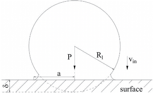
Johnson et al. (Citation1971) provide a static impact model in which elastic and adhesion forces are considered. The adhesion forces are confined to the area of the contact and are zero outside. Variables for the model are shown pictorially in . The particle radius is R1, the initial incident velocity and the contact radius is
. According to JKR theory, the normal pressure distribution over the contact area
, the relative approach of the two particle centroids
and contact force P1 may be expressed as
[1]
[1]
[2]
[2]
[3]
[3] where mechanical parameter E* is defined as
, R* is defined as
, for a sphere impacting with a flat surface (
) there is
, and the interface energy w is given by
.
,
and
are the Poisson ratio, Young's modulus and surface energy of the particle or the surface, respectively. With Equations (Equation2
[2]
[2] ) and (Equation3
[3]
[3] ), the
relationship can be established.
Using Equation (Equation1[1]
[1] ), the limiting contact pressure
is given by
[4]
[4] where
is the projected radius of elastic deformation at the end of the first stage.
Based on the JKR theory and Newton's second law, the motion equation of the particle in the first stage can be given by[5]
[5] where m is the mass of the particle, t is the contact time.
The nondimensional forms of Equations (Equation5[5]
[5] ) and (Equation2
[2]
[2] ) are
[6]
[6]
[7]
[7] whose expressions for the nondimensional contact radius
, force
, overlap
, limiting contact pressure
, and time
are
[8]
[8]
Differentiating Equation (Equation7[7]
[7] ), we get
[9]
[9]
By combining Equations (Equation6[6]
[6] ) and (Equation9
[9]
[9] ) and defining
as the initial conditions, Equation (Equation9
[9]
[9] ) can be integrated as
[10]
[10]
If is given,
can be obtained by solving Equation (Equation4
[4]
[4] ) through Newton's method. Hence, the normalized velocity at the end of the first stage
is given as
[11]
[11]
2.2. Adhesive elastic-plastic compression stage
During the second stage, in order to model the post-yield behavior, it is necessary to make some simplified assumptions. Assume that the contact yield stress is constant for a given impact velocity, the radius of contact area under plastic deformation is
and the force in annulus is a JKR pressure distribution. Then the normal force P2 is given by
[12]
[12]
Using the assumption of Bitter (Citation1963) that the area of the annulus of elastic deformation remains equal to the total contact area at yield, there is[13]
[13]
Hence, Equation (Equation12[12]
[12] ) can be simplified as
[14]
[14]
With Equation (Equation8[8]
[8] ), the nondimensional motion equation of the particle in the second stage can be obtained
[15]
[15]
Take as the boundary conditions, the
relationship can be given by
[16]
[16] in which
At the end of the second stage, the particle relative velocity is zero. Then, Equation (Equation16[16]
[16] ) = 0 can be solved numerically by using such as Newton's method. Hence, the normalized maximum contact radius
is obtained.
2.3. Adhesive elastic recovery stage
During the third stage, the behavior of the particle is equivalent to the unloading of an elastic sphere of radius , hence the contact curvature during unloading is
due to permanent deformation of the contact surfaces in the second stage. Assume that the contact force during this stage is provided by the JKR theory but with a changed radius of contact curvature and an unrecoverable relative displacement
. Hence the contact force and contact displacement can be given by
[17]
[17]
[18]
[18]
At the transition point from loading to unloading, there is , using Equations (Equation12
[12]
[12] ) and (Equation17
[17]
[17] ),
can be given by
[19]
[19]
Then with the maximum relative displacement ,
can be easily obtained by using Equation (Equation18
[18]
[18] ).
Because of the plastic deformation in the second stage, in Equation (Equation8
[8]
[8] ) has been replaced by
, then the normalized contact radius
, force
, overlap
, limiting contact pressure
and contact time
in the third stage can defined as
[20]
[20]
Then the equation of particle motion in the third stage can be written in a dimensionless form as[21]
[21]
Take as the boundary conditions, the
relationship can be given by
[22]
[22]
From JKR theory, the separation point of the particle is . Hence the normalized rebounding velocity
is
[23]
[23]
The restitution coefficient is defined as a ratio of the rebound velocity to the approach velocity, which is given by
[24]
[24]
3. Experimental validation of the model
The results of experiments for ammonium fluorescein particles impacting on silicon surface by Wall et al. (Citation1990) were used to validate the dynamic models. For 4.90 μm diameter particles, the velocity range was approximately 1∼100 m/s reported in their experiments. The material properties and parameters used in this study are shown in . Before applying the present model to actual calculations, it is necessary to give reason to adopt JKR theory for current problem. The criterion of the applicability is that the adhesion parameter defined by be larger than 5 (Johnson and Greenwood Citation1997). In current problem the minimum separation
and the adhesion work
, then the value of
is larger than 11 for 4.90μm diameter particles, which is substantially larger than the suggested minimum. Hence, the JKR theory serves as a good approximation in present work.
Table 1. Material properties.
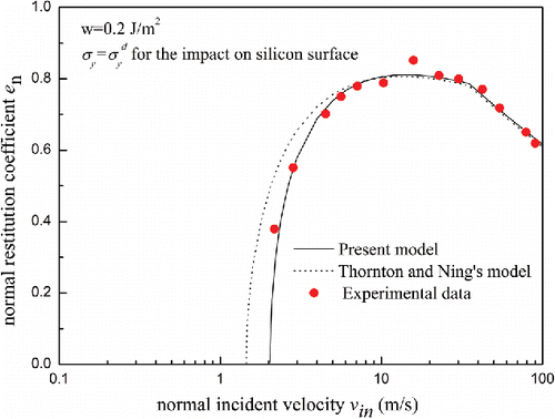
shows the measured and calculated restitution coefficient versus the normal incident velocity for ammonium fluorescein particles of 4.90 μm diameter impacting a silicon surface with the fitting parameters ,
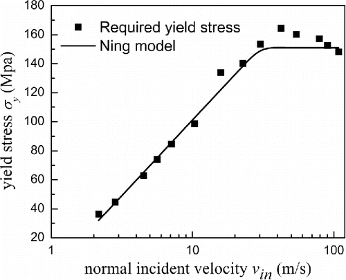
obtained by Wall et al. using the theories that neglected the surface energy during the loading stage. It can be seen that the simulated results both by the present model and Thornton and Ning's model significantly under-predict the restitution coefficient of the experimental results. What's more, Wall et al. instructed in their study that the value for the interface energy was higher than expected, and the surface energy for ammonium fluorescein is 0.01 J/m2 and for silicon the surface energy is 1.42 J/m2 (Gilman Citation1960) in . Hence, the work of adhesion used in present paper was 0.2 J/m2. As can be seen in , both simulated results do not agree well with the experimental results. For lower impact velocities, there is other energy loss except adhesive dissipation. For higher impact velocities, both the models predict redundant energy loss, which means the limited contact pressure needed in this velocity range is much more than 74 MPa. Therefore, further simulation should be performed to determine what values of
were required to fit the experimental data. Ignoring the possible decrease in yield stress due to shear heating at high velocities, the fitted values of yield stress (black square data) for 4.9 μm particles impacting silicon surface are illustrated in . In order to simplify the computational process, the black square data in can be approximately replaced by the solid line. According to the expression of dynamic yield stress developed by Ning (Citation1995), the dynamic yield stress is the function of impact velocity, which was written as
[25]
[25]
Figure 2. Comparison of present model and Thornton and Ning's model simulations for different surface energy with results of Wall et al. (Citation1990) for NH4Cl particles impacting a silicon surface.
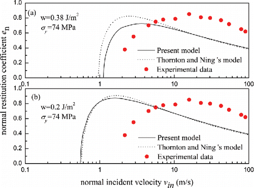
Figure 3. Effect of normal incident velocity on the yield stress required to fit the experimental data of Wall et al. (Citation1990) for silicon surface.
where A is a fitting coefficient.
Therefore, the solid line of the dynamic yield stress for silicon in can be defined as[26]
[26]
Both the present model and Thornton and Ning's model were then modified to incorporate the dynamic yield stress of Equation (Equation26[26]
[26] ) and the final simulated results are illustrated in , respectively. It can be seen that the present model shows good agreement with the experimental data over the full given velocity range, while Thornton and Ning's model does not match well with the experimental data when the impact velocity under 7 m/s.
4. Results and discussions
4.1. Effects of material parameters on 

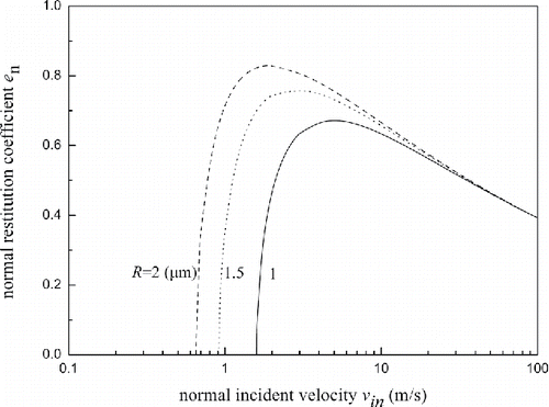
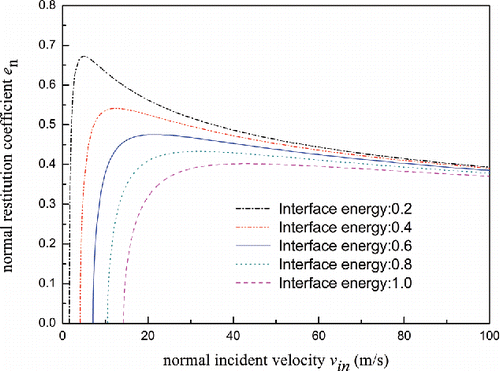
Simulations have been performed to examine the effects of material parameters such as particle radius, interface energy and yield stress on the restitution coefficient. To simplify the calculation, the static yield stresses are used in this section. illustrates the effect of particle diameter on the restitution coefficient obtained. The properties of both sphere and silicon wall are given in . It can be seen that the restitution coefficient increases at a decreasing rate to a maximum value and then decreases at an increasing rate. The maximum value of the restitution coefficient increases with increase in the particle diameter. However, the critical velocity increases with decrease in the particle diameter. For the impact velocities more than ten times the yield velocity (, is the relative impact velocity below which the interaction behavior is assumed to be elastic, in the case of a sphere impacting with a surface there is
), the restitution coefficient is not significantly affected by particle diameter. The reason is that plastic deformation becomes the dominant energy dissipation mechanism when the impact velocity is large enough, while for the finite-plastic-deformation impacts, the coefficient of restitution due to plastic deformation is velocity dependent and is not relevant to particle radius (Wu et al. Citation2003).
shows the effect of interface energy on the restitution coefficient. It can be seen that the restitution coefficient is sensitive to the value of interface energy at velocities below five times yield velocities but is not significantly affected by the interface energy for higher impact velocities. The reason is that adhesive effects dominate the energy loss for low velocity impact while it is almost negligible for sufficiently high velocity impact. It was found that the yield velocity is also affected by the interface energy.
Figure 6. Restitution coefficients versus normal incident velocity under different interface energy.
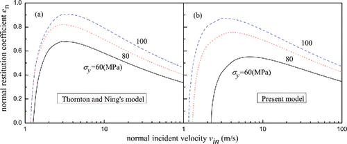
plots the effects of yield stress on the restitution coefficient predicted by present model and Thornton and Ning's model. Except for the value of the yield stress used, all the properties are given in for a NH4CL particle impacting a silicon surface. It can be seen that the normal restitution coefficients by both models increases with increasing yield stress. The reason is that the yield stress reflects the ability to resist material deformation, when the yield stress is lower, the plastic deformation is more likely to occur, which will result in more energy loss during an impact. The cases and
by present model show that the yield velocities (calculated from Equation (Equation11
[11]
[11] ) by Thornton and Ning [Citation1998]) are 2.33 m/s and 1.33 m/s, the critical capture velocities are 1.16 m/s and 1.29 m/s, the maximum restitution coefficients are about 0.87 and 0.76, respectively. When the yield stress is further reduced to 60 MPa, the yield velocity of 0.65 m/s is evidently less than the critical velocity 2.24 m/s and the maximum restitution coefficient reduces to 0.55. It can be seen that capture velocity is also affected by the yield stress, which is the same as Thornton and Ning (Citation1998). It also should be noted that when the impact velocity
, all the data follow approximately a power law relationship with an exponent of −1/4. However, the maximum restitution coefficients predicted by Thornton and Ning (Citation1998) for the three cases are 0.91, 0.82, and 0.68, which are all larger than present model. This may be due to the assumption that the work dissipated due to plastic deformation and work dissipated due to adhesive rupture are additive.
4.2. Influence of material parameters on 

The critical velocity is a criterion for determining whether particle bounce or adhere upon impact surface. The critical velocity is described by many researchers. The probability of a critical velocity was reported by Rogers and Reed (Citation1984), who termed it as adhesion velocity. Then according to JKR theory, Thornton and Ning (Citation1998) give the expression of adhesion velocity by neglecting energy losses due to elastic wave propagation and assuming that the only work dissipated during a collision is the work done in separating the surfaces:[27]
[27]
Wall et al. (Citation1990) determined critical velocities by extrapolating the energy balance equation to zero. While building on the work performed by Wall et al. (Citation1990), Dunn et al. (Brach and Dunn Citation1995; Cheng et al. Citation2002; Kim and Dunn Citation2008) used the force balance which was proposed by Hunt and Crossley (Citation1975) to derive the capture velocity considering the combined microsphere-target surface roughness :
[28]
[28] where
.
In present model, the critical velocity can be obtained with .
Hence, the critical velocities calculated by Equation (Equation27[27]
[27] ), present model and Thornton and Ning's model are presented in for the cases of different surfaces. The results predicted by present model shown in closely match to within approximately 20% those reported by Wall et al. (Citation1990) for the silicon, molybdenum, and tedlar surfaces, while the results predicted by Equation (Equation27
[27]
[27] ) and Thornton and Ning's model are significantly less than the critical velocities. The reason is that the Equation (Equation27
[27]
[27] ) only applies to adhesive-elastic spheres, during rebound the work done
by adhesion fracture force is dissipated. However, when the yield stress is sufficiently low,
is part of the energy that is dissipated during the rebound and inelastic strains in the microsphere and surface account for the remainder of the energy loss if neglect energy losses due to elastic wave propagation and vibrations.
Figure 8. Variation of critical velocity with particle diameter for different surfaces. The yield stress corresponding to the critical velocity for silicon and molybdenum surface are 32 MPa, while for tedlar surface is 36 Mpa.
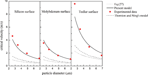
As can be seen from Equations (Equation27[27]
[27] ) and (Equation28
[28]
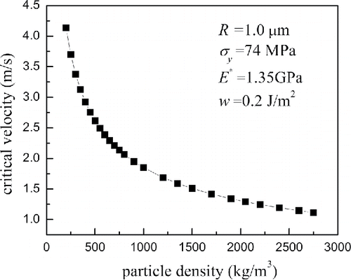
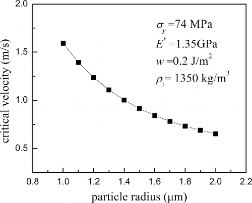
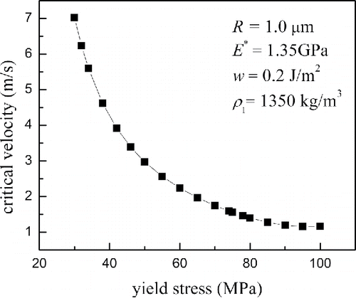
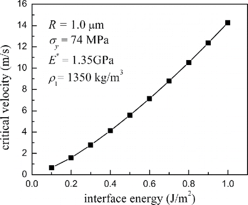
[28] ), and the description in Section 4.1, the critical velocity is the function of particle diameter and properties of impact subjects. In order to obtain the simplified empirical critical velocity expression, the effects of particle density
, particle radius
, yield stress corresponding to the critical velocity
, interface energy
, mechanical constant
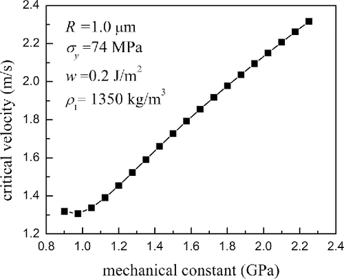
on critical velocities predicted by present model are plotted in . It was found that the critical velocity decreases with increase in the particle density, particle radius and yield stress, but increases with increase in the interface energy and mechanical constant. For the data in , the appropriate fitted expression of critical capture velocity obtained through the algorithm of universal global optimization can be written as
[29]
[29] with a correlation coefficient value of 0.9998 for 90 samples.
Equation (Equation29[29]
[29] ) indicates that the critical capture velocity is obtained when the total initial kinetic energy happens to be dissipated by both the adhesion energy losses and material irreversible deformation.
4.3. Relationship of contact force and displacement
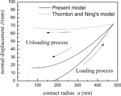
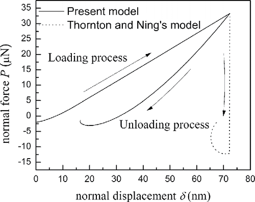
With and
relationships, the
relationship can be established implicitly. A typical case with 5 m/s for a 4.9 μm ammonium fluorescein particle impacting with the silicon surface was studied in this section. and show the comparison of the normal displacement-contact radius curves and normal force-displacement curves for present model and Thornton and Ning's model of the typical case, respectively. Both the models show that the impact starts from zero displacement, but with 177.4 nm contact radius. At the initial stage of the loading process, the total force is attractive. During the loading process, the normal displacement increases with the increase of contact radius and the total force also increases, when the normal displacement reaches 14.1 nm, the total force increases with the increase of normal displacement linearly. The maximum contact radius is 478.6 nm, the maximum displacement is 72.4 nm and the maximum force is 33.3 μN. The opposite phenomenon is observed during the unloading process. During the unloading, the total force is repulsive, but is attractive force at the ending stage. The differences between the two models are mainly reflected by unloading process. The reason is that the expression of
is different. The contact radius of the snap-off point is 70.4 nm.
4.4. Nonlinear dynamics of a particle-surface impact
The impact dynamics is investigated in terms of the evolution of force, particle displacement and velocity for two typical cases with different impact velocities. The case with impact velocity slightly above the critical value is mainly affected by the adhesive dissipation, while the one with high velocity
is primarily affected by plastic deformation. In the case studies, a 4.9 μm ammonium fluorescein particle impacts with the silicon surface, with the critical velocity equal to 1.96 m/s (Wall et al. (Citation1990). The dynamic yield stress used in the computation is shown in Equation (Equation26
[26]
[26] ). The critical velocity predicted by present model is approximately 2.04 m/s. The lower impact velocity is set to 2.0442 m/s while the high one is 50 m/s. Evolution of normal displacement, particle velocity and contact force during particle-surface impacts are shown in and , respectively. It should be noted that the normal displacement in the figures refers to total deformation, which includes both elastic deformation and plastic deformation.
Figure 16. Evolution of normal displacement, velocity and normal force during an impact with silicon surface of a particle with 4.90 μm diameter and impact velocity of 2.0442 m/s.

Figure 17. Evolution of normal displacement, velocity and normal force during an impact with silicon surface of a particle with 4.90 μm diameter and impact velocity of 50 m/s.

As for the impact with velocity of 2.0442 m/s, shown in , the impact starts from zero normal displacement. At the initial stage of the loading, the total force is attractive and thus the particle is accelerated. The particle later starts to decelerate when the total contact force increases to positive. When the contact force reaches its maximum 8.36 μN, the velocity becomes zero and the loading process ends with a plastic deformation of 32.7 nm. During the loading process, the yield velocity of 0.11 m/s is less than the sticking velocity of 0.56 m/s, which results in plastic deformation from the initial stage of the loading. During the unloading, the effective particle radius is 4.42 μm due to the plastic deformation in the loading process, the particle is first accelerated as the stored strain energy releases, but is again decelerated at the ending stage because of the attractive force. The normal displacement of the snap-off point is 25.8 nm and the rebound velocity of the particle is 0.02 m/s. Hence, the normal restitution coefficient is 0.01. It is also found that the loading time and the unloading time are both 40ns.
As for the impact with high velocity of 50 m/s, shown in , the particle motion appears to be simple. As the initial kinetic energy is big enough, the particle is almost decelerated at the initial stage of loading process, while during the unloading, the particle accelerating and the stored energy releases until it is separated from the surface. At the end of the unloading process, the adhesive force on the particle motion is not obvious and the rebound velocity is 36.3 m/s. Thus, for this case the value of restitution coefficient is 0.73. It is also found that the loading time is 13.5 ns and the unloading time is 11.9ns. The total contact time is much less than the case of 2.0442 m/s.
5. Conclusions
A dynamic elastic-perfectly plastic adhesive impact model was developed to predict the stick/bounce behavior for a normal particle-surface collision. The theoretical model is obtained by extending the JKR theory with plastic deformation and incorporating the Newtonian equation. The dynamic model were validated by comparison with the data in literature.
The model is capable of predicting the particle behavior during the collision process, and for lower velocities, the effect of adhesion is more obvious. The effects of interface energy and yield stress on particle rebounding properties are also investigated. It was found that an increase in interface energy leads to a decrease in the yield velocity.
A new expression for the normal capture velocity has been obtained, which can be a criterion to determine the fate of the particles normally impacting on the surface.
Additional information
Funding
References
- Antonyuk, S., Khanal, M., Tomas, J., Heinrich, S., and Mörl, L. (2006). Impact Breakage of Spherical Granules: Experimental Study and DEM Simulation. Chem. Eng. Process.: Process Intensification, 45:838–856.
- Bitter, J. G. A. (1963). A Study of Erosion Phenomena Part I. Wear, 6:5–21.
- Brach, R. M. and Dunn, P. F. (1992). A Mathematical Model of the Impact and Adhesion of Microsphers. Aerosol Sci. Technol., 16:51–64.
- Brach, R. M. and Dunn, P. F. (1995). Macrodynamics of Microparticles. Aerosol Sci. Technol., 23:51–71.
- Cheng, W., Brach, R., and Dunn, P. (2002). Three-dimensional Modeling of Microsphere Contact/Impact with Smooth, Flat Surfaces. Aerosol Sci. Technol., 36:1045–1060.
- Derjaguin, B. V., Muller, V. M., and Toporov, Y. P. (1975). Effect of Contact Deformations on the Adhesion of Particles. J. Colloid Interface Sci., 53:314–326.
- Gilman, J. J. (1960). Direct Measurements of the Surface Energies of Crystals. J. Appl. Phys., 31:2208–2218.
- Hassanpour, A., Antony, S. J., and Ghadiri, M. (2007). Effect of Size Ratio on the Behaviour of Agglomerates Embedded in a Bed of Particles Subjected to Shearing: DEM Analysis. Chem. Eng. Sci., 62:935–942.
- Hertz, H. (1896). Miscellaneous Papers. Macmillan, London.
- Hunt, K. H. and Crossley, F. R. E. (1975). Coefficient of Restitution Interpreted as Damping in Vibroimpact. J. Appl. Mech., 42:440–445.
- Jackson, R. L., Green, I., and Dan, B. M. (2010). Predicting the Coefficient of Restitution of Impacting Elastic-perfectly Plastic Spheres. Nonlinear Dynam., 60:217–229.
- Johnson, K., Kendall, K., and Roberts, A. (1971). Surface Energy and the Contact of Elastic Solids, in Proceedings of the Royal Society of London A: Mathematical, Physical and Engineering Sciences, The Royal Society, 301–313.
- Johnson, K. L. and Greenwood, J. A. (1997). An Adhesion Map for the Contact of Elastic Spheres. J. Colloid Interface Sci., 192:326.
- Kim, O. V. and Dunn, P. F. (2008). Direct Visualization and Model Validation of Microsphere Impact and Surface Capture. J. Aerosol Sci., 39:373–375.
- Liu, G., Li, S., and Yao, Q. (2011). A JKR-based Dynamic Model for the Impact of Micro-particle with a Flat Surface. Powder Technol., 207:215–223.
- Losurdo, M., Spliethoff, H., and Kiel, J. (2012). Ash Deposition Modeling Using a Visco-elastic Approach. Fuel, 102:145–155.
- Ning, Z. (1995). Elasto-plastic Impact of Fine Particles and Fragmentation of Small Agglomerates. Aston University, Aston, UK.
- Pasha, M., Dogbe, S., Hare, C., Hassanpour, A., and Ghadiri, M. (2014). A Linear Model of Elasto-plastic and Adhesive Contact Deformation. Granular Matter, 16:151–162.
- Rathbone, D., Marigo, M., Dini, D., and Wachem, B. V. (2015). An Accurate Force–Displacement Law for the Modelling of Elastic–plastic Contacts in Discrete Element Simulations. Powder Technol., 282:2–9.
- Rogers, L.N. and Reed, J. (1984). The Adhesion of Particles Undergoing an Elastic-Plastic Impact with a Surface. J. Phys. D: Appl. Phys., 17:677–689.
- Tabor, D. (1948). A Simple Theory of Static and Dynamic Hardness. Proceedings of the Royal Society A 192:247–274.
- Tabor, D. (1977). Surface Forces and Surface Interactions. J. Colloid Interface Sci., 58:2–13.
- Thakur, S. C., Morrissey, J. P., Sun, J., Chen, J. F., and Jin, Y. O. (2014). Micromechanical Analysis of Cohesive Granular Materials using the Discrete Element Method with an Adhesive Elasto-Plastic Contact Model. Granular Matter, 16:383–400.
- Thornton, C. and Ning, Z. (1998). A Theoretical Model for the Stick/bounce Behaviour of Adhesive, Elastic-plastic Spheres. Powder Technol., 99:154–162.
- Thornton, C., Cummins, S. J., and Cleary, P. W. (2017). On Elastic-plastic Normal Contact Force Models, with and without Adhesion. Powder Technol., 315:339–346.
- Wall, S., John, W., Wang, H.-C., and Goren, S. L. (1990). Measurements of Kinetic Energy Loss for Particles Impacting Surfaces. Aerosol Sci. Technol., 12:926–946.
- Wu, C. Y., Li, L. Y., and Thornton, C. (2003). Rebound Behaviour of Spheres for Plastic Impacts. Int. J. Impact Eng., 28:929–946.
- Xie, J., Dong, M., and Li, S. (2016). Dynamic Impact Model of Plastic Deformation between Micro-particles and Flat Surfaces without Adhesion. Aerosol Sci. Technol., 50:321–330.

