ABSTRACT
The accurate representation of aerosols in climate models requires direct ambient measurement of the size- and composition-dependent particle production fluxes. Here, we present the design, testing, and analysis of data collected through the first instrument capable of measuring hygroscopicity-based, size-resolved particle fluxes using a continuous-flow Hygroscopicity-Resolved Relaxed Eddy Accumulation (Hy-Res REA) technique. The Hy-Res REA system used in this study includes a 3D sonic anemometer, two fast-response solenoid valves, two condensation particle counters, a scanning mobility particle sizer, and a hygroscopicity tandem differential mobility analyzer. The different components of the instrument were tested inside the US Environmental Protection Agency's Aerosol Test Facility for sodium chloride and ammonium sulfate particle fluxes. The new REA system design does not require particle accumulation, and therefore avoids the diffusional wall losses associated with long residence times of particles inside the air collectors of traditional REA devices. A linear relationship was found between the sodium chloride particle fluxes measured by eddy covariance and REA techniques. The particle detection limit of the Hy-Res REA flux system is estimated to be ∼3 × 10⁵ m−2 s−1. The estimated sodium chloride particle classification limit, for the mixture of sodium chloride and ammonium sulfate particles of comparable concentrations, is ∼6 × 10⁶ m−2 s−1.
Copyright © 2018 American Association for Aerosol Research
EDITOR:
1. Introduction
1.1. Aerosol flux measurement techniques
Aerosols play an important role in controlling the Earth's radiation balance, cloud formation, cloud microphysical properties, biogeochemical cycling of nutrients, and tropospheric chemistry, and have been increasingly recognized for their adverse effects on air quality and human health. Aerosols arise from both natural sources and anthropogenic activities; therefore, to characterize relevant environmental effects, it becomes increasingly important to accurately quantify both number and mass concentrations of aerosols of different origin. Moreover, the characterization of both emission and deposition fluxes of aerosols is important for understanding the life cycle of aerosols and their potential influence on Earth's energy balance.
Recent studies have shown that accurate representation of the size distribution, number concentration, and chemical composition of natural background aerosols is critical for improved assessment of anthropogenic aerosol direct and indirect radiative forcing (Carslaw et al. Citation2013; Gantt et al. Citation2012; Wang and Penner Citation2009; Hoose et al. Citation2009; Lohmann et al. Citation2000). Large uncertainties attributed to how natural aerosols are represented in climate models has sparked renewed interest in improving the quantification of number, size distribution, chemical composition, and hygroscopic properties of aerosol within the marine boundary layer (MBL). Currently, the production, abundance, and mixing state of sea spray aerosol are not well constrained (Meskhidze et al. Citation2013). Global models commonly estimate the production of sea spray aerosol using wind speed-dependent flux parameterizations, which are often based on whitecap methods (de Leeuw et al. Citation2011), or more recent, Reynolds number-based sea spray aerosol emission parameterizations (Ovadnevaite et al. Citation2014). Today, more than an order‐of-magnitude uncertainty remains in the size‐dependent sea spray aerosol production flux formulations (de Leeuw et al. Citation2011). To constrain the representation of sea spray aerosol emissions in models, the effective sea spray production flux (defined as the flux of particles that attain a certain height, typically 10 m, de Leeuw et al. Citation2011) has been inferred in the lowest portion of the MBL using several micrometeorological techniques (Lewis and Schwartz Citation2004 and references therein; Norris et al. Citation2012). However, past studies looked at size-segregated aerosol fluxes over the ocean, without exploring their compositional dependence. In light of recent findings that show that sea spray particles could make up small fraction of aerosol number in the remote MBL (Royalty et al. Citation2017; Quinn et al. Citation2017), it becomes increasingly important to make direct ambient measurements of the size- and composition-dependent production flux of primary sea spray particles.
The majority of studies that measured size-resolved turbulent fluxes over different surfaces used the eddy covariance (EC) technique. In the EC technique, the turbulent flux (FEC) is derived as the covariance of instantaneous fluctuations in vertical wind speed (w') and particle concentration (c') from their respective mean values, i.e., . Typical aerosol-based EC systems consist of a sonic anemometer (for measuring three-dimensional wind) coupled with either condensation particle counters (CPCs), for measurement of total particle flux (Buzorius et al. Citation1998; Pryor et al. Citation2007), optical particle counters (OPC) for size resolved aerosol flux measurements of accumulation mode aerosol (Gallagher et al. Citation1997; Ahlm et al. Citation2010), or aerosol mass spectrometer (AMS) for chemically speciated aerosol flux measurements (Gordon et al. Citation2011). The EC systems have also combined sonic anemometers with instruments in which particles are segregated into several size bins using a compact lightweight aerosol spectrometer (Norris et al. Citation2012) or a passive cavity aerosol spectrometer probe with a heated inlet (de Leeuw et al. Citation2007). Although the EC flux measuring technique is a direct micrometeorological method of measuring vertical fluxes, it requires fast-response (typically 10 Hz) sensors, which often limit its application.
Lately, the relaxed eddy accumulation (REA) technique (Businger and Oncley Citation1990) gained popularity as an alternative to the EC technique for measuring atmospheric constituents. As the changes in the concentration for atmospheric constituents are strongly driven by 3D air movements (with the so-called eddies or turbulent whirls), with REA, updrafts and downdrafts are sorted into different collection reservoirs over an integration period sufficient to sample a representative range of eddy sizes. Based on the stability of the target analyte(s) in the reservoirs (e.g., level of reactivity or wall losses), the analyte(s) can either be analyzed on-site or in the laboratory. Overall, the efficacy of the REA method has been demonstrated through successful measurements of CO2 and water vapor fluxes (Pattey et al. Citation1993; Katul et al. Citation1996) as well as flux measurements of short-lived trace gases such as biogenic volatile organic compounds (Bowling et al. Citation1999; Arnts et al. Citation2013; Gallagher et al. Citation2000; Guenther et al. Citation1996; Velentini et al. Citation1997; Hornsby et al. Citation2009), nitrous oxide (Beverland et al. Citation1996), nitrous acid (Ren et al. Citation2011), and ammonia (Zhu et al. Citation2000). However, due to the complex nature of atmospheric particles, only a few attempts to measure atmospheric particle fluxes using the REA method have been reported. The REA total (or sub-micron) aerosol number fluxes were measured by Schery et al. (Citation1998) and Held et al. (Citation2008), while the REA size-resolved aerosol flux measurements via differential mobility particle sizer (DMPS) were carried out by Gaman et al. (Citation2004) and Grönholm et al. (Citation2007).
1.2. REA theory
The REA theory states that the vertical flux (FREA) can be determined by the product of the difference between the average concentration of species sampled during updrafts () and during downdrafts (), the standard deviation of the vertical wind velocity (), and an empirical dimensionless coefficient (
):
[1]
Following (Businger and Oncley Citation1990), can be expressed as:
[2] where
is the so-called deadband, a threshold magnitude of the velocity for up and down sampling (Pattey et al. Citation1993) and
is a theoretical value if the joint probability distribution (jpd) between w' and c' is Gaussian (Wyngaard and Moeng Citation1992; Baker et al. Citation1992). In practice, a wide range of
values have been reported. Numerical simulations of Wyngaard and Zhang (Citation1985) show
0.6 for the bottom-up field (that is due to the surface flux) when the jpd for w' and c' is Gaussian. Their study shows
0.47 for the top-down field (that is due to entrainment in the absence of a surface flux) when the jpd for w' and c' is non-Gaussian (Wyngaard and Moeng Citation1992). Experimental measurements reported a range (from 0.62 to 0.51) in the
values for different scalars (i.e., temperature, water vapor, ozone, carbon dioxide, and particle concentrations) largely associated with non-Gaussian form of the jpd between w' and c' (Katul et al. Citation1996 and references therein; Pattey et al. Citation1993; Gao Citation1995; Held et al. Citation2008). Introduction of the deadband (usually between 0 and
) can further widen the range (from 0.6 to 0.3) in the
values (Held et al. Citation2008 and references therein). Deadbands are often used in practice because they decrease the frequency of valve switching, increase the scalar concentration difference between the two reservoirs, and reduce errors due to uncertainties in the determination of updraft and downdraft scalar concentrations (Held et al. Citation2008).
Due to such variation in the experimentally determined coefficient,
is often determined from the regression between the measured covariance,
, and
for a given averaging period (Pattey et al. Citation1993; Oncley et al. Citation1993; Gaman et al. Citation2004; Held et al. Citation2008):
In general, the vertical wind speed component can be easily measured using commercially available sonic anemometers; therefore, the determination of the concentration differential (i.e., ) through differential sampling of updrafts and downdrafts is fairly straightforward. Nonetheless, applying the REA technique for measuring aerosol fluxes poses several challenges. First, the sorting of updraft and downdraft samples into their respective reservoirs should be performed without cross-contamination from the opposite direction. This issue can be addressed by using the minimum length of tubing between the inlet and the solenoid valve. Second, the sorting of updraft and downdraft samples should be performed using fast response (with the response time of few tens of milliseconds) solenoid valves that do not emit particles upon switching. The valves should be carefully characterized for size-resolved particle losses. Third, all the measurements should be done at a constant flow rate. Even minor fluctuations in the flow rate may lead to considerable concentration measurement errors by aerosol particle counters. Fourth, the sorting of updraft and downdraft samples into their respective reservoirs should be performed with the attempt to minimize the diffusional wall losses and coagulation in the reservoirs during the particle accumulation.
This article presents the design, testing, and validation of a novel REA system for measuring turbulent fluxes of size- and composition-dependent production flux of sodium chloride (NaCl) and ammonium sulfate (AS) particles. The continuous flow Hygroscopicity-Resolved Relaxed Eddy Accumulation (Hy-Res REA) system is designed to measure aerosol turbulent fluxes by separating ambient particles based on their ability to take up water, i.e., hygroscopicity. Efficacy for the continuous flow Hy-RES REA system was tested using NaCl, as its hygroscopicity is uniquely large. Traditional REA systems act as air collector devices; however, to avoid the diffusional wall losses associated with long residence times of particles in the sampling system, we propose a new REA system design that measures continuously and does not require particle accumulation. The system includes a 3-D sonic anemometer, two fast-response solenoid valves, two CPCs, a scanning mobility particle sizer (SMPS), and a hygroscopicity tandem differential mobility analyzer (HTDMA). System performance is evaluated by measuring turbulent fluxes of artificially generated particles inside a wind tunnel.
2. Experiment design and techniques
2.1. Wind tunnel
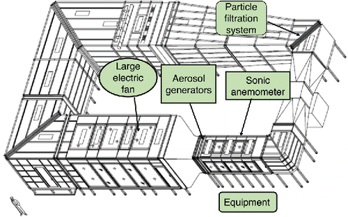
The operation of the continuous flow Hy-Res REA system was tested inside the U.S. EPA's Aerosol Test Facility (ATF) located in Research Triangle Park, North Carolina. Measurements were obtained between 15 March and 28 April 2017. shows a schematic diagram of the wind tunnel. At the location of the instruments, the wind tunnel had a square shape with dimensions of 1.5 m × 1.5 m. Turbulence was generated inside the tunnel with a large electric fan (Triangle Engineering of Arkansas, Inc., Jacksonville, AR, USA.) which was placed in the main section of the tunnel (∼5 m upwind from the particle generators) and large wooden blocks placed downwind from the fan. The mean wind speed inside the tunnel was maintained at 3 m s−1. An ultrasonic anemometer (model 81000, RM Young, Traverse City, MU, USA) measured the 3-D wind speed and direction at the sample inlet. The anemometer was mounted at ∼40 cm above the tunnel floor at the center of the equipment section (shown in ). Throughout the experiment, the location of the sonic anemometer and the sample inlet varied from 1 m to 3.5 m downstream of the aerosol generators. The wind speed and direction data were acquired at 10 Hz frequency. The wind tunnel included a HEPA filtration system which reduced the background total particle concentration to <2 cm−3 and 144 nm-sized (in diameter) particle concentration to <0.1 cm−3.
2.2. Particle generation
Sodium chloride particles were generated by bubble bursting inside the wind tunnel using two 40 L aquariums. Each aquarium was filled with tap water and ∼2.8 kg of Morton coarse salt (NaCl with small amounts of anticaking agent – hydrous form of sodium ferrocyanide, ) purchased in a grocery store. Every 2 days, ∼1 L water and ∼100 g of salt was added to the aquariums. Each aquarium had a dedicated pump, and air was bubbled through twelve (six in parallel for each aquarium), fine-porosity wooden frits, positioned over a depth range ∼10 cm below the air–water interface. It is well known that factors such as water temperature, salinity (Mårtensson et al. Citation2003; Lewis and Schwartz Citation2004), bubble generation techniques (Stokes et al. Citation2013), and the purity of the solution (Modini et al. Citation2013) are likely to affect the nascent NaCl particle production. However, over 15 min of the flux averaging time, the changes to the system were minor, and, therefore, had no measureable effect on the outcome of the study. Salt purity and water purity (tap water) had only a weak influence on the aerosol properties. Particle size distributions (PSDs) inside the wind tunnel were determined by using the SMPS method (Wang and Flagan Citation1990). The SMPS consisted of TSI 3081 long column mobility analyzer (TSI Inc., Shoreview, MN, USA) that was operated at a 5:1 sheath to sample flow ratio. Detailed operating procedures are described further below.
Ammonium sulfate particles were generated inside the wind tunnel by using a collision-type atomizer (TSI Inc. 3076). The atomizer was located outside the tunnel. Atomized particles were fed inside the tunnel using a combination of ¼ stainless steel and electrically conductive silicone tubing. A particle release port for the AS was constructed from 30 cm copper tubing which had five small holes equidistantly drilled at 5 cm intervals. The particle release port (the line source) was placed on top of the NaCl particle generators, perpendicular to the flow inside the tunnel. This allowed for generation of externally mixed aerosol composed of a mix of NaCl and AS particles.
2.3. Size-selected NaCl particle flux measuring setups
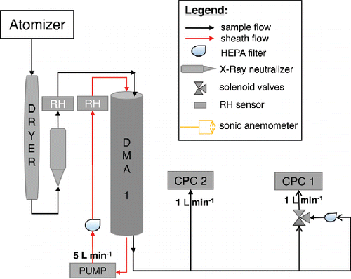
The instrument setup in shows four different operation modes. Mode 1 shown in illustrates the total NaCl particle EC flux measurement mode. In this mode, the covariance of total particle concentration measured by a condensation particle counter (CPC-1, TSI Inc. 3772) and fluctuations in wind speed are measured. Particle concentrations were logged at 10 Hz frequency using the digital pulse output from CPC-1. The total length of tubing from the inlet to the CPC-1 was ∼6.4 m. All lines consisted of a combination of ¼ inch stainless steel and conductive silicone tubing. The inlet was mounted at the sonic anemometer centerline, 5 cm behind the transducer. Such placement was chosen to minimize the distance between the sonic anemometer and the inlet, while still avoiding the flow distortion due to the presence of the tubing. The power spectrum of the turbulence (see Section 3.6) shows that most of the turbulent energy was contained between the frequencies of 0.2 and 4 Hz, i.e., in the eddy sizes of 1.5 m to 7.5 cm. Therefore, the distance between the sonic anemometer and the inlet is not expected to have a considerable effect on the flux measurements. The airflow in the main sampling line was maintained at 19.6 L min−1 to insure turbulent flow and minimize the diffusive smearing of eddies. The calculated Reynolds number for the sample line was 3080 and was greater than the critical Reynolds number of 2300 for transition to turbulent flow (Ito et al. Citation1971). The flow was split between CPC-1 (1.0 L min−1) and a vacuum pump (GAST DOA-P701-AA) connected to a critical orifice (18.6 L min−1). The line length between CPC-1 and the split was ∼3.5 cm. The time lag between the inlet and detection by the CPC-1 was empirically derived by allowing CPC-1 to measure zero-particle air by placing a HEPA filter on the end of the sample line and then removing the filter. The time it took for CPC-1 to measure a non-zero particle concentration was defined as ‘lag time’ and was determined to be 1.2 s. This lag time was within 5% of the value derived by using a cross-correlation analysis (Stull Citation1988), in which the vertical velocity time series were shifted backward in time relative to the NaCl particle number concentration time series, for data collected in Mode 1. The shift associated with the largest correlation coefficient was applied to all covariance calculations including particle concentration from Mode 1. Data were collected and averaged over a 15-min interval. The rationale for the averaging time interval is described further below.
Figure 2. Schematic of the experimental setup of NaCl particle fluxes: (a) total particle EC flux mode, (b) total particle REA flux mode, (c) particle size selected (at 144 nm) REA flux mode, and (d) particle size selected (at 144 nm) hygroscopicity-resolved REA flux mode.
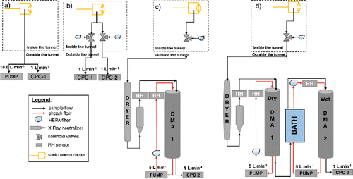
Mode 2 shown in is the total particle REA flux measurement mode. In this mode, the air from two separate inlets passed through two 3-way valves (IPS M443W1AFS-HT-132, International Polymer Solutions, Irvine, CA, USA) which allowed for separation of updrafts and downdrafts. The response time for the valves was 20–30 ms, about two orders of magnitude higher compared to the response time for CPC. Therefore, the delay due to the valve opening is not expected to introduce any discernible effect in the flux measurement. Updraft and downdraft air samples had their own separate inlet lines and solenoid valves. In the main sample lines, the CPCs were connected to the ‘common’ port of the respective solenoid valves. A HEPA filter was connected to both ‘normally open’ ports. CPC-1 typically measured updrafts while CPC-2 (TSI Inc. 3785) measured downdrafts. Updraft and downdraft concentrations were measured simultaneously. Both CPCs logged concentration at 10 Hz frequency. The averaging window for calculating fluxes was 15 min. The ambient concentrations measured by CPC-1 and CPC-2 were formally compared at the beginning and the end of the measurement period. The particle concentrations measured by both CPCs were within 5% of one another, so no data correction has been applied due to the difference in CPC readings.
The concentration outputs on the CPCs' LCD screens were visually monitored throughout the experimental period to ensure that drift did not occur. Conductive tubing (∼30 cm) ran from the ‘normally closed’ ports of the solenoid valves to the sonic anemometer (ambient sampling). The position of the solenoid valves was controlled by the magnitude and direction of as measured by the sonic anemometer. During instances of
, the solenoid valve corresponding to updrafts sampled ambient air (active) and the solenoid valve corresponding to downdrafts sampled filtered air (inactive). In contrast, when
, the solenoid valve corresponding to downdrafts sampled ambient air and the solenoid valve corresponding to updrafts sampled filtered air. Lastly, when
, both solenoid valves sampled filtered air. By logging the duration that each valve spent in sampling ambient versus sampling filtered air, the dilution factor (i.e., the contribution of the filtered air to time-averaged aerosol concentration) was calculated.
Mode 3 shown in corresponds to the particle size selected REA flux. The dry diameter (Ddry) = 144 nm was chosen to target the peak particle number concentration generated by the NaCl particle generators (see more below). Air was sampled through a single valve similar to Mode 2 at 1.0 L min−1. Instead of directly sampling with the CPC, sampled air was dried to relative humidity (RH) = 15% ± 2.0% using a Nafion membrane drier (Perma Pure PD-Series gas dryer). This RH is lower than the efflorescence relative humidity of 100 nm sized NaCl particles (44%) (Gao et al. Citation2007), so the particles were assumed to be dry. The RH of DMA-1 was actively monitored by an RH sensor (Rotronic hygroclip HC2) embedded in the sheath flow. More discussion about the sensor can be found in Section S1, “The RH sensor,” in the online supplementary information (SI). The air was passed through an X-Ray neutralizer (TSI Inc. Model 3088) to produce an equilibrium charge distribution. The aerosol was then size-selected by electric mobility with the differential mobility analyzer (DMA-1, TSI Inc. 3081) operating at a sheath-to-sample flow rate of 5.05:1. Upon transmitting through DMA-1, particle concentration was quantified using CPC-1. Since there was only one neutralizer in this study, the same valve was used to sample the updraft and downdraft air sequentially for a given location of the sonic anemometer and the inlet. As such, the following sequence was used when sampling in Mode 3 configuration: 144 nm REA-up and 144 nm REA-down for 15 min each. Sequential sampling is possible since the source particle flux and turbulence spectra do not vary with time during the experiment. To avoid mixing of the air inside the tubing between updraft and downdraft samples due to slow flow, 2-min purge time was introduced before starting data collection. Note that measurements of size-selected EC fluxes using DMA are not possible, as flows inside the DMA are laminar and not able to capture high frequency turbulent movement of particles that are necessary for resolving covariance of vertical velocity and particle concentration fluctuations.
Mode 4 shown in is the configuration used for measuring Hy-Res REA fluxes of NaCl and AS. Similar to Mode 3, sampled air was dried, charge neutralized and passed through DMA-1. DMA-1 size-selected Ddry = 144 nm (particles attributed to the diameter bounds of the DMA transfer function, i.e., 129–166 nm) while operating at a sheath to sample flow ratio of 15.9:2. The sample flow was then split so CPC-2 sampled the monodisperse particle concentration at 1 L min−1, while another 1 L min−1 passed through a Nafion submerged in temperature controlled water. Air passing through the submerged Nafion membrane then passed through a second DMA (DMA-2, TSI Inc. 3081). The sheath to sample flow for DMA-2 was 5:1. The HTDMA system RH was monitored at a 1 Hz frequency by one RH sensor within the sample and one RH sensor within the sheath flow of DMA-2. The RH inside DMA-2 was actively controlled by varying the dew point temperature of the sheath and sample flows. Outer column temperature was controlled by four thermoelectric cold plate heat exchangers (TE Technology, Inc. CP-031) which were mounted to the top and bottom of DMA-2. The four thermoelectric heat exchangers were set to match the temperature measured at the center of DMA-2. Column temperature was monitored with three thermistors mounted to the top, middle, and bottom of the outer DMA column. Lastly, DMA-2 was insulated with 0.5-inch neoprene to minimize rapid perturbations in ambient temperature. The standard deviation of the top, middle, and bottom temperatures were consistently ±0.01°C when evaluated over a 6 h measurement period. This type of HTDMA configuration was shown to produce stable RH measurements up to RH = 99% (Suda and Petters Citation2013; Dawson et al. Citation2016). The humidified DMA column led to hygroscopic growth of the dried monodisperse particles. The voltage of DMA-2 was set based on a target hygroscopic growth of the dry monodisperse aerosol (Ddry = 144 nm) as well as low frequency changes in the HTDMA system RH. Particle transfer through DMA-2 was measured by CPC-1 at 1 L min−1. To ensure DMA-1 and DMA-2 sized particles consistently, “dry-dry” scans were performed with the HTDMA system out at the beginning, middle, and end of the experiment period. Atomized AS was introduced into the HTDMA system. DMA-1 selected AS particles with 144 nm dry mobility diameter. The monodisperse aerosol manually bypassed the humidification system and entered DMA-2. By bypassing the humidification system, the RH in DMA-2 was RH < 30% (25 ± 5%). Instead of setting a voltage, DMA-2 scanned over a voltage range. The measured peak dry diameter in DMA-2 was within 2 nm of the nominal dry diameter of DMA-1. Lastly, the valve system for Mode 4 operated the same as Mode 3 such that the following sequence was used: 144 nm Hy-Res REA-up for 15-min and 144 nm Hy-Res REA-down for 15 min.
2.4. SMPS and HTDMA concentration corrections
Observed size-resolved concentrations during flux measurements for Modes 3 and 4 were corrected for charging efficiency, multiplied by a factor of two to account for the shape of the DMA transfer function, and normalized by the log10 ratio of the transfer function bounds (Petters et al. Citation2009). Since the same particle loss processes existed in DMA-1 while using DMA-1 in the HTDMA configuration, all reported HTDMA fluxes were corrected similarly to the size-resolved fluxes. In addition, reported HTDMA fluxes were divided by a factor of 0.7 (Section 4.2) which corresponded to the empirically-derived transfer efficiency of dry monodisperse aerosol from DMA-1 through DMA-2. Particle losses in the sampling line were calculated to be less than 15% for 34.7 nm < Ddry < 360 nm and less than 5% for Ddry= 144 nm (Kulkarni et al. Citation2011). More details about the particle losses inside the lines for different flow regimes can be found in the Section S2, “The particle losses,” in the SI.
3. Experimental methods and data analysis
3.1. The random valve test
Random valve tests (RVT) were performed to quantify bias associated with size dependent transmission of particles through the valves. During the RVT, the solenoid valves are triggered at random intervals and kept open for a known amount of time. Opening and closing is not related to any flux, and the expected concentration should correspond to the average time the valve was sampling. Deviations from the average are related to particle inertial and diffusional losses in the valves. As shown further below, the two valves of the same model demonstrated variable losses that may be associated with minute inconsistencies in the valve assembly. Therefore, it is crucial to calibrate each valve thoroughly and develop the valve transmission functions prior to usage. shows the configuration that was used for conducting RVTs. Atomized, dried, and charge neutralized AS particles were size-selected by DMA-1 to Ddry values corresponding to bin midpoint diameters ranging from 10 to 600 nm. The sample exiting DMA-1 was split between CPC-2 to measure total particle number concentration for the size-selected diameter particles and another sample line split, where both lines went to the valve. One sample line (after split) had a HEPA filter in series prior to connecting to the normally open port of the valve. The other line directly connected to the normally closed port of the valve. Lastly, CPC-1 connected to the common port of the valve to measure valve transmission as a function of Ddry. Having both the normally open and normally closed valve ports in parallel with the main sample line ensured a stable flow through DMA-1. The RVTs were performed separately for both 3-way solenoid valves. Software for RVTs generated a random number between 0 and 1 at a 10 Hz frequency. Thresholds were defined in the code such that the valve would activate (i.e., sample non-filtered air) if the random value exceeded the defined threshold. A given threshold was maintained for a 5-min interval which allowed for sufficient particle transmission statistics. Different thresholds were iterated through to account for biases associated with different valve clicking frequencies. Thresholds used during RVTs corresponded to the valves being in the open position for 10% (i.e., the random value > = 0 but 0.1), 20%, 30%, 40%, 60%, 80%, and 100% of the time. The valve opening and closings were recorded, and the fraction of time open during a given 5-min interval were within 2% of the assigned threshold. The ratio between the mean concentration of CPC-1 and CPC-2 was considered the transmission efficiency for a given size particle at a given clicking frequency. The transmission efficiencies for all tested sizes and frequencies were used to develop a valve transmission function described below.
3.2. The valve transmission function
The RVTs revealed that the 3-way solenoid valves had differential losses for different size particles. summarizes the data for the RTVs. The solid black line shows the transmission fraction that is expected due to the dilution of the particle concentration. In effect, recovered concentration should be proportional to the duration that a given valve is open (e.g., a valve open 30% of the time should have an observed 70% dilution effect on the mean concentration). In practice, biases such as diffusional losses or differential click response between opening and closing can lead to deviation from this theoretical line. Nonetheless, via RVTs, shows the actual transmission fraction for particle sizes from 17 to 144 nm. According to , the valve losses of particles were higher for smaller particle sizes. The losses of the particles with Ddry > 144 nm were minor (and comparable) within the valves and therefore are not shown. also shows that, due to extremely high losses, valves used in this study may not be suitable for measuring fluxes for nm sized particles. The data in were used to develop valve transmission functions. The apparent linearity of the data warranted the application of a best-fit linear loss model such that:
(4) where
is the fractional dilution factor for a given dry size particle
, valve
, and fraction of time open
,
is a loss coefficient which is dependent on both V and Ddry, and
is the size and valve dependent bias derived from the fitting function. Values for
and
are reported in Table S1 of the SI. These functions were used for correcting aerosol losses associated with the valve operation by dividing
and
by
.
Figure 4. Size selected valve transmission fractions due to air dilution and particle loss inside the 3-way solenoid (a) valve-1 and (b) valve-2.
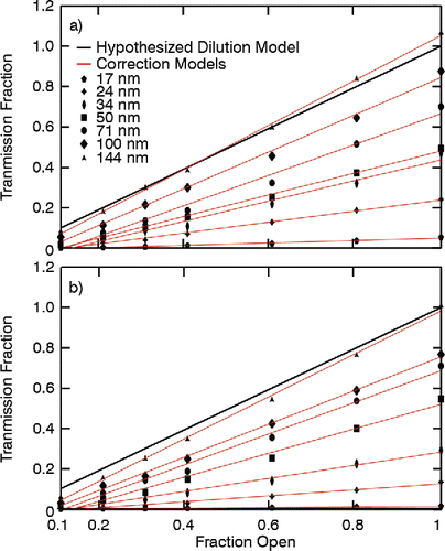
Overall, the RVT shows that all solenoid valves need to be carefully calibrated prior to application in aerosol REA measurement systems, as even small differences in the valve transmission could greatly affect both total and size-selected (sub-144 nm for the current valves) particle flux measurements.
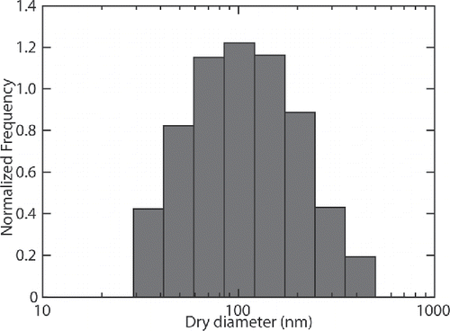
3.3. Application of valve calibration to NaCl particle size distribution
The NaCl size distribution was set to a fixed, geometrically spaced 12-bin grid. The geometric mean diameters for the individual bins were 12.0, 17.1, 24.3, 34.7, 49.6, 70.7, 100.9, 144.0, 205.5, 293.3, 418.6, and 597.3 nm. The NaCl particle size distribution inside the wind tunnel showed that particles with geometric mean dry diameters nm accounted for ∼ 2% of total particle number concentration. Therefore, only particles with
nm were used for the analyses. shows an example of particle size distribution with the valve transmission function correction shown in . In practice, valve corrections are always needed for the REA particle flux measurements, especially when two valves with dissimilar losses for different sized particles are used.
3.4. Time series of wind velocity and particle concentration
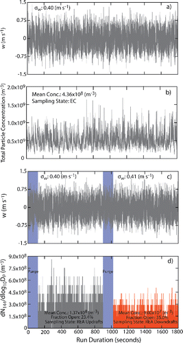
and b show a typical time series of observed vertical velocity and total particle number concentration for the instruments recording the 10 Hz data during Mode 1 (i.e., EC). Vertical velocity fluctuations were within ±0.75 m s−1, with an average = 0.40 m s−1. Sodium chloride particle number concentration did vary from 2 × 10⁸ to 1.5 × 10⁹ m−3 with a mean concentration of 4.36 × 10⁸ m−3. All data were despiked to remove occasional spurious outputs from instruments and corrected for the lag time. and d show a typical time series of observed vertical velocity and REA time series of particle number concentration during updrafts and downdrafts in Mode 2. The concentration data were corrected for the valve opening/closings in up, down, and deadband positions. shows that on average, mean concentration of NaCl particles in the updrafts is higher (1.37×10⁸ m−3) compared to the one in downdrafts (9.00×10⁷ m−3), contributing to the positive vertical turbulent flux. Note that while the location of the sonic anemometer and the inlets were the same for , the EC and REA flux measurements do not share the same vertical velocity timeseries as they were measured during back-to-back runs. Nevertheless, shows that the variability in
was within the uncertainty of the sonic anemometer (i.e., 0.05 m s−1)
3.5. Quadrant analysis
shows a 15-min two-dimensional frequency distribution of NaCl particle number concentration fluctuations normalized by 5-min running mean standard deviation of concentration () versus vertical wind fluctuations normalized by 5-min running mean standard deviation of vertical velocity (
) collected inside the ATF wind tunnel. Data points represent individual points collected at 10 Hz frequency. Positive values indicate the upward flux of NaCl aerosol. Periods with
and
(quadrant 1), and periods with
and
(quadrant 3) contribute to the upward NaCl particle flux in a positive way. This is because the particle source is located at the ground and the upward moving air generally contains higher concentration of NaCl and the downward moving air contains lower concentration of NaCl. This picture is consistent with the intuitive notion that NaCl particles move along the mean concentration gradient. However, also shows that some sample air falls into quadrants 2 and 4, which corresponds to updrafts of lower concentration parcels (
and ) and eddies with higher NaCl concentration moving downward (
and
), respectively. These points are associated with counter gradient flow and diminish the measured mixing ratio differences between updrafts and downdrafts (i.e., and
), contributing to a lowering of the turbulent flux of NaCl particles (Bowling et al. Citation1999).
Figure 7. A two-dimensional frequency distribution of NaCl particle number concentration fluctuations (c') versus vertical wind velocity (w') fluctuations averaged over 15-min period. Both quantities are normalized and nondimensionalized through dividing by their respective standard deviations. Vertical dashed lines show the REA sampling threshold of |w0| /σw = 0.8.
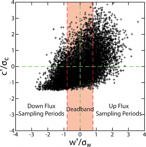
If no threshold is applied to a magnitude of the vertical velocity for up and down sampling, such REA sampling approach would analyze all updraft air (all points with in quadrants 1 and 4) and all downdrafts with (
, quadrants 2 and 3). The inclusion of air from the counter-gradient quadrants (2 and 4) limits the mixing ratio difference (
and the analytical capability of the instrument for measuring fluxes (Oncley et al. Citation1993; Bowling et al. Citation1999). To maximize signal (mixing ratio difference) to noise (measurement uncertainty) ratio, Oncley et al. (Citation1993) propose using the threshold velocity,
, to define a deadband where no sampling is performed. Assuming a normal probability distribution for the vertical velocity distribution, Oncley et al. (Citation1993) show that the concentration difference has a broad maximum near
. The dashed line in shows
, the value that was used in this study as it gave a good separation between updraft and downdraft concentrations. Using
in the wind tunnel lead to mean up, down, and deadband fractions of about 22%, 32%, and 46%, respectively. The differences between the fraction of times the valves were open for updraft and downdraft sampling indicates non-Gaussian probability density function (pdf) (the measured average skewness and kurtosis were 0.07 and 2.34, respectively) for the vertical velocity fluctuations.
3.6. Turbulent spectra inside the ATF
One-dimensional mean power density spectra of sonic temperature (T), horizontal (u), and vertical (w) wind velocities, and particle concentrations (c) are presented in . All spectra were calculated using the fast Fourier transformation technique over 15 min windows. The resulting power spectra were then normalized by dividing a given spectra by the integrated power spectra. In addition to the mean spectra, spectra representing 95% confidence intervals and the 5% to 95% quantile range are also presented in . shows flat spectra for T suggesting that the turbulence inside the ATF wind tunnel was largely shear driven. This result is supported by FLIR thermal images (not shown) that display uniform temperature distribution throughout the tunnel. The slope in the temperature spectra at low frequencies (Hz < 0.01) is indicative of changing conditions (heating/cooling) within the ATF building housing the wind tunnel.
Figure 8. Example power density spectra of (a) temperature, (b) horizontal velocity, (c) vertical velocity, and (d) NaCl particle concentration. Black lines correspond to mean spectra (n = 23), the dark gray shaded regions correspond to the respective 5th and 95th confidence intervals for the mean spectra, and the light gray shaded regions correspond with 5th and 95th quantiles for the mean spectra. The dashed (red) line shows −5/3 slope characteristic of turbulence spectra at higher frequencies.
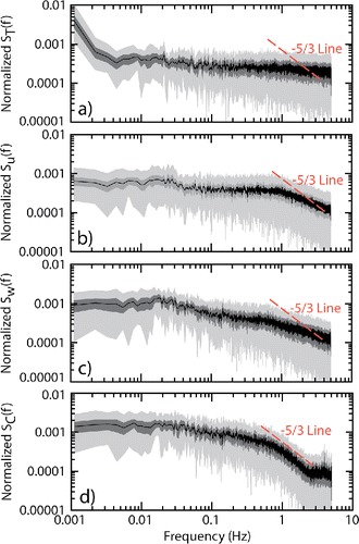
and show that in the inertial subrange (i.e., 1–10 Hz), the power-law part of the u and w spectra are flatter compared to the well-known −5/3 Kolmogorov scaling. Turbulent energy spectra with more or less approximate −5/3 power-law ranges have been found in many high Reynolds number fully developed turbulent flows. However, wind tunnel experiments have also shown the absence of such spectral signature for grid-generated, not-fully developed turbulence (Laizet et al. Citation2015). Moreover, Isaza et al. (Citation2014) showed that at turbulent flows, measured at certain distance away from their generation, there is no clear Kolmogorov signature whatsoever in the turbulent energy spectrum. Other reasons for the departure of w spectra from −5/3 slope characteristic of the inertial subrange could be the transducer shadow effect (Wyngaard and Zhang Citation1985), non-Gaussianity of the turbulence (Isaza et al. Citation2014), and the proximity to the wind tunnel floor (Hunt and Morrison Citation2000). It is outside the scope of the current paper to fully characterize the turbulent structure in the tunnel. As discussed in Section 4.1, the potential lack of fully-developed, homogeneous, and isotropic turbulence inside the tunnel may influence the derived value of .
The particle concentration spectra shown in reveals the well-defined −5/3 slope in the frequency range 0.5–2 Hz. However, also shows that spectral slopes flatten (the CPC white noise) close to 2.5 Hz raising the possibility of the turbulent flux losses at higher frequencies. Flux losses due to frequency response of the CPC were corrected using the approximation of Horst (Citation1997) (see below).
3.7. Flow dynamics and the averaging time
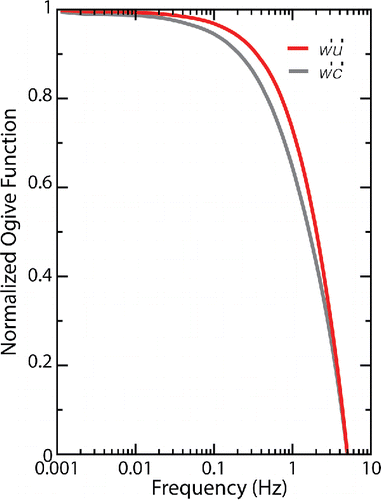
Typical averaging time for boundary-layer turbulent flux measurements is ∼30 min. In this study, the flux averaging time was adjusted to strike an appropriate balance between representative range of eddy sizes to turbulent flux contribution inside the tunnel, while minimizing possible low-frequency contributions from changing conditions inside the ATF wind tunnel (Sievers et al. Citation2015). shows cumulative cospectral energy functions (ogive curves, and
) calculated by cumulative summation of cospectral energy starting from the highest frequencies (Sievers et al. Citation2015):
(5) where
stands for the horizontal velocity or concentration fluctuation. The integral ranges from a higher frequency (highest frequency recorded) toward a lower frequency (frequency of interest). shows that below 0.01 Hz (100 s) both the
and
ogive functions converge to an asymptote, suggesting that 15 min (∼0.001 Hz) is a sufficient flux averaging time inside the wind tunnel.
3.8. Flux corrections
In general, ‘true’ particle flux may deviate from the turbulent flux measured using EC and REA methods due to departures of particle motion from the turbulent air motion. Processes such as Brownian diffusion, inertial relaxation, and gravitational settling can have sizable contribution to sub-micron sized particle fluxes under different environmental conditions (Feng Citation2008). Section S3, “Calculation of size-resolved particle velocities,” and Figure S2 in the SI show that for the conditions inside the wind tunnel, turbulent transport dominates the transfer of sub-micron particles and therefore the other terms can be ignored.
Since the flux setup was tested inside the wind tunnel, certain correction relevant for flux measurements in ambient conditions were not applied to the data. Humidity corrections (Webb et al. Citation1980) and the contamination of turbulence due to the motion of ships and buoys at sea (Edson et al. Citation1998) represent a major source of uncertainty in measurements of turbulence in the marine atmospheric boundary layer. Webb–Pearman–Leuning (WPL) corrections (Webb et al. Citation1980) are often performed to account the variation in particle concentrations due to vertical variations in air density (associated with temperature and humidity gradients). When making size-resolved particle number flux measurements, variations in RH may also cause changes in particle size due to absorption or loss of water. The average RH inside the wind tunnel was ∼50% with an undetectable gradient and in size-selected REA measurement configuration particles were dried to 15% prior to sizing. Therefore, humidity corrections were not applicable to the measured flux data. Section S4, “Flux corrections” in the SI discusses some details for humidity correction as it may be important for the field measurements. Section S5, “Diffusional losses and uncertainty estimates” in the SI discusses uncertainties in flux measurements that were evaluated for Modes 1 through 4. The fractional uncertainty values are summarized in Table S3.
Turbulent measurement corrections due to platform motion (i.e., instantaneous tilt of the anemometer due to the pitch, roll, and heading variations of the platform; angular velocities at the anemometer due to rotation of the platform about its local coordinate system axes; and translational velocities of the platform with respect to a fixed frame of reference) and the flow distortion by the vessel have been discussed elsewhere (Edson et al. Citation1998; Miller et al. Citation2008).
Finally, direct measurement of turbulent scalar fluxes may need to be corrected if the measuring sensor is too slow to correctly record the smaller wavelength eddies contributing to the flux. Correction for the attenuation of CPC-1 and CPC-2 response at frequencies above ∼2 Hz. Using the approximation of Horst (Citation1997), the ratio of measured to “true” flux (Fm/F) inside the wind tunnel can be given as Pryor et al. (Citation2007):(6) where the mean wind speed,
= 3 ms−1, the effective measurement height, z = 0.5 m, and the time constant of the sensor response,
0.3 s. Using these values, we estimate Fm/F = 0.51, i.e., ∼50% of flux loss due to frequency response of the instrument. This value is in a good agreement with 0.50 reported by Horst (Citation1997) for the neutral limit
and
= 1.8. The flux loss correction of 0.51 was applied to all EC fluxes.
4. Results and discussion
4.1. Estimation of 
Our first step in the flux calculation is the derivation of the parameter, an experimentally determined coefficient in EquationEquation (1
[1] ). The algorithms used in the REA flux calculations are based on the assumption of similarity of the turbulent exchange of scalar quantities (Kaimal et al. Citation1972). Therefore, estimates of
can be readily made with sensible heat flux (Businger and Oncley Citation1990; Baker et al. Citation1992; Gao Citation1995), vapor flux (Businger and Oncley Citation1990; Gao Citation1995; Katul et al. Citation1996), CO2 flux (Pattey et al. Citation1993; Sommar et al. Citation2013; Katul et al. Citation1996), or particle flux (Held et al. Citation2008; Gaman et al. Citation2004 as discussed above, in the surface layer,
values derived from experimental studies are generally lower than the ideal value of
, due to the non-Gaussian nature of turbulence and nonlinearity in the expected relation between w' and c' (Businger and Oncley Citation1990; Oncley et al. Citation1993; Gao Citation1995; Katul et al. Citation1996; Sommar et al. Citation2013). Furthermore, significant variation of as a function of atmospheric stability (Businger and Oncley Citation1990) and the deadband value (Pattey et al. Citation1993; Held et al. Citation2008) has been reported. In order to empirically determine
for the ATF wind tunnel during these experiments,
was treated as a proportionality constant as in EquationEquation (3
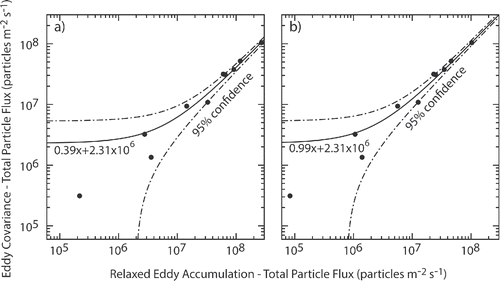
[3] ). Measurements of total particle EC flux (Mode 1) and total REA flux (Mode 2) were taken sequentially. shows a comparison of total particle fluxes using EC and REA methods. Each symbol represents 15-min averaged flux data collected by sequentially running the instruments in Modes 1 and 2. As conditions did not change significantly inside the tunnel, each pair of measurements was made by placing the sonic anemometer and the sample inlet at the different distances from the source. shows the linear relationship between the two methods of the particle flux measurements with the difference between the values attributed to the proportionality constant
. As such, the slope of the line was taken as . shows comparison of total particle fluxes using EC and REA methods after applying the
= 0.39 to the REA flux. This figure shows that the single value of
can be used for the majority of the flux measurements in the ATF wind tunnel and suggests consistent turbulent conditions as these measurements were taken over several days, collectively. The value of
derived in this study is comparable to the value of
0.4, reported over the 9 m high walnut orchard for the same deadband value (Held et al. Citation2008) and the value of
= 0.34 calculated using Equation (Equation2
[2] ) for
. Hereinafter = 0.39 is used for all calculations of particle fluxes using REA method.
4.2. Size-selected NaCl particle fluxes
shows REA flux of 144 nm sized NaCl particle plotted against EC flux of total NaCl particle number. Each symbol represents 15 min averaged flux data collected by sequentially running the instruments in Modes 1 and 3 (i.e., in EC and REA modes). As mentioned above, the measurements of size-selected EC fluxes were not feasible with the DMA-based system. The consequence of a DMA-based flux system is the necessity for correcting observed concentrations of and
in EquationEquation (1
[1] ) for the fractional transfer of a monodisperse aerosol through a DMA (TDMA), which is taken as the shape of the triangular DMA transfer function as well as the charging efficiency (Zeff) for the monodisperse aerosol through a neutralizer. Thus, for a DMA-based monodisperse aerosol flux (FREA,Ddry) measured via the valve system described above, the REA flux calculation in EquationEquation (1
[1] ) is modified as:
(7) where Df is the fractional dilution factor for a given dry size particle (see EquationEquation (4
(4) )). For positively charged Ddry = 144 nm size particles Zeff = 0.2158 (Wiedensohler Citation1988; TSI Incorporated Citation2009, Table B-1) and TDMA has a value of 0.5 (Knutson and Whitby Citation1975).
Figure 11. NaCl particle size selected (144 nm) REA flux plotted against EC flux of total NaCl particles.
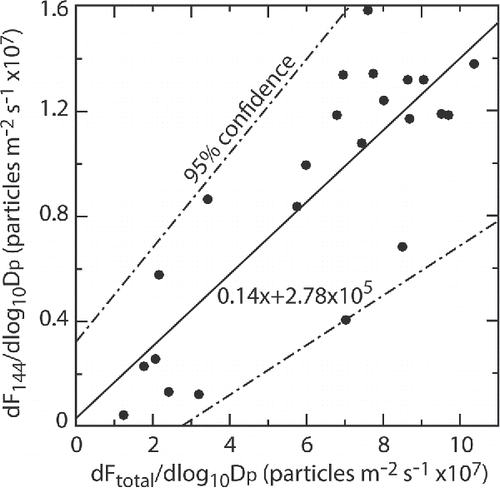
As expected, shows that particle flux values measured by the EC technique (registering all particles) are higher compared to 144 nm sized particles measured using the REA technique. The fractional contribution of the 144 nm particle REA flux to the total particle flux (the slope in ) is expected to be proportional to the relative contribution of the 144 nm particles to the total particles in the NaCl size distribution shown in . As such, the comparison of the slope in with the fractional contribution of 144 nm particles to total NaCl particle number can be used as a semi-independent assessment of the EC and 144 nm particle REA flux measurements. When accounting for the transfer function bounds, the fractional contribution of 144 nm particle to the total NaCl particle is estimated to be 12.9%. This value is within 8% of the slope in . This result suggests that (1) all the assumptions made for EC-REA flux comparison for the total particle fluxes can also be applied for the size selected particle fluxes and (2) conditions inside the wind tunnel were approximately invariant in time, so ‘‘single-valve’’ (as is required for Mode 3 and 4 due to a lack of instrumentation resources) fluxes measured in two 15-min sequential runs can be compared to each other.
4.3. Hygroscopicity-Resolved (Hy-Res) REA NaCl particle fluxes
shows Hy-Res REA fluxes for 144 nm sized particles plotted against REA fluxes of 144 nm sized particles. Since Mode 4 included CPC-1 and CPC2, size-resolved REA fluxes and Hy-Res fluxes were measured simultaneously. Black circles and black stars in correspond to fluxes measured for 144 nm sized NaCl and AS particles, respectively. This was achieved by setting the voltage for DMA-2 according to the hygroscopic growth parameter (κ) (Petters and Kreidenweis Citation2007) for the NaCl and AS solutions measured during the experiment. The values (κNaCl = 1.3 and κAS = 0.5) were derived via spray atomization of bulk solutions into the HTDMA system and operating DMA-2 as a scanning mobility particle sizer mode (Dawson et al. Citation2016) at RH ≅ 80%. The resulting humidified size distribution was fitted to find the mode diameter from which the κ values for the given bulk solution were determined. The κ values derived this way are consistent with those expected for NaCl and pure AS. Hy-Res versus size-resolved fluxes for both NaCl and AS shared the same slope which indicates the particle transfer in HTDMA system is not a function of particle composition when experimentally-derived κ values are used for setting the HTDMA voltage. Although the Hy-Res REA fluxes used tandem DMAs, the correction for Zeff in EquationEquation (7(7) ) was applied to account only for losses through DMA-1. Passing a monodisperse aerosol through DMA-2 alters the transfer function from the first DMA. To account for this, we have calculated the transfer efficiency for DMA-2 following Knutson and Whitby (Citation1975), assuming a 15.9:2 flow ratio for DMA-1 and a 5:1 flow ratio for DMA-2 for a Ddry = 144 nm. The theoretical value of 0.79 for the transfer efficiency of the monodisperse aerosol from DMA-1 through DMA-2 is slightly higher compared to empirically derived value of 0.67 (i.e., the slope for the Hy-Res REA fluxes of 144 nm sized particles plotted against REA fluxes of 144 nm sized particles). This correction to account for the transmission efficiency of DMA-2 has not been applied to the Hy-Res REA data in , so ‘true’ (NaCl and AS) and ‘contaminant’ (see discussion below) fluxes can be compared on the same figure (solid green line on shows 1:1 line). In practice, observed Hy-Res fluxes should be adjusted to account for the second DMA losses by dividing by the slope between Hy-Res and size-resolved fluxes.
Figure 12. Hygroscopicity-resolved REA fluxes of 144 nm sized particles plotted against REA fluxes of 144 nm sized particles.
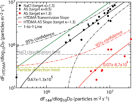
When attempting to measure low concentrations using HTDMA setup with relative short scans times, broadening the HTDMA transfer function can improve counting statistics (Royalty et al. Citation2017). However, wide transfer functions also introduce a possibility that species with a κ value different from that of the target κ can contaminate flux signal. In the case of sea-salt, Royalty et al. (Citation2017) show that partially to fully neutralized sulfate species are the most likely aerosol types to produce false signal when quantifying sodium-containing aerosol species in the MBL with an HTDMA system. Furthermore, a compilation of HTDMA data collected at the remote MBL suggests that particles with hygroscopicity resembling those of sulfate salts are the largest contributors to sub-micron particles number (Royalty et al. Citation2017). To test the extent to which species with sulfate like hygroscopicity could contaminate the measurement of a NaCl flux, a contaminant was quantified by atomizing AS and setting DMA-2 (Mode 4) to a voltage corresponding to a NaCl particle (κ = 1.3). The purpose of this exercise was to see the fraction of particles that will be misclassified by the instrument as NaCl. Inspection of shows that when κ = 1.3 is set for the HTDMA system (i.e., tuned to measure the NaCl particle fluxes), the Hy-Res REA fluxes of 144 nm sized AS contaminant particles (the red circles) are more than an order of magnitude lower compared to both NaCl and AS fluxes when the system is tuned with corresponding κ = 1.3 and κ = 0.5 values (the black circles and black stars). suggests that while a small fraction of AS particles can be misclassified by the instrument as NaCl due to non-discrete transfer of the DMA (Royalty et al. Citation2017), it represents less than 10% of the actual fluxes.
also indicates a lower limit of detection. This was derived by placing a HEPA filter at the inlet and examining the differences between the updraft and downdraft fluxes. The average value associated with the random (i.e., coincidence in CPCs, valves, etc.) and systematic (i.e., leaks in the system) errors in the system was ∼105 m−2 s−1. Therefore, we estimate the particle detection limit of Hy-Res REA flux measurement instrument of ∼3 × 10⁵ m−2 s−1 (i.e., three times the noise level). The other value (∼6 × 10⁶ m−2 s−1), derived based on the overlapping 95th confidence intervals for NaCl and AS measurements, can be viewed as the sea-salt particle classification limit under the condition when sea-salt and AS particles have the same source location and comparable flux values.
5. Discussion and conclusions
We demonstrate an instrument setup that is capable of measuring hygroscopicity-based size-resolved particle fluxes using continuous-flow Hy-Res REA technique. The new REA system design developed here does not require particle accumulation (often used in traditional REA systems) and, therefore, avoids the diffusional wall losses associated with long residence times of particles in the air collector devices. The different components of the instrument were extensively tested inside the EPA's Aerosol Test Facility wind tunnel for NaCl and AS particles. The extensive air filtration system assured virtually particle free air inside the tunnel, allowing precise control of particle source location, number concentration, and chemical composition.
Sodium chloride particle fluxes measured by REA technique were intercompared against the eddy covariance (EC) turbulent flux measurements. A linear relationship was found for the flux values measured with the different techniques. Using the ratio of the two fluxes, the factor was derived, which agreed favorably with the value calculated through theoretical formulations. Overall, this study showed that the instrument resulted in unbiased particle flux measurements with the NaCl detection limit of 3 × 10⁵ and classification limit of 6 × 10⁵ m−2 s−1. The data analysis shows that when the instrument is tuned to measure NaCl particle fluxes (i.e., using a κ ∼ 1.3), the Hy-Res REA technique is able to achieve an order of magnitude separation between the NaCl and AS particle fluxes of similar magnitude. The NaCl detection limit of the instrument is within the range of current parameterizations estimates for 100 nm dry NaCl particles production flux from 3 × 10⁴ to 2 × 10⁶ m−2 s−1 for the near surface (U10) wind speed of 8 m s−1 (Lewis and Schwartz Citation2004; de Leeuw et al. Citation2011).
The Hy-Res REA system for measuring size-selected NaCl particle fluxes described here is based on the principle that the hygroscopicity of sea-salt is distinctly different form other aerosol classes found in the MBL. This assumption may not be true for (i) aged sea-salt particles composed primarily of sea water inorganic compounds and sodium sulfate or (ii) freshly produced nascent sea spray particles that may contain large fraction of organic material. The former is not necessarily an instrument challenge as the long (i.e., more than 3 days; Hoppel et al. Citation2002) “aging” time of submicron-sized particles in the MBL would lead to equilibrium, well-mixed conditions. In the absence of a distinct vertical gradient in particle concentration, turbulent flux measurements would not be feasible. The latter may pose some challenge for the Hy-Res REA system. Past studies have shown that sub-micron sea spray may contain considerable fraction of organic material related to ocean biological productivity (Gantt and Meskhidze Citation2013 and references therein). Although the exact composition and hygroscopic nature of these organics is still poorly understood, Dawson et al. (Citation2016) reported the κ value for ∼100 nm pure xanthan gum—a bacterial biopolymer that may be a proxy for marine hydrogels—to be ∼0.1 at 90% relative humidity. However, studies have also shown robust increase in κ value (from 0.4 for the 40 nm dry diameter to 0.9 for the 100 nm dry diameter) with increase in sea spray particle size (Quinn et al. Citation2014). Royalty et al. (Citation2017) showed that particles with κ ≳ 1 can be distinguished from the background (ammonium sulfate) using HTDMA setup. As the normalized sea spray aerosol production flux has a broad maximum for particles with dry mobility diameter of 40–200 nm (de Leeuw et al. Citation2011), we believe that with the tuning of the κ value, the current instrument will be able to measure ambient fluxes of sub-micron sea spray particles. This would require production of sea spray particles in situ, by means of a plunging water jet generator (Stokes et al. Citation2013) or by injecting particle-free compressed air below the ocean surface through frits (Bates et al. Citation2012), and measuring the hygroscopic properties of particles though HTDMA setup (Dawson et al. Citation2016). Future studies should be carried out to examine how well can the Hy-Res REA system developed in this study can measure nascent sea spray particles of different organic content.
Supplementary.docx
Download MS Word (360.5 KB)Additional information
Funding
References
- Ahlm, L., Krejci, R., Nilsson, E. D., M/a artensson, E. M., Vogt, M., and Artaxo, P. (2010), Emission and dry deposition of accumulation mode particles in the Amazon Basin. Atmospheric Chem. Phys., 10(21):10237–10253. doi:10.5194/acp-10-10237-2010.
- Arnts, R. R., Mowry, F. L., and Hampton, G. A. (2013), A high-frequency response relaxed eddy accumulation flux measurement system for sampling short-lived biogenic volatile organic compounds. J. Geophys. Res. Atmospheres, 118(10):4860–4873. doi:10.1002/jgrd.50215.
- Baker, J. M., Norman, J. M., and Bland, W. L. (1992), Field-scale application of flux measurement by conditional sampling. Agric. For. Meteorol., 62(1–2):31–52. doi:10.1016/0168-1923(92)90004-N.
- Bates, T. S., Quinn, P. K., Frossard, A. A., Russell, L. M., Hakala, J., Petäjä, T., Kulmala, M., Covert, D. S., Cappa, C. D., Li, S.-M., Hayden, K. L., Nuaaman, I., McLaren, R., Massoli, P., Canagaratna, M. R., Onasch, T. B., Sueper, D., Worsnop, D. R., and Keene, W. C. (2012), Measurements of ocean derived aerosol off the coast of California. J. Geophys. Res. Atmospheres, 117(D21):D00V15. doi:10.1029/2012JD017588.
- Beverland, I. J., Ónéill, D. H., Scott, S. L., and Moncrieff, J. B. (1996), Design, construction and operation of flux measurement systems using the conditional sampling technique. Atmos. Environ., 30(18):3209–3220. doi:10.1016/1352-2310(96)00010-6.
- Bowling, D. R., Delany, A. C., Turnipseed, A. A., Baldocchi, D. D., and Monson, R. K. (1999), Modification of the relaxed eddy accumulation technique to maximize measured scalar mixing ratio differences in updrafts and downdrafts. J. Geophys. Res. Atmospheres, 104(D8):9121–9133. doi:10.1029/1999JD900013.
- Businger, J. A., and Oncley, S. P. (1990), Flux Measurement with Conditional Sampling. J. Atmospheric Ocean. Technol., 7(2):349–352. doi:10.1175/1520-0426(1990)007%3c0349:FMWCS%3e2.0.CO;2.
- Buzorius, G., Rannik, Ü., Mäkelä, J. M., Vesala, T., and Kulmala, M. (1998), Vertical aerosol particle fluxes measured by eddy covariance technique using condensational particle counter. J. Aerosol Sci., 29(1):157–171. doi:10.1016/S0021-8502(97)00458-8.
- Carslaw, K. S., Lee, L. A., Reddington, C. L., Pringle, K. J., Rap, A., Forster, P. M., Mann, G. W., Spracklen, D. V., Woodhouse, M. T., Regayre, L. A., and Pierce, J. R. (2013), Large contribution of natural aerosols to uncertainty in indirect forcing. Nat. Lond., 503(7474):67–71. doi:10.1038/nature12674.
- Dawson, K. W., Petters, M. D., Meskhidze, N., Petters, S. S., and Kreidenweis, S. M. (2016), Hygroscopic growth and cloud droplet activation of xanthan gum as a proxy for marine hydrogels. J. Geophys. Res. Atmospheres, 121(19):11,803–11,818.
- de Leeuw, G., Andreas, E. L., Anguelova, M. D., Fairall, C. W., Lewis, E. R., O'Dowd, C., Schulz, M., and Schwartz, S. E. (2011), Production flux of sea spray aerosol. Rev. Geophys., 49(2):RG2001. doi:10.1029/2010RG000349.
- de Leeuw, G., Moerman, M., Zappa, C. J., McGillis, W. R., Norris, S., and Smith, M. (2007), Eddy Correlation Measurements of Sea Spray Aerosol Fluxes, in Transport at the Air-Sea Interface: Measurements, Models and Parametrizations, C. S. Garbe, R. A. Handler, and B. Jähne, eds., Springer, Berlin, pp. 297–311.
- Edson, J. B., Hinton, A. A., Prada, K. E., Hare, J. E., and Fairall, C. W. (1998), Direct covariance flux estimates from mobile platforms at sea. J. Atmos. Ocean. Technol., 15(2):547–562. doi:10.1175/1520-0426(1998)015%3c0547:DCFEFM%3e2.0.CO;2.
- Feng, J. (2008), A size-resolved model and a four-mode parameterization of dry deposition of atmospheric aerosols. J. Geophys. Res., 113(D12):D12201. doi:10.1029/2007JD009004.
- Gallagher, M. W., Beswick, K. M., Duyzer, J., Westrate, H., Choularton, T. W., and Hummelshøj, P. (1997), Measurements of aerosol fluxes to speulder forest using a micrometeorological technique. Atmos. Environ., 31(3):359–373. doi:10.1016/S1352-2310(96)00057-X.
- Gallagher, M. W., Clayborough, R., Beswick, K. M., Hewitt, C. N., Owen, S., Moncrieff, J., and Pilegaard, K. (2000), Assessment of a relaxed eddy accumulation for measurements of fluxes of biogenic volatile organic compounds: Study over arable crops and a mature beech forest. Atmos. Environ., 34(18):2887–2899. doi:10.1016/S1352-2310(00)00066-2.
- Gaman, A., Rannik, Ü., Aalto, P., Pohja, T., Siivola, E., Kulmala, M., and Vesala, T. (2004), Relaxed eddy accumulation system for size-resolved aerosol particle flux measurements. J. Atmos. Ocean. Technol., 21(6):933–943. doi:10.1175/1520-0426(2004)021%3c0933:REASFS%3e2.0.CO;2.
- Gantt, B., Johnson, M. S., Meskhidze, N., Sciare, J., Ovadnevaite, J., Ceburnis, D., and O'Dowd, C. D. (2012), Model evaluation of marine primary organic aerosol emission schemes. Atmos. Chem. Phys., 12(18):8553–8566. doi:10.5194/acp-12-8553-2012.
- Gantt, B., and Meskhidze, N. (2013), The physical and chemical characteristics of marine primary organic aerosol: A review. Atmos. Chem. Phys., 13(8):3979–3996. doi:10.5194/acp-13-3979-2013.
- Gao, W. (1995), The vertical change of coefficient b, used in the relaxed eddy accumulation method for flux measurement above and within a forest canopy. Atmos. Environ., 29(17):2339–2347. doi:10.1016/1352-2310(95)00147-Q.
- Gao, Y., Chen, S. B., and Yu, L. E. (2007), Efflorescence relative humidity of airborne sodium chloride particles: A theoretical investigation. Atmos. Environ., 41(9):2019–2023. doi:10.1016/j.atmosenv.2006.12.014.
- Gordon, M., Staebler, R. M., Liggio, J., Vlasenko, A., Li, S.-M., and Hayden, K. (2011), Aerosol flux measurements above a mixed forest at Borden, Ontario. Atmos. Chem. Phys., 11(14):6773–6786. doi:10.5194/acp-11-6773-2011.
- Grönholm, T., Aalto, P. P., Hiltunen, V. J., Rannik, Ü., Rinne, J., Laakso, L., HyvöNen, S., Vesala, T., and Kulmala, M. (2007), Measurements of aerosol particle dry deposition velocity using the relaxed eddy accumulation technique. Tellus B Chem. Phys. Meteorol., 59(3):381–386. doi:10.1111/j.1600-0889.2007.00268.x.
- Guenther, A., Baugh, W., Davis, K., Hampton, G., Harley, P., Klinger, L., Vierling, L., Zimmerman, P., Allwine, E., Dilts, S., Lamb, B., Westberg, H., Baldocchi, D., Geron, C., and Pierce, T. (1996), Isoprene fluxes measured by enclosure, relaxed eddy accumulation, surface layer gradient, mixed layer gradient, and mixed layer mass balance techniques. J. Geophys. Res. Atmos., 101(D13):18555–18567. doi:10.1029/96JD00697.
- Held, A., Patton, E., Rizzo, L., Smith, J., Turnipseed, A., and Guenther, A. (2008), Relaxed Eddy Accumulation Simulations of Aerosol Number Fluxes and Potential Proxy Scalars. Bound.-Layer Meteorol., 129(3):451–468. doi:10.1007/s10546-008-9327-5.
- Hoose, C., Kristjánsson, J. E., Iversen, T., Kirkevåg, A., Seland, Ø., and Gettelman, A. (2009), Constraining cloud droplet number concentration in GCMs suppresses the aerosol indirect effect. Geophys. Res. Lett., 36(12):L12807. doi:10.1029/2009GL038568.
- Hoppel, W. A., Frick, G. M., and Fitzgerald, J. W. (2002), Surface source function for sea-salt aerosol and aerosol dry deposition to the ocean surface. J. Geophys. Res., 107(D19):4382. doi:10.1029/2001JD002014.
- Hornsby, K. E., Flynn, M. J., Dorsey, J. R., Gallagher, M. W., Chance, R., Jones, C. E., and Carpenter, L. J. (2009), A Relaxed Eddy Accumulation (REA)-GC/MS system for the determination of halocarbon fluxes. Atmos. Meas. Tech., 2(2):437–448. doi:10.5194/amt-2-437-2009.
- Horst, T. W. (1997), A simple formula for attenuation of eddy fluxes measured with first-order-response scalar sensors. Bound. Layer Meteorol., 82(2):219–233. doi:10.1023/A:1000229130034.
- Hunt, J. C. R., and Morrison, J. F. (2000), Eddy structure in turbulent boundary layers. Eur. J. Mech. B: Fluids, 19(5):673–694. doi:10.1016/S0997-7546(00)00129-1.
- Isaza, J. C., Salazar, R., and Warhaft, Z. (2014), On grid-generated turbulence in the near- and far field regions. J. Fluid Mech., 753:402–426. doi:10.1017/jfm.2014.375.
- Ito, S., Ogawa, K., and Urushiyama, S. (1971), Transition from Laminar to Turbulent Flow of Liquid in a Circular Pipe. J. Chem. Eng. Jpn., 4(2):128–134. doi:10.1252/jcej.4.128.
- Kaimal, J. C., Wyngaard, J. C., Izumi, Y., and Coté, O. R. (1972), Spectral characteristics of surface-layer turbulence. Q. J. R. Meteorol. Soc., 98(417):563–589. doi:10.1002/qj.49709841707.
- Katul, G. G., Finkelstein, P. L., Clarke, J. F., and Ellestad, T. G. (1996), An Investigation of the Conditional Sampling Method Used to Estimate Fluxes of Active, Reactive, and Passive Scalars. J. Appl. Meteorol., 35(10):1835–1845. doi:10.1175/1520-0450(1996)035%3c1835:AIOTCS%3e2.0.CO;2.
- Knutson, E. O., and Whitby, K. T. (1975), Aerosol classification by electric mobility: Apparatus, theory, and applications. J. Aerosol Sci., 6(6):443–451. doi:10.1016/0021-8502(75)90060-9.
- Kulkarni, P., Baron, P. A., and Willeke, K. (2011). Aerosol Measurement: Principles, Techniques, and Applications, 3rd ed., John Wiley & Sons, Inc, Hoboken, NJ.
- Laizet, S., Nedić, J., and Vassilicos, J. C. (2015), The spatial origin of −5/3 spectra in grid-generated turbulence. Phys. Fluids, 27(6):65115. doi:10.1063/1.4923042.
- Lewis, E. R., and Schwartz, S. E. (2004), Sea Salt Aerosol Production: Mechanisms, Methods, Measurements, and Models: A Critical Review. American Geophysical Union, Washington, DC.
- Lohmann, U., Feichter, J., Penner, J., and Leaitch, R. (2000), Indirect effect of sulfate and carbonaceous aerosols: A mechanistic treatment. J. Geophys. Res. Atmos., 105(D10):12193–12206. doi:10.1029/1999JD901199.
- Mårtensson, E. M., Nilsson, E. D., de Leeuw, G., Cohen, L. H., and Hansson, H.-C. (2003), Laboratory simulations and parameterization of the primary marine aerosol production. J. Geophys. Res. Atmos., 108(D9):4297. doi:10.1029/2002JD002263.
- Meskhidze, N., Petters, M. D., Tsigaridis, K., Bates, T., O'Dowd, C., Reid, J., Lewis, E. R., Gantt, B., Anguelova, M. D., Bhave, P. V., Bird, J., Callaghan, A. H., Ceburnis, D., Chang, R., Clarke, A., de Leeuw, G., Deane, G., DeMott, P. J., Elliot, S., Facchini, M. C., Fairall, C. W., Hawkins, L., Hu, Y., Hudson, J. G., Johnson, M. S., Kaku, K. C., Keene, W. C., Kieber, D. J., Long, M. S., Mårtensson, M., Modini, R. L., Osburn, C. L., Prather, K. A., Pszenny, A., Rinaldi, M., Russell, L. M., Salter, M., Sayer, A. M., Smirnov, A., Suda, S. R., Toth, T. D., Worsnop, D. R., Wozniak, A., and Zorn, S. R. (2013), Production mechanisms, number concentration, size distribution, chemical composition, and optical properties of sea spray aerosols. Atmos. Sci. Lett., 14(4):207–213. doi:10.1002/asl2.441.
- Miller, S. D., Hristov, T. S., Edson, J. B., and Friehe, C. A. (2008), Platform Motion Effects on Measurements of Turbulence and Air–Sea Exchange over the Open Ocean. J. Atmos. Ocean. Technol., 25(9):1683–1694. doi:10.1175/2008JTECHO547.1.
- Modini, R. L., Russell, L. M., Deane, G. B., and Stokes, M. D. (2013), Effect of soluble surfactant on bubble persistence and bubble-produced aerosol particles. J. Geophys. Res. Atmospheres, 118(3):1388–1400. doi:10.1002/jgrd.50186.
- Norris, S. J., Brooks, I. M., Hill, M. K., Brooks, B. J., Smith, M. H., and Sproson, D. A. J. (2012), Eddy covariance measurements of the sea spray aerosol flux over the open ocean. J. Geophys. Res. Atmospheres, 117(D7):D07210. doi:10.1029/2011JD016549.
- Oncley, S. P., Delany, A. C., Horst, T. W., and Tans, P. P. (1993), Verification of flux measurement using relaxed eddy accumulation. Atmospheric Environ. Part Gen. Top., 27(15):2417–2426. doi:10.1016/0960-1686(93)90409-R.
- Ovadnevaite, J., Manders, A., de Leeuw, G., Ceburnis, D., Monahan, C., Partanen, A.-I., Korhonen, H., and O'Dowd, C. D. (2014), A sea spray aerosol flux parameterization encapsulating wave state. Atmospheric Chem. Phys., 14(4):1837–1852. doi:10.5194/acp-14-1837-2014.
- Pattey, E., Desjardins, R. L., and Rochette, P. (1993), Accuracy of the relaxed eddy-accumulation technique, evaluated using CO2 flux measurements. Bound. Layer Meteorol., 66(4):341–355. doi:10.1007/BF00712728.
- Petters, M. D., Carrico, C. M., Kreidenweis, S. M., Prenni, A. J., DeMott, P. J., Collett, J. L., and Moosmüller, H. (2009), Cloud condensation nucleation activity of biomass burning aerosol. J. Geophys. Res. Atmospheres, 114(D22):D22205. doi:10.1029/2009JD012353.
- Petters, M. D., and Kreidenweis, S. M. (2007), A single parameter representation of hygroscopic growth and cloud condensation nucleus activity. Atmos. Chem. Phys., 7(8):1961–1971. doi:10.5194/acp-7-1961-2007.
- Pryor, S. C., Larsen, S. E., Sørensen, L. L., Barthelmie, R. J., Grönholm, T., Kulmala, M., Launiainen, S., Rannik, ü., and Vesala, T. (2007), Particle fluxes over forests: Analyses of flux methods and functional dependencies. J. Geophys. Res., 112(D7). D07205. doi:10.1029/2006JD008066.
- Quinn, P. K., Bates, T. S., Schulz, K. S., Coffman, D. J., Frossard, A. A., Russell, L. M., Keene, W. C., and Kieber, D. J. (2014), Contribution of sea surface carbon pool to organic matter enrichment in sea spray aerosol. Nat. Geosci., 7(3):228–232. doi:10.1038/ngeo2092.
- Quinn, P. K., Coffman, D. J., Johnson, J. E., Upchurch, L. M., and Bates, T. S. (2017), Small fraction of marine cloud condensation nuclei made up of sea spray aerosol. Nat. Geosci., 10(9):674–679. doi:10.1038/ngeo3003.
- Ren, X., Sanders, J. E., Rajendran, A., Weber, R. J., Goldstein, A. H., Pusede, S. E., Browne, E. C., Min, K.-E., and Cohen, R. C. (2011), A relaxed eddy accumulation system for measuring vertical fluxes of nitrous acid. Atmos. Meas. Tech., 4(10):2093–2103. doi:10.5194/amt-4-2093-2011.
- Royalty, T. M., Phillips, B. N., Dawson, K. W., Reed, R., Meskhidze, N., and Petters, M. D. (2017), Aerosol Properties Observed in the Subtropical North Pacific Boundary Layer. J. Geophys. Res. Atmospheres, 122(18):9990–10,012.
- Savelyev, I. B., Anguelova, M. D., Frick, G. M., Dowgiallo, D. J., Hwang, P. A., Caffrey, P. F., and Bobak, J. P. (2014), On direct passive microwave remote sensing of sea spray aerosol production. Atmos. Chem. Phys., 14(21):11611–11631. doi:10.5194/acp-14-11611-2014.
- Schery, S. D., Wasiolek, P. T., Nemetz, B. M., Yarger, F. D., and Whittlestone, S. (1998), Relaxed Eddy Accumulator for Flux Measurement of Nanometer-Size Particles. Aerosol Sci. Technol., 28(2):159–172. doi:10.1080/02786829808965518.
- Sievers, J., Papakyriakou, T., Larsen, S. E., Jammet, M. M., Rysgaard, S., Sejr, M. K., and Sørensen, L. L. (2015), Estimating surface fluxes using eddy covariance and numerical ogive optimization. Atmos. Chem. Phys., 15(4):2081–2103. doi:10.5194/acp-15-2081-2015.
- Sommar, J., Zhu, W., Shang, L., Feng, X., and Lin, C.-J. (2013), A whole-air relaxed eddy accumulation measurement system for sampling vertical vapour exchange of elemental mercury. Tellus B Chem. Phys. Meteorol., 65(1):19940. doi:10.3402/tellusb.v65i0.19940.
- Stokes, M. D., Deane, G. B., Prather, K., Bertram, T. H., Ruppel, M. J., Ryder, O. S., Brady, J. M., and Zhao, D. (2013), A Marine Aerosol Reference Tank system as a breaking wave analogue for the production of foam and sea-spray aerosols. Atmos. Meas. Tech., 6(4):1085–1094. doi:10.5194/amt-6-1085-2013.
- Stull, R. B. (1988), An Introduction to Boundary Layer Meteo- rology. Kluwer, Dordrecht.
- Suda, S. R., and Petters, M. D. (2013), Accurate Determination of Aerosol Activity Coefficients at Relative Humidities up to 99% Using the Hygroscopicity Tandem Differential Mobility Analyzer Technique. Aerosol Sci. Technol., 47(9):991–1000. doi:10.1080/02786826.2013.807906.
- TSI Incorporated. (2009), Series 3080 Electrostatic Classifiers, Operation and Service Manual.
- Velentini, R., Greco, S., Seufert, G., Bertin, N., Ciccioli, P., Cecinato, A., Brancaleoni, E., and Frattoni, M. (1997), Fluxes of biogenic VOC from Mediterranean vegetation by trap enrichment relaxed eddy accumulation. BEMA Eur. Commision Proj. Biog. Emmissions Mediterr. Area, 31:229–238.
- Wang, M., and Penner, J. E. (2009), Aerosol indirect forcing in a global model with particle nucleation. Atmos. Chem. Phys., 9(1):239–260. doi:10.5194/acp-9-239-2009.
- Wang, S. C., and Flagan, R. C. (1990), Scanning Electrical Mobility Spectrometer. Aerosol Sci. Technol., 13(2):230–240. doi:10.1080/02786829008959441.
- Webb, E. K., Pearman, G. I., and Leuning, R. (1980), Correction of flux measurements for density effects due to heat and water vapour transfer. Q. J. R. Meteorol. Soc., 106(447):85–100. doi:10.1002/qj.49710644707.
- Wiedensohler, A. (1988), An approximation of the bipolar charge distribution for particles in the submicron size range. J. Aerosol Sci., 19(3):387–389. doi:10.1016/0021-8502(88)90278-9.
- Wyngaard, J. C., and Moeng, C.-H. (1992), Parameterizing turbulent diffusion through the joint probability density. Bound. Layer Meteorol., 60(1):1–13. doi:10.1007/BF00122059.
- Wyngaard, J. C., and Zhang, S.-F. (1985), Transducer-Shadow Effects on Turbulence Spectra Measured by Sonic Anemometers. J. Atmos. Ocean. Technol., 2(4):548–558. doi:10.1175/1520-0426(1985)002%3c0548:TSEOTS%3e2.0.CO;2.
- Zhu, T., Pattey, E., and Desjardins, R. L. (2000), Relaxed Eddy-Accumulation Technique for Measuring Ammonia Volatilization. Environ. Sci. Technol., 34(1):199–203. doi:10.1021/es980928f.

