Abstract
A three-dimensional model has been developed within the framework of the commercial computational fluid dynamics program, FLUENT®, to investigate the collection efficiency of an airborne counterflow virtual impactor (CVI). The model assumes steady-state, isothermal, compressible, and turbulent flow. Particle trajectories are computed based on the Lagrangian discrete phase model (DPM). In addition to predicting the effects of flight velocity and counterflow rate on the particle collection efficiency, as do prior models, the model quantifies the effect of flight attack angle on the particle collection efficiency. With an angle of attack as small as 5ˆ, the CVI collection efficiency drastically degrades at large particle sizes, and only particles with intermediate sizes are collected. Smaller particles do not have sufficient inertia to fight the counterflow, and larger particles tend to impact the CVI inner walls and are lost to the CVI walls. The modeling results show that the alignment between the free stream flow and the CVI inlet is critical to the performance of the CVI.
INTRODUCTION
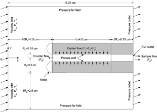
A counterflow virtual impactor (CVI) samples droplets or particles larger than a certain size by inertially separating them from the surrounding air and the smaller interstitial aerosol particles in a cloud (CitationOgren et al. 1985). By analyzing the collected samples with appropriate sensors downstream, the CVI has been widely used to study the microphysics and chemistry of clouds. A CVI can be mounted on a moving aircraft to sample cloud droplets in flight (CitationLaucks and Twohy 1998; CitationDhaniyala et al. 2003; CitationGlantz et al. 2003), or in a wind tunnel to separate cloud droplets from interstitial aerosols in ground-based measurements (CitationNoone et al. 1988; CitationSchwarzenbock and Heintzenberg 2000). A schematic diagram of the CVI is shown in . Particle separation is achieved in the CVI by injecting more clean dry carrier gas through a porous wall just inside the probe inlet than is drawn by the downstream analysis instruments. The excess carrier gas provides a counterflow through which the incoming droplets must inertially penetrate in order to be included in the sample. The counterflow is typically warmer and drier than the ambient air so that the droplets that penetrate into the sample flow are dried. Measurements then probe the nature of the cloud droplet residues thus produced. Two stagnation surfaces on which flow velocity is zero are created inside the CVI. The first stagnation surface is located near the CVI inlet, where the free stream meets the counterflow. The second stagnation surface is located further inside the CVI, where the counterflow separates from the sample flow. The shape and the position of the stagnation surface depend on the relative magnitude of the two flow rates creating the surface. Only particles with sufficient inertia or stopping distance to penetrate these two stagnation surfaces can be collected by the sampling inlet. Smaller particles escape either by following the airflow that is deflected around the CVI tip or by returning with the counterflow after passing the first stagnation surface.
The performance of a CVI is usually characterized by its collection efficiency, which is defined as the fraction of particles collected by the CVI as a function of particle size. The collection efficiency variation with droplet size depends on the geometry of the CVI, the flow field inside the CVI, and the free-stream conditions. The cut size (particle size at 50% collection efficiency) of a CVI may be estimated by a one-dimensional model based on the aerodynamic drag theory (CitationFuchs 1964), assuming the stopping distance of the particles to be the distance between the two stagnation surfaces (CitationNoone et al. 1988). The approximation has been proven to successfully predict the cut size of a CVI (CitationSchwarzenbock and Heintzenberg 2000). However, this theoretical estimate based on the simplified CVI internal and external flow fields is limited (CitationNoone et al. 1988) because it does not account for the nonaxial velocity components that determine the cut sharpness of the collection efficiency curve (CitationSchwarzenbock and Heintzenberg 2000) and the particle loss after the second stagnation surface.
Previous investigators have experimentally measured the collection efficiency curve using wet particles (droplets of ammonium sulfate solution) to calibrate the collection efficiency of large particles, whose evaporation time is long (CitationNoone et al. 1988), and dry particles (e.g., glass beads) to calibrate the collection efficiency at smaller particle sizes (CitationAnderson et al. 1993). The accuracy of the experimental collection efficiency curve is limited by uncertainties in generating, transporting, and counting calibration particles. For example, use of glass beads for the calibration may overestimate the collection efficiency of small droplets, because solid particles are likely to rebound from the wall surfaces and droplets are more likely to adhere to the wall surfaces upon impact. Although the condensed water and any dissolved gases or volatile material dissolved in the adhered droplets will be sampled, the residual particles will be left behind (CitationNoone et al. 1993). For larger droplets, the high collection efficiency assumption may not be unrealistic at large free-stream velocities due to the droplet shatter when they impact the CVI probe (CitationWeber et al. 1998; CitationSchwarzenbock and Heintzenberg 2000; CitationTwohy et al. 2003).
Numerical simulations have been effectively applied to predict the CVI collection efficiency curve as a function of geometry and flow conditions and to optimize the design of a CVI. CitationLin and Heintzenberg (1995) simulated both a simple CVI geometry and a two-dimensional (2D) axisymmetric potential flow (CitationLin and Heintzenberg 1995). With a 2D axisymmetric model, the final three-dimensional (3D) flow field is approximated by rotating the computed 2D flow field around the axis of the CVI. Results from the simplified model agreed well with prior measurements of the cut size of a CVI (CitationAnderson et al. 1993), but they predicted a much sharper cut than observed. CitationLaucks and Twohy (1998) numerically simulated the flow field and the particle trajectories for a real CVI geometry. Their model also assumed a two-dimensional axisymmetric flow but considered the effects of compressibility and turbulence and examined the mechanisms by which large particles may be lost after they survive the counterflow.
The models described above assume perfect alignment between the free stream and the CVI inlet. In the real situation, the airflow impinging on an airborne CVI probe can easily deviate by a few degrees due to mounting uncertainties, the flow turbulence, or typical aircraft maneuvers. Deviations from perfect alignment are expected to degrade the performance of the CVI because larger particles that enter the CVI at finite attack angle may directly impact the inner wall of the CVI (CitationTwohy 1992). Recently, a model was developed by CitationTwohy (1998) to study the effect of an isokinetic shroud on the flow field of the CVI. The shroud was shown to improve the alignment between the free stream flow and the CVI inlet. However, the general effect of attack angle on the collection efficiency of a CVI has not been characterized. The use of axisymmetric models precludes the study of the effect of attack angle on the collection efficiency of the CVI due to the presence of the nonaxisymmetric CVI inlet boundary condition. Since CVIs have been used in many studies without a flow-straightening shroud and continue to be so used, an understanding of the effect of finite angle of attack is needed.
In this article we describe a full 3D model of the CVI. The model allows us to study the effect of attack angle on the performance of a CVI. First, we compare the collection efficiency curve from the 3D model to those from 2D axisymmetric models. Then we present the effect of angle of attack on the collection efficiency of the CVI. Finally, we study the effect of a round nose with a diameter of 0.35 cm on the CVI performance since it is often used to reduce the turbulence (CitationLaucks and Twohy 1998).
DESCRIPTION OF THE MODEL
The computational geometry for the CVI simulations is shown in . The model simulates the region immediately outside the CVI and that inside the CVI inlet. The particular CVI we study is one that was designed to operate on a relatively low-speed aircraft. It has an inner radius of 0.15 cm and an outer radius of 0.5 cm. The porous tube inside the CVI is 4 cm long. Based on the previous modeling efforts (CitationLin and Heintzenberg 1995; CitationLaucks and Twohy 1998), the computational domain extends a few times the CVI radius beyond the outer profile, as illustrated in . For all cases, the free-stream flow conditions are assumed to be atmospheric pressure (1 atm) and 288 K. The free-stream velocity (flight velocity) is varied from 50 to 70 m/s. The sample flow rate (F2) is fixed at 5 lpm and the counterflow rate (F3) is varied from 0.1 to 1 lpm. The model assumes a 3D, steady-state, isothermal, compressible, and turbulent flow. The turbulence model employed in this study was the renormalization group (RNG) k-ϵ model, with 5% turbulence intensity and a turbulent viscosity ratio of 100 (CitationLaucks and Twohy 1998). Boundary conditions for the external flow are also shown in . The porous tube wall and the sample flow outlet are assumed to have uniform flow velocity. The rest of the CVI surfaces are assumed to be solid walls.
The computational domain is meshed into hexahedral cells with smaller cells close to the boundaries where the finer structure of the flow is desired than in the free-stream flow. During the solution process, cells close to the CVI wall surfaces were gradually refined to test the dependence of the results on cell volume. The adaptation process was terminated when the final results did not change with further refinement. The minimum volume of the cell was 3.0 × 10− 13 m3, while the maximum cell volume was 9.7 × 10− 10 m3. The total number of cells in the computational domain was on the order of 106. The mass, momentum, and turbulence equations were discretized using the first-order upwind scheme, and the pressure–velocity coupling was achieved using the semi-implicit method for pressure-linked equations (SIMPLE) algorithm (CitationPatankar 1980). The flow field was solved using the commercial computational fluid dynamics code FLUENT® (FLUENT Inc.). The convergence criterion for the continuity equation was 10− 5. The convergence criteria for the momentum, k, and ϵ equations were set at 10− 3. The mass flow rate of the counterflow was monitored and compared to its theoretical value to ensure convergence of solutions.
After flow field convergence was achieved, particle trajectories were computed using the Lagrangian discrete phase model (DPM) supported by FLUENT®. DPM applies to particles greater than 0.1 μ m. Particle sizes considered here range from 1 to 50 μ m for the interest of ambient sampling. All particles were assumed to be spherical with unit specific gravity. The particle concentration was assumed to be sufficiently low that particle–particle interactions and the effect of the particle volume fraction on the gas flow are negligible. No heat and mass transfer between particles and the gas flow was considered. As noted by CitationLaucks and Twohy (1998), droplet evaporation is not significant upstream of the second stagnation surface because the particles pass through that region rapidly, but it may affect the droplet trajectories beyond the second stagnation surface due to the long droplet residence time in the latter region. Neglect of droplet evaporation is expected to lead to a slight underestimate of the collection efficiency of the CVI (CitationLaucks and Twohy 1998). To determine the sampling efficiency, particles with a given size are released uniformly from an injection area equivalent to that of the CVI inlet on the main inlet boundary surface. The initial particle velocity is assumed to be the same as the free-stream gas velocity (flight velocity). Upon hitting the wall, the fate of droplets/particles is not well understood since they may stick, break up, or rebound (CitationLaucks and Twohy 1998; CitationSchwarzenbock and Heintzenberg 2000; CitationTwohy et al. 2003). The model considers two extreme conditions with sticky or reflecting walls to show the effect of such an uncertainty on the CVI collection efficiency. For sticky walls, particles stick to the wall upon impaction. For reflecting walls, particles rebound from the wall surfaces upon impaction. The collection efficiency is defined as the ratio of the number of particles passing the CVI outlet to the total number of particles released. However, it should be noted that droplet impaction on the walls would not affect the collection efficiency for volatile nonreactive gases such as water vapor.
RESULTS AND DISCUSSION
Comparison of the Full 3D Model to Axisymmetric Models
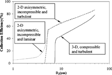
compares the results from three different models for a flight velocity of 70 m/s, a counterflow of 0.1 lpm, and an attack angle of 0ˆ. Two of the simulations are based on the axisymmetric flow, while the third simulation employs a full 3D model without the axisymmetric flow assumption. For the axisymmetric simulations, both the cut sharpness and the critical size (the minimum particle size that is collected by the CVI) of the collection efficiency curve increase when a turbulent-flow model was employed instead of a laminar model. The difference in the collection efficiency curve may be attributed to the effect of turbulent mixing on the shape of the first stagnation surface. With the additional mixing allowed in the turbulent model, the first stagnation surface becomes more uniform (flatter) and the distance between two stagnation surfaces is more uniform. Consequently, the required stopping distance for particles to penetrate the stagnation surfaces is more uniform, which corresponds to a sharper cutoff in the collection efficiency curve. For the particular set of operating conditions, the flow outside the CVI inlet has a Reynolds number of 4.6 × 10⁴ based on the outer diameter of the CVI; hence, the flow is turbulent, although the flow inside the CVI is still laminar (Re = 2,000). For the full 3D simulations, the computed critical size increased over that predicted by the axisymmetric simulations but the collection efficiency decreased at any given particle size. The difference between the efficiency curves resulting from 2D and 3D models may be explained by the additional turbulent mixing effects along the third direction (circumferential) allowed in the 3D model, which more closely approximates the actual flow geometry.
Effect of Angle of Attack
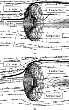
The local flow streamlines inside and outside the CVI near the inlet and four selected particle trajectories are shown in for a flight velocity of 70 m/s and a counterflow rate of 0.1 lpm. is for an angle of attack of 0ˆ, and is for an angle of attack of 5ˆ. Based on the flow streamlines, the first stagnation surface (less visible) occurs near the CVI inlet where the free stream meets the counterflow and the second stagnation surface occurs further inside the CVI where the counterflow separates from the sample flow.
Figure 4 Flow streamlines inside and outside the CVI near the inlet for a flight velocity Uo = 70 m/s, a counterflow F3 = 0.1 lpm, and two attack angles (a) α = 0ˆ and (b) α = 5ˆ. Also shown are trajectories for particles 1–4 with aerodynamic diameters of 1, 7.5, 14, and 20.5 μ m, respectively.
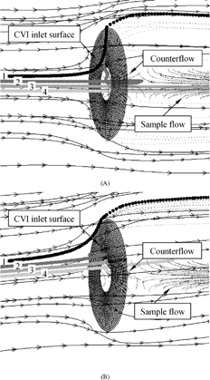
The particle trajectories represented by discrete spheres are for particles 1–4 with aerodynamic diameters of 1, 7.5, 14, and 20.5 μ m, respectively. These particles are all released from the line intersected by the flow entrance plane in the computational domain and the vertical symmetry plane of the CVI, but with different distance from the CVI axis. Particles 1 and 2 are released from 0.06 and 0.02 cm above the CVI axis, respectively. Particles 3 and 4 are released from 0.02 and 0.06 cm below the CVI axis. Particle 1 (1 μ m) has a relatively small size, so it follows the airflow in front of the CVI inlet for both attack angles. At 0ˆ attack angle, particle 2 (7.5 μ m) can penetrate the first stagnation surface, but it does not have sufficient inertia to penetrate the second stagnation surface. As a result, particle 2 returns with the counterflow after passing the first stagnation surface and is finally trapped on the inlet wall of the CVI. With 5ˆ attack angle, particle 2 directly impacts the CVI inlet wall and gets stuck. Particles 3 (14 μ m) and 4 (20.5 μ m) have sufficient inertia to penetrate both stagnation surfaces and enter the CVI when the attack angle is 0ˆ. With an attack angle of 5ˆ, both particles are lost by impaction on the porous wall of the CVI.
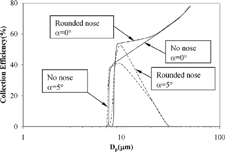
The overall collection efficiencies of the CVI for angles of attack of 0ˆ and 5ˆ are plotted in , assuming both sticky and reflecting CVI inner walls. The left set of three curves shows the results for a flight velocity of 70 m/s and a counterflow rate of 0.1 lpm, while the right set of three curves is for a flight velocity of 50 m/s and a counterflow rate of 1 lpm. The solid curve in each set is for an attack angle of 0ˆ and a sticky wall, while the dashed curve is for an attack angle of 0ˆ and a reflecting wall. The dash-dotted curve is for an attack angle of 5ˆ and a sticky wall. As expected, the collection efficiency of the CVI with a reflecting wall is much higher than that with a sticky wall, but the collection efficiency curves are less steep near the critical size with reflecting walls. The critical size increases with decreasing free-stream velocity and increasing counterflow rate. At a flight velocity of 70 m/s and a counterflow of 0.1 lpm, the critical size of the CVI is about 7 μ m. The critical size increases to about 11 μ m when the flight velocity is reduced to 50 m/s and the counterflow rate is increased to 1 lpm. The increase in the critical size is explained by the increase of the distance between the two stagnation surfaces. Although it is difficult to quantitatively characterize the distance between two stagnation surfaces due to their curvatures, the qualitative increase of the separation between two stagnation surfaces with decreasing free-stream velocity and increasing counterflow rate has been observed from the modeling results. Based on the aerodynamic drag theory (CitationFuchs 1964), larger particle inertia or stopping distance is required to pass the two stagnation surfaces. This result is qualitatively similar to what has been found in the earlier models (CitationLin and Heintzenberg 1995; CitationLaucks and Twohy 1998). For a particle size greater than 20 μ m, the effects of the flight velocity and the counterflow on the collection efficiency diminish and the CVI has the same efficiency characteristics for both sets of operating conditions.
Figure 5 Effects of attack angle on the collection efficiency of the CVI for various flow and porous wall conditions.
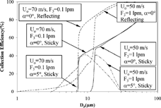
The attack angle of free-stream flow has a negligible effect on the critical size and cut sharpness of the collection efficiency curve of the CVI. However, the collection efficiency of the CVI at larger particle sizes is greatly degraded with an attack angle of 5ˆ. Since the trend is the same for both sets of operating conditions, we discuss the left set of the curves with a sticky wall as an illustration. For an attack angle of 0ˆ and a flight velocity of 70 m/s, the collection efficiency curve starts with a critical size of 7.25 μ m and rises steeply to 40% at 8 μ m. The collection efficiency increases but with a slower rate with increasing particle size for particles greater than 8 μ m. With a particle size of 50 μ m, the collection efficiency reaches about 80%. With an attack angle of 5ˆ and the same flight speed, the critical size of the CVI slightly decreases to 7 μ m, but the collection efficiency rises with the same rate as the case for 0ˆ attack angle for particle sizes up to 10 μ m. At 10 μ m, the collection efficiency reaches 40%. The collection efficiency degrades drastically with increasing particle size for particles larger than 10 μ m. As a result, the 5 o CVI can only collect particles near the transmission efficiency peak (about 10 μ m) and rejects all other particle sizes. Smaller particles have too little inertia to penetrate the counterflow region, while larger particles tend to maintain their direction after entering the CVI inlet but impact on the inner wall of the CVI. With a sticky wall, these particles are lost to the CVI inner wall and are not collected by the CVI.
Effect of the Nose
The significant degradation of the collection efficiency for larger particle sizes at a 5ˆ attack angle is a problem for many applications. Rounded inlets reduce the turbulence and the sensitivity to angle of attack over sharp-edged inlets (CitationLaucks and Twohy 1998), so we examined the influence of adding a round nose to the blunt CVI. As shown in , the nose considered has a diameter of the thickness of the CVI wall (0.35 cm). shows a comparison of the streamlines near the round-nose CVI inlet and 4 particle trajectories for attack angles of 0ˆ and 5ˆ, and the same operating conditions as used in . Both a reflecting nose (particles are reflected back into the flow upon impacting the nose) and a sticky nose (particles stick to the wall upon impacting the nose) are considered, but the particle trajectories shown in are for sticky noses only. The round nose reduces the flow separation, as can be seen from the smoother streamlines and thinner flow boundary layer shown in compared to . However, the nose does not change the fate of the four particles considered.
Figure 6 Flow streamlines inside and outside the round-nose CVI near the inlet for a flight velocity Uo = 70 m/s, a counterflow F3 = 0.1 lpm, and two attack angles (a) α = 0ˆ and (b) α = 5ˆ. Also shown are trajectories for particles 1–4 with aerodynamic diameters of 1, 7.5, 14, and 20.5 μ m, respectively.
The effect of the nose on the overall collection efficiency of the CVI is shown in for a flight velocity of 70 m/s and a counterflow rate of 0.1 lpm. Solid curves are for a 0ˆ attack angle; the dashed curves are for an attack angle of 5ˆ. For each attack angle, only two extreme cases (no nose and reflecting nose) are plotted. As expected based on the aerodynamic drag theory (CitationFuchs 1964), the presence of the nose slightly increases the critical size of the CVI due to the increase of the distance between two stagnation surfaces. For a reflecting nose, all particles hitting the nose rebound elastically, so the nose increases the collection efficiency for particles slightly larger than the critical size at both attack angles. The reflecting nose has no effect on the collection efficiency of further larger particles for both attack angles. If a sticking nose is assumed, the only effect of the nose on the collection efficiency is a small increase in the critical size. The collection efficiency curve of a CVI with a sticky nose hence follows that of a CVI without the nose for particles larger than the critical size.
CONCLUSIONS
The collection efficiency of an airborne CVI was predicted using a full 3D simulation based upon FLUENT®. The model predicts a larger critical size but a lower efficiency than does a 2D axisymmetric model. In agreement with the aerodynamic drag theory and prior models, the model confirms that the critical size of the collection efficiency curve increases with the increase of counterflow rate and the decrease of flight velocity. The CVI collection efficiency is very sensitive to the flight angle of attack. With an attack angle of as small as 5ˆ, the collection efficiency for particles slightly larger than the critical size starts to degrade drastically. As a result, the CVI can only collect particles with intermediate sizes, i.e. particles near the critical size. Larger particles are lost to the CVI inner walls due to the direct impaction with a small attack angle. The addition of a round nose at the blunt CVI inlet slightly increases the critical size of the collection, but it does not improve the collection efficiency of large particles when a non-zero attack angle is present. Measures to improve the alignment between the incoming flow and the CVI inlet are critical to the performance of the CVI. Notably, use of a shroud to straighten the airflow into the CVI should alleviate the impact of the flight attack angle on the collection efficiency of the CVI.
REFERENCES
- Anderson , T. L. , Charlson , R. J. and Covert , D. S. 1993 . Calibration of a Counterflow Virtual Impactor at Aerodynamic Diameters from 1 to 15 μ m . Aerosol Sci. Technol. , 19 ( 3 ) : 317 – 329 .
- Dhaniyala , S. , Flagan , R. C. , McKinney , K. A. and Wennberg , P. O. 2003 . Novel Aerosol/Gas Inlet for Aircraft-based Measurements . Aerosol Sci. Technol. , 37 ( 10 ) : 828 – 840 . [CSA] [CROSSREF]
- FLUENT Inc. http://www.fluent.com.
- Fuchs , N. A. 1964 . The Mechanics of Aerosols , New York : Dover Publications .
- Glantz , P. , Noone , K. J. and Osborne , S. R. 2003 . Comparisons of Airborne CVI and FSSP Measurements of Cloud Droplet Number Concentrations in Marine Stratocumulus Clouds . J. Atmos. Oceanic Technol. , 20 ( 1 ) : 133 – 142 . [CSA] [CROSSREF]
- Laucks , M. L. and Twohy , C. H. 1998 . Size-dependent Collection Efficiency of an Airborne Counterflow Virtual Impactor . Aerosol Sci. Technol. , 28 ( 1 ) : 40 – 61 .
- Lin , H. and Heintzenberg , J. 1995 . A Theoretical-Study of the Counterflow Virtual Impactor . J. Aerosol Sci. , 26 ( 6 ) : 903 – 914 . [CROSSREF]
- Noone , K. B. , Noone , K. J. , Heintzenberg , J. , Strom , J. and Ogren , J. A. 1993 . In Situ Observations of Cirrus Cloud Microphysical Properties Using the Counterflow Virtual Impactor . J. Atmos. Oceanic Technol. , 10 ( 3 ) : 294 – 303 . [CSA] [CROSSREF]
- Noone , K. J. , Ogren , J. A. , Heintzenberg , J. , Charlson , R. J. and Covert , D. S. 1988 . Design and Calibration of a Counterflow Virtual Impactor for Sampling of Atmospheric Fog and Cloud Droplets . Aerosol Sci. Technol. , 8 ( 3 ) : 235 – 244 . [CSA]
- Ogren , J. A. , Heintzenberg , J. and Charlson , R. J. 1985 . In-Situ Sampling of Clouds with a Droplet to Aerosol Converter . Geophys. Res. Lett. , 12 ( 3 ) : 121 – 124 . [CSA]
- Patankar , S. V. 1980 . Numerical Heat Transfer and Fluid Flow , Washington , DC : Hemisphere .
- Schwarzenbock , A. and Heintzenberg , J. 2000 . Cut Size Minimization and Cloud Element Break-up in a Ground-based CVI . J. Aerosol Sci. , 31 ( 4 ) : 477 – 489 . [CSA] [CROSSREF]
- Twohy , C. H. 1992 . On the Size Dependence of the Chemical Properties of Cloud Droplets: Exploratory Studies by Aircraft , Seattle : University of Washington . Ph.D. Thesis
- Twohy , C. H. 1998 . Model Calculations and Wind Tunnel Testing of an Isokinetic Shroud for High-speed Sampling . Aerosol Sci. Technol. , 29 ( 4 ) : 261 – 280 .
- Twohy , C. H. , Strapp , J. W. and Wendisch , M. 2003 . Performance of a Counterflow Virtual Impactor in the NASA Icing Research Tunnel . J. Atmos. Oceanic Technol. , 20 ( 6 ) : 781 – 790 . [CSA] [CROSSREF]
- Weber , R. J. , Clarke , A. D. , Litchy , M. , Li , J. , Kok , G. , Schillawski , R. D. and McMurry , P. H. 1998 . Spurious Aerosol Measurements When Sampling from Aircraft in the Vicinity of Clouds . J. Geophys. Res.—Atmos. , 103 ( D21 ) : 28337 – 28346 . [CSA] [CROSSREF]

