Abstract
Cone-beam CT (CB-CT) based image-guidance was evaluated for extracranial stereotactic radiotherapy of intrapulmonary tumors. A total of 21 patients (25 lesions: prim. NSCLC n = 6; pulmonary metastases n = 19) were treated with stereotactic radiotherapy (1 to 8 fractions). Prior to every fraction a CB-CT was acquired in treatment position, errors between planned and actual tumor position were measured and corrected. Intra- and inter-observer variability of manual evaluation of tumor position error was investigated and this manual method was compared with automatic image registration. Based on CB-CTs from 66 fractions the discrepancy (3-D vector) between planned and actual tumor position was 7.7 mm ±1.3 mm. Tumor position error relative to the bony anatomy was 5.3 mm ±1.2 mm, the correlation between bony anatomy and tumor position was poor. Intra-observer and inter-observer variability of manual evaluation of tumor position error was 0.9 mm ±0.8 mm and 2.3 mm ±1.1 mm, respectively. Automatic image registration showed highly reproducible results (<1 mm). However, compared with manual registration a systematic error was found in direction of predominant tumor breathing motion (2.5 mm vs 1.4 mm). Image-guidance using CB-CT was validated for high precision radiotherapy of intrapulmonary tumors. It was shown that both the planning reference and the verification image study have to consider tumor breathing motion.
The standard treatment for primary early-stage non–small-cell lung cancer (NSCLC) without distant metastasis and for solitary lung metastases from selected primaries (e.g. colorectal cancer) is surgical resection. With surgery alone 5-year survival rates of more than 60% were reported in patients with stage I NSCLC Citation[1]. For medically inoperable patients, radiotherapy is the treatment of choice. However, with standard doses of about 65 Gy and standard fractionation schemes, the results are suboptimal and local failure was identified as the most common mode of failure. Higher doses were associated with improved rates of local control and higher rates of local control were significantly correlated with improved survival Citation[2], Citation[3].
Based on a dose-response relationship, Martel estimated that doses higher than 84 Gy are necessary to achieve long-term local control Citation[4]. Dose escalation studies with conventional fractionation improved rates of local control but resulted in substantial toxicity and suffer from longer treatment time Citation[5].
Lax and Blomgren adapted the stereotactic technique from treatment of intracranial lesions to treatment of intrapulmonary and intrahepatic tumors Citation[6]. Immobilization of the patient within a stereotactic bodyframe (SBF) and reduction of tumor mobility by abdominal compression resulted in reduced target volumes. This treatment technique with reduced normal tissue inside the planning target volume (PTV) allowed the safe application of hypo-fractionated, escalated doses – higher doses than possible with standard treatment techniques. Recently, McGarry et al. reported a phase I dose escalation study for early-stage NSCLC. For stage T1, the maximum tolerated dose was not achieved with 3 fractions of 20 Gy; for stage T2, the maximum tolerated dose was realized at 3×24Gy for tumors larger than 5 cm Citation[7].
Due to different fractionation schemes, methods of dose prescription, target volume concepts and total doses reported in the literature the optimal treatment regime still remains unclear. However, a dose-response relationship in stereotactic treatment of intrapulmonary tumors was demonstrated Citation[8] and Onishi et al. reported excellent three-year survival rates of 88.4% for medically operable patients with stage I NSCLC if the biologic effective doses (BED) were higher than 100 Gy Citation[9].
The stereotactic treatment technique is based on the hypothesis of a fixed relationship between the target and a system of external coordinates. Standard margins of 5 mm in the axial plane and 10 mm in the longitudinal direction are applied to the gross target volume (GTV) to compensate set-up errors and motion of the target. However, studies using CT simulation for verification of the tumor position prior to treatment showed significant deviations of planned and actual target position at treatment and the reliability on bony landmarks was poor Citation[10], Citation[11]. Soft-tissue imaging should therefore increase precision in extracranial stereotactic treatment.
Within this study we report initial results of using a cone-beam CT (CB-CT) for verification of the tumor position in stereotactic treatment of intrapulmonary lesions. The CB-CT offers the opportunity to acquire a three-dimensional (3-D) image set with sufficient soft-tissue contrast in treatment position without the need of moving the patient or the treatment table. The image quality of the CB-CT for high precision stereotactic treatment was evaluated. Set-up errors of the patient and errors between planned and actual tumor position were measured, intra-observer and inter-observer variability was tested. For quality assurance of this image-guided treatment protocol manual and automatic evaluation of tumor position errors were compared.
Materials and methods
Starting in August 2005 a total of 21 consecutive patients with 25 intrapulmonary lesions were treated with hypo-fractionated stereotactic radiotherapy by use of image-guidance with CB-CT. Indications for treatment were pulmonary metastases (maximum number of 3 lesions per patient) and early stage NSCLC (T1 N0 and T2 N0). Two patients were treated for stage T2 NSCLC with positive lymph nodes in the mediastinum: the primary tumor was treated with 3×12.5 Gy prescribed to the PTV surrounding 65% isodose whereas the lymphatics were treated with normo-fractioned treatment to a total dose of 50 Gy. Patient and treatment characteristics are summarized in . Position and mobility of all treated lesions (estimated at treatment planning) is displayed in .
Figure 1. Position and mobility of all 25 treated lesions (Figure 1A frontal view, Figure 1B lateral view). The size of the treated lesions is not considered in this figure. Light grey: movement < 5 mm; dark grey: movement 5 mm to 10 mm; black: movement > 10 mm.
Table I. Treatment and patient characteristics.
Treatment planning
Treatment planning and patient set-up has been described previously Citation[12], Citation[13]. Briefly, patients were immobilized in a SBF (Elekta, Crawly, UK) and breathing mobility was reduced mechanically by abdominal pressure if target motion was more than 5 mm in superior-inferior direction.
Delineation of target volume and organs-at-risk (OAR) and treatment planning was done on a CT study with slice thickness of 5 mm. Patients were instructed to maintain free shallow breathing. Breathing mobility was derived from dynamic CT-scanning (repeated CT scanning at the same table position, 15 s, one image per second) and from CT studies in deep inspiration and deep expiration. The GTV, the visible tumor including spiculae, was delineated in the CT pulmonary window; no additional margin was added for generation of the CTV. An internal target volume (ITV) was generated including tumor positions in all dynamic CT studies and tumor positions in deep inspiration and deep expiration. A 3-D ITV-to-PTV margin of 5 mm was applied to compensate intra-fractional changes of tumor position and tumor breathing motion. This way of target definition resulted in asymmetrical “CTV-to-PTV margins” if the planning CT study (acquired in free shallow breathing) showed the tumor in a position close to deep inspiration or close to deep expiration. Three-dimensional conformal multifield treatment techniques were used. The dose was prescribed to the PTV-enclosing isodose and normalized to 100% maximum dose.
Depending on tumor size and tumor location, different fractionation schemes were applied. In general, radiosurgery with a single fraction of 26 Gy prescribed to the 80% PTV surrounding isodose was chosen for small targets and for targets with peripheral location. Fractionated treatment schemes were chosen in cases of large tumors, central location and close proximity to critical structure like large vessels and bronchi: 3 fractions of 12.5 Gy prescribed to the 65% isodose line.
Treatment set-up and verification of tumor position
The treatment protocol practiced at our clinic is characterized by 3-D volume imaging using an onboard CB-CT and online correction of tumor position errors.
The CB-CT system is a combination of a kV-source and an aSi flat-panel installed on the Elekta Synergy S™ linear accelerator. CB-CTs with a voxel size of typically 1 mm can be acquired in treatment position without the need of moving the patient or the treatment couch. For acquisition of a CB-CT study with a medium field of view (42 cm diameter) a 360o rotation of the gantry is necessary, which takes about 90 s.
The patient was positioned in the SBF and the planned isocenter was adjusted based on the system of external coordinates on the SBF. In treatment position a CB-CT study was acquired. The discrepancy between planned and actual tumor position was evaluated manually using the Elekta XVI™ software: the ITV and PTV structures from the planning CT study were projected into the current CB-CT study and the position of these structures was corrected by shifting until they perfectly enclosed the visible tumor in the CB-CT study. Based on this manual registration the errors were calculated by the XVI software. This process of manual registration is displayed in . Errors were corrected by an adjustment of the treatment table position.
Figure 2. Registration of planning CT study and verification cone-beam CT (CB-CT) study: Structures of the ITV (inner contour) and the PTV (outer contour) are projected into the CB-CT study and adjusted to the tumor position at time of treatment.
Evaluation of inter-fractional tumor position stability and quality assurance of image-guidance using CB-CT
Based on the verification CB-CT studies acquired before treatment, different errors were calculated:
Set-up error of the bony anatomy inside the SBF (patient positioning error);
Tumor position error relative to the stereotactic coordinates of the SBF;
Tumor position error relative to the bony anatomy.
The tumor position error, the discrepancy between planned and actual tumor position, relative to the external SBF coordinates was measured manually as described above. Intra-observer variability of this manual process was investigated: at least one week after treatment all CB-CT studies were reexamined by the same physician. Additionally, all CB-CT studies were examined by a second physician: tumor position errors were manually evaluated and inter-observer variability was tested.
The performance of a grey-value matching algorithm, a correlation coefficient algorithm, (Elekta XVI software) was tested for an automatic image registration of the planning CT study and the verification CB-CT study. All CB-CT studies were evaluated three times: for two registrations the same alignment box was used and for the third registration an enlarged box with increased normal tissue inside was applied. The alignment box confines the volume of interest of the automatic registration.
The displacement of the tumor relative to the bony anatomy was calculated by a subtraction of the absolute tumor displacement minus the patient positioning error.
Systematic and random components of these errors were calculated. Errors are reported as described by van Herk Citation[14]; for each patient the mean (systematic error) and standard deviation (random error) of the errors in each of the three axes were calculated. For patients treated with a single fraction no random error was assumed. The systematic error for all patients was calculated as the average of the absolute systematic errors of all patients, the random error was calculated as the average of all individual random errors. The group mean error was calculated as the average value of all fractions from all patients and indicates systematic discrepancies between planning and treatment for the whole patient collective.
For statistical analysis Statistica 6.0 (Statsoft, Tulsa, USA) was utilized. Differences were considered significant for p < 0.05. For test of correlation the Spearmen's rank test was used.
Results
Clinical implementation and image quality of CB-CT
The protocol with CB-CT imaging prior to the treatment, manual registration of planning and verification CT study and correction of set-up errors added about 10 min to the total treatment time. Total treatment time was dependent on the dose per fraction and the number of beams and ranged between 30 min to 45 min. The manual registration took about 5 min compared with 30 s needed for an automatic registration of planning and verification CT study. All patients successfully finished their treatment.
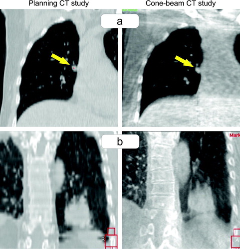
The image quality of the CB-CT was sufficient for verification of the tumor position in all cases. No lesion was treated based on stereotactic coordinates, only. Lesions with a minimum diameter of 5 mm were visible in the CB-CT (a). The registration process was difficult for three tumors with location close to the diaphragm: the inferior part of the blurred tumor was hardly distinguishable from the blurred diaphragm (b). In direction of the predominant tumor motion a blurred transition of the CT grey-values from the tumor to the surrounding pulmonary tissue was seen for moving tumors. The size of the PTV was sufficient to cover the blurred tumor completely in all cases.
Figure 3. Image quality of the cone-beam CT in comparison to the planning CT study. a) Patient treated for a 5 mm small lesion attached at the mediastinum. b) Patient treated for a supra-diaphragmatic lesion where the blurred inferior part of the tumor overlapped with the blurred diaphragm.
As follow-up is too short (median follow-up 3 months), data of local control and survival will not be reported in detail. However, all patients are locally controlled and no acute or late toxicity was recorded so far.
Tumor position errors measured prior to treatment
Patient positioning, the set-up error of the bony anatomy in the SBF, showed systematic and random positioning errors (mean ±standard deviation) of 3.2 mm ±2.1 mm in SI direction, 2.6 mm ±1.1 mm in AP direction and 1.8 mm ±2.0 mm in LR direction. Detailed results are listed in . The group mean error of 1.5 mm towards dorsal indicates a small systematic error of patient positioning between planning and treatment. Rotational errors around all three axes were usually less than 1o and therefore considered negligible for small and spherical target volumes Citation[15]. For one single patient a systematic rotational error of 2.9o around the LR axis was calculated.
Table II. Patient set-up errors and tumor position errors relative to external SBF coordinates and relative to the bony anatomy.
Relative to SBF coordinates substantial discrepancies between planned and actual tumor position were measured (). Systematic and random errors were 3.7 mm ±2.1 mm in SI direction, 4.9 mm ±1.4 mm in AP direction and 2.3 mm ±2.2 mm in LR direction. A group mean error of 3.2 mm in the posterior direction was calculated; only minor group mean errors (maximum 1.1 mm) were seen in the other directions.
Positioning errors of the bony anatomy (the vertebral spine on the level of the treated lesion) and the tumor position errors were plotted in : a slope of 0.99 and a R2 of 0.50 were calculated. Clinically relevant tumor position errors relative to the bony anatomy were seen (): systematic and random errors of 2.1 mm ±1.1 mm in SI direction, 3.3 mm ±1.3 mm in AP direction and 2.2 mm ±1.1 mm in LR direction were found. The 3-D translational vector with 5.3 mm ±1.2 mm was only marginally smaller than the error relative to SBF coordinates with 7.8 mm ±1.6 mm. shows the distribution of tumor position errors (all three axes) relative to the SBF coordinates (a) and relative to the bony anatomy (b).
Figure 4. Correlation between set-up errors of the bony anatomy (x-axis) and tumor position errors relative to external coordinates of the stereotactic bodyframe (y-axis).
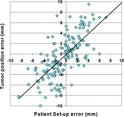
Figure 5. Distribution of tumor position errors (all three axes) relative to external coordinates of the stereotactic bodyframe (a) and relative to the bony anatomy (b).
In Spearmen's rank test a significant correlation between the PTV/CTV ratio and tumor position errors relative to the bony anatomy was found (p = 0.03). Large PTV/CTV ratios resulted in large tumor positioning errors. The location of the tumor (central, close to chest wall, close to mediastinum) had no influence of this tumor position error. Tumor position errors were not different between patients where the diaphragm control was used compared with free breathing patients.
Quality assurance of CB-CT for image guidance
The intra-observer variability of the manual measurement of the tumor position error was investigated. All CB-CT studies were re-evaluated by the same physician. Compared with the original results differences larger than 1 mm and 2 mm were seen in 35% and 8% of all measurements, respectively. The mean difference was 0.9 mm ±0.8 mm and the maximum difference was 3.5 mm. The intra-observer variability was similar in all three directions. No clinical or planning parameter was found to be correlated with the intra-observer variability (tumor location, PTV volume, PTV/CTV ratio).
The inter-observer variability showed a mean 3-D difference of 2.3 mm ±1.1 mm, the maximum difference was 4.4 mm; the tumor of this patient was located in the right costophrenic angle. No significant correlation between clinical or planning parameters and the inter-observer variability was seen.
The grey-value matching algorithm for an automatic registration of the planning CT study and the verification CB-CT study showed highly reproducible results; in 96% of all measurements the results between two automatic registrations differed less than 1 mm. The size of the alignment box and consequently the amount of lung tissue inside the box did not influence the results of the automatic registration. However, bony anatomy should be excluded from this alignment box; the matching algorithm seemed to “focus” on the bony anatomy resulting in large registration errors (>5 mm) in cases without fix relation between tumor and bony anatomy.
The results from the manual registration were compared with errors calculated with the automatic grey-value registration. Differences larger than 1 mm and 2 mm were found in 61% and in 37%, respectively. A maximum difference of 5.2 mm was seen. The difference between manual and automatic measured errors was significantly larger in directions with predominant tumor motion (AP direction for 10 targets and SI for 15 targets) compared with the other directions: 2.5 mm versus 1.4 mm (p < 0.05). Detailed results are shown in .
Table III. Differences between automatically and manually measured errors of the tumor position.
Discussion
An image-guided protocol for stereotactic treatment of intrapulmonary tumors was presented and evaluated. CB-CT based volume imaging for verification of the tumor position prior to the treatment and online correction of these errors are the key characteristics of this protocol. The work-flow proved to be feasible in daily clinical practice and 21 patients with 25 lesions were successfully treated. A total of 66 CB-CTs were evaluated within this study.
Several studies using CT simulation before treatment raised the question whether a system of external coordinates is a reliable surrogate for the tumor position at treatment. summarizes published position errors of intra-pulmonary and intra-hepatic targets in relation to a system of external coordinates Citation[10], Citation[11], Citation[16]. Different types of targets, different immobilization devices, different imaging devices and different methods for evaluation of the verification CT studies make the comparison of these data difficult. However, in general these data clearly indicate that in treatment with reliance on stereotactic coordinates without additional imaging a substantial error has to be taken into account.
Table IV. Published data of tumor position errors relative to external stereotactic coordinates.
A group mean error of the tumor position of 3.2 mm in the posterior direction was observed between planning and treatment. About half of this error can be attributed to a systematic positioning error of the patients in the SBF; the other half of this error was result of a systematic displacement of the tumor inside the bony chest. This error was not different between the first treatment fraction and the following fractions. Loss of vacuum in the cushion is therefore unlikely to be responsible for this error – the integrity of the used vacuum cushions was checked and verified. We suppose that patients were more accustomed to the positioning in the SBF and the increased relaxation of the dorsal muscles caused the systematic posterior positioning error.
Wulf et al. reported about displacements of mobile soft-tissue tumors relative to the bony anatomy Citation[11]: errors (one SD) of ±4.5 mm, ±5.2 mm and ±3.3 mm in SI, AP and LR direction were measured, respectively. A poor correlation between the position errors of the bony anatomy and the soft-tissue tumor itself was seen. Our data recapitulate this finding. The mean error of the tumor position (3-D vector) was 7.7 mm ±1.3 mm relative to the SBF coordinates and 5.3 mm ±1.2 mm relative to the bony anatomy.
The tumor position errors relative to the bony anatomy were correlated with the PTV/CTV ratio, indicating increased tumor position variability for tumors with increased range of breathing motion. Simultaneously, the intra-observer variability of the manual image registration process was not influenced by this PTV/CTV ratio. Therefore these data indicate that the position of the moving tumor, the mean tumor position, is not stable within the bony chest and daily soft-tissue imaging may be necessary.
The calculated errors of the tumor position did not result from the way of target definition. The PTV was not based on a single CT study. It was shown that a single CT study may display the tumor in a non representative position resulting in errors larger than 10 mm Citation[17]. The ITV in this study included the tumor positions in deep inspiration, deep expiration and in dynamic CT scans (15 s with one image per second).
With an image acquisition time of about 1.5 min the CB-CT produces images similar to slow-CT scanners; moving organs are blurred in direction of the movement. Different authors used slow-CT-scanners for treatment planning of moving intrapulmonary tumors Citation[18–20]. They consistently reported that a single slow-CT depicts all positions or a great part of the different topographical positions of moving lung tumors compared with multiple fast-CTs. Therefore the CB-CT acquired prior to treatment not only provides information about the position of the tumor but also about the range and pattern of tumor motion.
Evaluation of tumor position errors was based on manual registration of planning structures and tumor position in the CB-CT. Both the ITV and PTV structures from treatment planning and the CB-CT incorporated information about the motion of the tumor. Consequently, neglect of 4-D information is not responsible for these tumor position errors relative to the bony anatomy. Both intra-observer and inter-observer variability of this manual registration were investigated and variability of 0.9 mm ±0.8 mm and 2.3 mm ±1.1 mm was found, respectively.
The automatic image registration between planning CT and verification CB-CT was found to be highly reproducible. However, a systematic error between the manual evaluation of tumor position error and the automatic image registration was observed. Differences between manual evaluation of tumor position error and automatic image registration were correlated with the direction of the tumor motion: in direction of the predominant tumor motion differences were significantly larger than in directions with no or only small tumor motion. The planning CT study was acquired in free shallow breathing and therefore showed the tumor in a random position of the breathing cycle. To utilise an automatic image registration process for evaluation of the tumor position error all imaging modalities have to consider 4-D tumor breathing motion Citation[17], Citation[21].
Another major difference between this study and published data about inter-fractional and intra-fractional stability of tumor position is the use of a volume imaging device, a CB-CT, installed on the linac. No movement of the patient or change of the treatment couch position was necessary for image acquisition. Errors due to a transfer process of the patients are eliminated by using an integrated imaging device. Lehmann et al. demonstrated that rotation of the treatment table for image acquisition with an in-room CT may generate errors up to 6.3 mm Citation[22]; differences in table sag between treatment and imaging position and differences between treatment and imaging isocenter were responsible for this error.
Based on these results the work-flow for hypo-fractionated treatment of intrapulmonary lesions at our clinic is moving away from the traditional stereotactic technique. Image-guidance with soft-tissue imaging and online correction of tumor position errors characterise the described technique. The stereotactic bodyframe is only used for immobilization of the patient and application of the abdominal compression. Uematsu et al. described frameless stereotactic treatment by use of an in-room CT-scanner and reported excellent clinical results Citation[23]. Besides kilovoltage CB-CT other linac integrated imaging devices offer volume imaging with sufficient soft-tissue contrast like helical tomotherapy Citation[24] and megavoltage cone-beam CT Citation[25]. These imaging devices integrated into the linac will not only increase precision but reduce work-load, streamline the work-flow and accelerate treatment time. This is prerequisite to make this promising technique of hypo-fractionated treatment of intrapulmonary lesions available to a broader community in radiation oncology.
Conclusion
Image-guidance using CB-CT was validated for high precision radiotherapy of intrapulmonary tumors. Low reproducibility of the tumor position relative to external stereotactic coordinates and relative to the bony anatomy was observed resulting in substantial tumor position errors. Large safety margins were found to be necessary for compensation of these errors. Therefore soft-tissue imaging seems to increase precision and subsequently image-guidance will allow a reduction of safety margins. Manual evaluation of tumor position error was found to be reproducible. To utilize an automatic image registration for evaluation of tumor position error both the planning CT study and the imaging for verification of the tumor position at treatment have to consider 4-D tumor motion.
This work was partially presented at the 3rd Acta Oncologica Symposium on Stereotactic Body Radiotherapy.
References
- Nesbitt JC, Putnam JB, Jr, Walsh GL, et al. Survival in early-stage non-small cell lung cancer. Ann Thorac Surg 1995; 60: 466–72
- Jeremic B, Classen J, Bamberg M. Radiotherapy alone in technically operable, medically inoperable, early-stage (I/II) non-small-cell lung cancer. Int J Radiat Oncol Biol Phys 2002; 54: 119–30
- Sibley GS, Jamieson TA, Marks LB, et al. Radiotherapy alone for medically inoperable stage I non-small-cell lung cancer: The Duke experience. Int J Radiat Oncol Biol Phys 1998; 40: 149–54
- Martel MK, Ten Haken RK, Hazuka MB, et al. Estimation of tumor control probability model parameters from 3-D dose distributions of non-small cell lung cancer patients. Lung Cancer 1999; 24: 31–7
- Bradley J, Graham MV, Winter K, et al. Toxicity and outcome results of RTOG 9311: A phase I-II dose-escalation study using three-dimensional conformal radiotherapy in patients with inoperable non-small-cell lung carcinoma. Int J Radiat Oncol Biol Phys 2005; 61: 318–28
- Blomgren H, Lax I, Naslund I, et al. Stereotactic high dose fraction radiation therapy of extracranial tumors using an accelerator. Clinical experience of the first thirty-one patients. Acta Oncol 1995; 34: 861–70
- McGarry RC, Papiez L, Williams M, et al. Stereotactic body radiation therapy of early-stage non-small-cell lung carcinoma: Phase I study. Int J Radiat Oncol Biol Phys 2005; 63: 1010–5
- Wulf J, Baier K, Mueller G, et al. Dose-response in stereotactic irradiation of lung tumors. Radiother Oncol 2005; 77: 83–7
- Onishi H, Araki T, Shirato H, et al. Stereotactic hypofractionated high-dose irradiation for stage I nonsmall cell lung carcinoma: Clinical outcomes in 245 subjects in a Japanese multiinstitutional study. Cancer 2004; 101: 1623–31
- Herfarth KK, Debus J, Lohr F, et al. Extracranial stereotactic radiation therapy: Set-up accuracy of patients treated for liver metastases. Int J Radiat Oncol Biol Phys 2000; 46: 329–35
- Wulf J, Hadinger U, Oppitz U, et al. Stereotactic radiotherapy of extracranial targets: CT-simulation and accuracy of treatment in the stereotactic body frame. Radiother Oncol 2000; 57: 225–36
- Haedinger U, Krieger T, Flentje M, et al. Influence of calculation model on dose distribution in stereotactic radiotherapy for pulmonary targets. Int J Radiat Oncol Biol Phys 2005; 61: 239–49
- Wulf J, Haedinger U, Oppitz U, et al. Stereotactic radiotherapy for primary lung cancer and pulmonary metastases: A noninvasive treatment approach in medically inoperable patients. Int J Radiat Oncol Biol Phys 2004; 60: 186–96
- van Herk M. Errors and margins in radiotherapy. Semin Radiat Oncol 2004; 14: 52–64
- Guckenberger M, Meyer J, Vordermark D, et al. Magnitude and clinical relevance of translational and rotational patient setup errors: A cone-beam CT study. Int J Radiat Oncol Biol Phys 2006; 65: 934–42
- Fuss M, Salter BJ, Rassiah P, et al. Repositioning accuracy of a commercially available double-vacuum whole body immobilization system for stereotactic body radiation therapy. Technol Cancer Res Treat 2004; 3: 59–67
- Underberg RW, Lagerwaard FJ, Cuijpers JP, et al. Four-dimensional CT scans for treatment planning in stereotactic radiotherapy for stage I lung cancer. Int J Radiat Oncol Biol Phys 2004; 60: 1283–90
- Lagerwaard FJ, Van Sornsen de Koste JR, Nijssen-Visser MR, et al. Multiple “slow” CT scans for incorporating lung tumor mobility in radiotherapy planning. Int J Radiat Oncol Biol Phys 2001; 51: 932–7
- de Koste JR, Lagerwaard FJ, de Boer HC, et al. Are multiple CT scans required for planning curative radiotherapy in lung tumors of the lower lobe?. Int J Radiat Oncol Biol Phys 2003; 55: 1394–9
- Wurstbauer K, Deutschmann H, Kopp P, et al. Radiotherapy planning for lung cancer: Slow CTs allow the drawing of tighter margins. Radiother Oncol 2005; 75: 165–70
- Sonke JJ, Zijp L, Remeijer P, et al. Respiratory correlated cone beam CT. Med Phys 2005; 32: 1176–86
- Lehmann D, Mitsche M, Untersuchungen zur Lagerungsgenauigkeit am Linearbeschleuniger Oncor bei Verwendung eines In-Room CT (Primatom). Strahlenther Onkol 2006;182:1.
- Uematsu M, Shioda A, Suda A, et al. Computed tomography-guided frameless stereotactic radiotherapy for stage I non-small cell lung cancer: A 5-year experience. Int J Radiat Oncol Biol Phys 2001; 51: 666–70
- Ramsey CR, Langen KM, Kupelian PA, et al. A technique for adaptive image-guided helical tomotherapy for lung cancer. Int J Radiat Oncol Biol Phys 2006; 64: 1237–44
- Sillanpaa J, Chang J, Mageras G, et al. Developments in megavoltage cone beam CT with an amorphous silicon EPID: Reduction of exposure and synchronization with respiratory gating. Med Phys 2005; 32: 819–29