Abstract
Background. A new fiducial marker for image guided radiotherapy (IGRT) based on a removable prostate stent made of Ni Ti has been developed during two previous clinical feasibility studies. The marker is currently being evaluated for IGRT treatment in a third clinical study. Method. The new marker is used to co-register MR and planning CT scans with high accuracy in the region around the prostate. The co-registered MR-CT volumes are used for delineation of GTV before planning. In each treatment session the IGRT system is used to position the patient before treatment. The IGRT system use a stereo pair of kV images matched to corresponding Digital Reconstructed Radiograms (DRR) from the planning CT scan. The match is done using mutual gray scale information. The pair of DRR's for positioning is created in the IGRT system with a threshold in the Look Up Table (LUT). The resulting match provides the necessary shift in couch coordinates to position the stent with an accuracy of 1-2 mm within the planned position. Results. At the present time 39 patients have received the new marker. Of the 39 one has migrated to the bladder. Deviations of more than 5 mm between CTV outlined on CT and MR are seen in several cases and in anterior-posterior (AP), left-right (LR) and cranial-caudal (CC) directions. Intra-fraction translation movements up to +/− 3 mm are seen as well. As the stent is also clearly visible on images taken with high voltage x-rays using electronic portal images devices (EPID), the positioning has been verified independently of the IGRT system. Discussion. The preliminary result of an on going clinical study of a Ni Ti prostate stent, potentially a new fiducial marker for image guided radiotherapy, looks promising. The risk of migration appears to be much lower compared to previous designs.
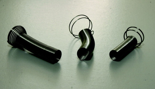
Recent publications has been advocating for increased dose in external beam radiotherapy (EBRT) for localized prostate cancer (PC) suggesting doses above 80 Gy Citation[1–3]. The use of 3D conformal radiotherapy or Intensity Modulated Radiotherapy (IMRT) techniques are necessary if radiation doses are to be escalated beyond conventional dose levels of 70 Gy without increasing morbidity Citation[4–7]. The use of a fiducial marker can lead to reduced margins around the clinical target volume (CTV) which may allow for further dose escalation Citation[8]. This can be obtained using various types of fiducial markers. The most common fiducial marker is gold grains, which are implanted into the prostate Citation[9–11]. A new alternative method is based on insertion of a commercial Ni-Ti prostate stent (Memokath™) Citation[12]. This stent however had an unacceptable risk of dislocation in patients whose urethral part of prostate (UP) is less than 40 mm. Consequently a new prostate stent (DS-I) was designed to reduce risk of dislocation. The DS-I stent was tested in another feasibility study. This study demonstrated that the DS-I stent also was not suitable due to risk of migration or patient discomfort (Unpublished data). Currently a new version of the Ni-Ti prostate stent, the DS-II, is undergoing clinical study. The three stent designs are shown in . Because the stent are made mainly of Ti with atomic number 22 good contrast is seen on x-ray images. This makes the marker suitable for x-ray positioning. Ti also has an electron density relative to water of 3.7. Consequently good contrast of the Ni Ti stent should be expected in MV beam as well. Finally the stent material is non magnetic and allow patients with inserted stent to be MR scanned. This new marker is an alternative to gold seed marker. The advantage of this new maker is that it allows routinely co-registration of MR and CT scan for treatment planning. It may be used for image guided radiotherapy using both kV and MV or combinations. Because of the size of the marker it can be perceived as a true 3D object. This allows for calculations of both translation and rotation. Finally the stent may relieve bladder outlet in patients with enlarged prostate and possibly prevent outlet obstruction during radiotherapy. The stent may be removed after treatment. The study is approved by the Ethical Committee and the Danish Medicines Agency. All participating patients give oral and sign informed consents. This paper will summarize data from the previous feasibility studies and give an introduction to the new DS-II stent investigated in the ongoing study.
Figure 1. Three different stent designs have been investigated. To the left is the Memokath, which was developed for treatment of benign prostate hyperplasia. In the middle is the DS-I stent. To the right is the DS-II stent, which currently is being investigated. All three designs are made of Ni Ti memory shape metal. Outer diameter of the stent is 7 mm and for the collar 14 mm fully expanded.
Materials and method
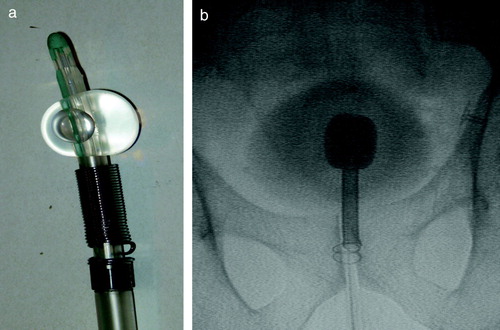
Patients participating in the study all have histological verified local or locally advanced prostate cancer (PC) and are referred to the department of oncology for curatively intended radiotherapy. Prostate work up is done in the department of urology before inclusion into the study. Patients are given neo adjuvant endocrine therapy with either GnRh analogues or anti-androgens for 3 months prior to radiotherapy. The stent is inserted two to three weeks before start of radiotherapy. Patients in whom UP is larger than 40 mm will have the Memokath™ stent inserted. Patient in whom UP is less than 40 mm will have the new DS-II stent inserted. Insertion is done at the department of oncology using an insertion kit with a Foley catheter and fluoroscopy as shown in . Locally urethral anaesthesia is obtained with lidocaine hydrochloride gel. Prophylactic antibiotics: Ciproxin 500 mg and analgetics Ibrufen 600 mg are administered in connection with the insertion. The DS-II stent come with a length of 40 mm and the Memokath at 65 mm. The work up diagnostic MR scan is used to measure the length of UP. Subsequently the length of each the stent is individually adapted using a cutter. The position of the external sphincter relative to the inferior medial part of the pubic bone is measured from the work up diagnostic MR scan as well. The ideal position of the stent is with the expandable collar lying just above the external sphincter. This correct position is ensured using fluoroscopy during the insertion. The catheter is inserted until the lower end of the stent is at the correct position above the inferior border of the pubic bone. Then the balloon on the Foley catheter is inflated with contrast media. Furthermore a 100 ml of diluted contrast media is injected into the bladder to visualize the bladder. The catheter is then gently pulled until the balloon touches the upper end of the stent at the bladder neck as shown in . With the stent in the correct position the collar of the stent is expanded using 50 ml 60°C hot water. The water is flushed through the insertion kit and over the stent. When heat is no longer applied to the stent expansion will stop and no further forces will be transferred to the surrounding tissue. With the stent released the balloon is emptied and the insertion kit with catheter is removed. The whole procedure takes approximately 6–8 minutes for the patient. Patients have to stay in the department until unaffected voiding function is secured, i.e. urine has been passed. One week after insertion a MR scan (1.5 or 3 Tesla, slice distance 3 mm T2-weighted) is performed. Images are acquired in the axial, sagital and coronal planes. Planning CT scan is done with the patient in the supine position with knee and feet fixation and image slice thickness is 2.5 mm end-end covering the whole scanned volume. Co-registration of the axial MR scan to the axial CT scan is performed using Eclipse® from Varian. Co-registration is automated using manually defined landmarks. Typically 5 landmarks are used. Three landmarks are defined on the stent. One at the cranial, middle and caudal end of the DS-II stent in both MR and CT image sets. Another two anatomical landmarks are defined. One anterior and one lateral to the stent, but as close to the prostate surface as possible. The Eclipse software calculates mean difference in the 3D position of the five landmarks and the point with maximum deviation. Mean difference should be less than or within 1–1.5 mm and the maximum deviation within or less than 2–3 mm. This was always achievable. Correct coincidence of the stent in the CT and MR images is always visually checked after automated registration. If not satisfactory, landmarks are re-adjusted and co-registration performed again until the stent coincide in CT and MR image sets. The clinical target volume (CTV) is defined as the prostate gland. In case of invasion or, according to Partin tables, high risk of invasion, CTV is defined as the prostate gland plus the proximal third part of the seminal vessels. In the current DS-II study CTV is outlined on CT, but information is also gained from using the co-registered MR images. PTV to CTV margin is 5 mm. Treatment planning in the current DS-II study is based on a technique with five conformal fields. Daily on-line positioning with the Brainlab Exactrac system is done, in each treatment session, before radiation delivery. For the first three sessions an additional set of orthogonal set of portal images are taken immediately after on-line positioning with the Exactrac system. The stent 3D position is determined from the portal dose images using a previously published method Citation[13]. Intra-fraction movements are determined using a second set of x-ray images and matching in Exactrac again. Any migration of the stent within the prostate is checked half way trough the radiotherapy course using a second MR scanning. The stent is removed three months after the last treatment session. Removal of the stent is done analogously to insertion. A flexible scope and a grasping forceps are used instead of the catheter. The stent is flushed with 5°C cold water. The metal become soft and the stent can be pulled out as a long tread. Impact of the stent insertion on patient's urinary symptoms is recorded prospectively using the International Prostate Symptom Score (IPSS) questionnaire. Patients are asked to fill out the IPSS questionnaire before insertion of the stent (Baseline), and subsequently 1–2 weeks after insertion around time of the planning CT scan, midway and at the end of radiotherapy, at stent removal and 1 month after removal. Prostate Specific Antigen (PSA) and scoring of treatment related adverse effects using the RTOG late morbidity score is done at regular follow-up.
Figure 2. a) The DS-II stent mounted on insertion kit and Foley catheter with balloon inflated. b) Flouroscopy image from insertion. The foley catheter s inflated with contrast media. The bladder is filled with diluted contrast media to give the contour of the bladder. The insertion kit has been pushed forward until the upper end of the stent touches the Foley catheter balloon. The distance from the lower end of the stent to the caudal part of the pubic has to match the measure from the diagnostic MR scan. The catheter has been flushed with hot water and the stent collar has expanded and locked the stent position in the prostate.
Results
At the present time 62 patients of 100 has been enrolled in the study. Of these patients 39 patients have received the DS-II stent, 18 the Memokath and 5 patients have left the study. Of the 39 DS-II stent one has migrated to the bladder. It should be noticed that only 27 patients have finished radiotherapy. One patient with UP less than 40 mm by mistake had a Memokath stent inserted. This stent also migrated to the bladder. This patient left the study. Data from the previous DS-I study in show that mean UP measured on the diagnostic MR scan taken before neo adjuvant endocrine therapy is 43.5 mm and mean UP measured on MR at time of insertion of the stent is 40.2 mm. If a paired t-test is performed p = 0.06 and thus non-significant. show an example of co-registration of MR scan to the planning CT after insertion of the stent. The mean and maximum error between the 3D position of the five landmarks were 1.25 mm and 1.86 mm respectively. In the previous DS-I study CTV was outlined independently based on CT and MR and compared. That study demonstrated deviations in CTV on CT and MR of more that 5 mm. Deviations larger than 5 mm were seen in anterior-posterior (AP), left-right (LR) and cranial-caudal (CC) directions as shown in . The previous DS-I study also showed a high risk of missing the cranial part of CTV, if CT alone was used for CTV delineation. Workaround for the daily on-line positioning using the Exactrac system was done changing the lookup table (LUT conversion of actual image pixel values to grayscale or color displayed on the monitor). The LUT is changed so only the most dense parts show up and using ROI to mask of bony structures as shown in . Masking out the bony structures before running the matching algorithm in Exactrac ensures a good match for the stent as shown in . Accuracy of the Exactrac positioning is checked independently using the orthogonal portal image pairs is shown in . Intra-fraction accuracy during treatment is determined using the extra set of Exactrac x-ray images after treatment has been delivered. Translations and rotations resulting from the second set of images represents movements that occurred between positioning using the first set of x-ray images. Translations in the three directions vertical (patient AP direction), lateral (patient LR direction) and longitudinal (patient CC direction) and rotations around the respective axes are shown in the polar plots in . Intra-fraction translation movements up to±3 mm are seen. Analogous shift in rotations between±2 degree are seen. But also rotations, outside the limitations of the Exactrac couch pitch:±2.5 degree and roll:±4 degree, as large as 15–20 degrees is observed. Very rapid organ movement was also demonstrated as shown in . This figure represents two images recorded with an electronic portal imaging device in lateral treatment fields. The images were taken during treatment in two different cases. Both images contain a record of a double stent. This is a result of the stent exhibiting rapid movement and rotation within the timeframe of recording a portal image (1–2 s).
Figure 3. Co-registered MR and CT scanning. Each image is divided in four quadrants. Counting clockwise the first and third quadrant is the MR image. The second and fourth is the CT image. The stent show up as a white structure on CT. Notice that partial volume effect increase the apparent size of the stent. On MR the stent show as a black (void signal) structure. The co-registration is shown in three planes a) axial b) sagital and c) coronal.
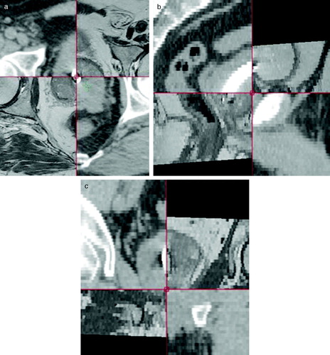
Figure 4. Data from the previous DS-I study where CTV was delineated independently on CT and MR scan of prostate. After delineation CT and MR scan were co-registered using the DS-I stent. Maximum difference between surface of CTV determined on CT and MR plotted versus length of intra prostate urethra. Dotted lines represent the 5 mm intended margin for IGRT treatment. Error bars are calculated as the maximum co-registration error divided by the square root of 3 assuming the equal error in all directions a) Anterior (white squares) and posterior (black squares), b) Left (white circles) Right (black circles), c) Cranial (white triangles) Caudal (black triangles).
Figure 5. Work around method for automated match of the DS-II stent in Exactrac. a) the DRR image constructed from the planning CT scan. The look up table (LUT) is changed to show the most dense parts only b) The combined DRR and x-ray image before match. Notice the difference in position of the stent. Red areas are bony structures that are masked out on the DRR image. c) The combined DRR and the x-ray image after matching. The small inserted window (spy-glass) demonstrate that the stent on DRR and x-ray now overlays.
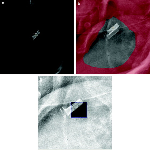
Figure 6. Polar plots of coordinates from second Exactrac match. Patients have been positioned before treatment using x-ray images and Exactrac. A second match is done, based on x-ray images taken after delivery of treatment fields. Data is from 747 treatment sessions in the first 20 patients. a) is the intra-fraction movement in the three patient axes Lateral, Longitudinal and vertical. b) is rotation around the same three axes Pitch, Roll and Yaw respectively.
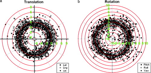
Figure 7. Images recorded with an electronic portal imaging device from two different patients. Timeframe for recording each image is approximately 1–2 s. Both images are seen to have a double image of the stent. This could only have been obtained if the stent has moved within the timeframe of recording the image.
Table I. Independent checks of Exactrac positioning. Data on deviation in stent position between portal image and DRR from planning CT scanning. Position of stent is calculated using 21 orthogonal portal images in seven patients. Portal images are taken immediately after positioning of the patient using the Exatrac system.
Discussion
This paper reports preliminary results on the use of a new Ni Ti prostate stent (DS-II) as fiducial marker for prostate. A previous study of a commercial Ni Ti prostate stent (Memokath™) demonstrated that this stent could only be used as fiducial marker if patient UP was larger than 40 mm. The diagnostic MR scan at the time of prostate work up is used to measure UP. Data from the previous DS-I study demonstrated that this measured UP is representative of UP at the time of insertion. The primary endpoint in the present study is the risk of migration of DS II stent to the bladder in patients with UP less than 40 mm. A long-term study of the use of Memokath in patients with benign hyperplasia has demonstrated a migration risk of 10% Citation[14]. Consequently this is taken as an acceptable risk of migration for the design in this study. A χ2 test is used with a type I error rate (alpha) of 0.05. Assuming that migration risk rate of 20% must be detected with a statistical strength of 80%, the study will require a population of 69 patients. Because two thirds of patients are expected to have an UP less than 40 mm the trial will require enrolment of approximately 100 patients and is expected to end in the beginning of 2009. Even though the study is still ongoing, it seems that the new DS-II stent does in fact have a small risk of migration to the bladder. Migration of the stent to the bladder was observed in both of the previous studies of Memokath and DS-I stent. No partial migration of the stent within the prostate within measuring accuracy (2–3 mm) was seen on CT in both the Memokath and DS-I study. CT has been replaced by MR scans in the present DS-II study, because MR is expected enable identification of possible partial migration with a higher accuracy than CT. No partial migration has been observed in the DS-II study so far. The Ni Ti prostate stent is suitable for MR-CT co-registration, giving good accuracy locally in region around the prostate. MR-CT co-registration was successfully done for all 62 patients enrolled so far. Co-registrations often demonstrate difference in both position and rotation of the prostate between the MR and CT scanning. This clearly demonstrated why co-registration on bony anatomy can not be used for prostate. Movement of the prostate during the acquisition of the MR scan was also seen to deteriorate image quality in several cases. This in turn may lead to reduced accuracy in the co-registration. Movements due to bowel activity could possibly be reduced using intra venous injection of hyoscyamine butylbromide (Buscopan). The importance of using MR or prostate delineation was clearly demonstrated in the previous DS-I study. Consequently, MR image sets can be used for CTV delineation with a higher degree of accuracy in all patients compared to use of CT only. This is important in the perspective of image guided radiotherapy where one may apply a small 5 mm CTV to PTV margins. Using only CT for delineation may lead to treatment of unnecessary large volumes, especially in the rectum, as demonstrated by others Citation[15]. Using only CT may also introduce a geographical miss at the cranial border of the prostate as shown in out previous DS-I study. The preliminary results from the current DS-II study demonstrated a clear learning curve for insertion of the stent. Ten of the first 24 patients needed a second stent insertion. Re-insertion was needed because the stent was not in the correct position in the prostate, or the stent became detached from the insertion kit before the stent was in the correct position. Passage of the external sphincter may be difficult because the lower part of the stent has an approximately 1 mm larger diameter. The stent may become detached from the insertion kit if the system is either rotated counter clockwise or if the insertion kit is manipulated or retracted too rough during insertion. Incorrectly positioned stent's were identified on the subsequent MR scan. In that case, the stent was removed and patients offered a new insertion. Three of the ten patients with incorrectly positioned stent chose gold markers instead and thus left this study. The remaining seven patients had a new stent inserted and completed their treatment. To ensure stent passage of the external sphincter, the procedure has now been changed. An additional measure is now taken on the diagnostic MR scan before insertion. This measure gives indication of the distance from the lower part of the pubic bone to the lower part of the stent (typically between 0 to 15 mm). Fluoroscopy is used check this distance during insertion. At present insertion is done routinely and with no further re-insertions needed so far. The whole insertion procedure takes between 6 and 10 minutes for the patient. Daily on-line positioning based on the work around for the Exactrac system is automated. The automated match is visually inspected in each case by the staff. In case of any mismatch, the staff performs a manual match. The orthogonal image pairs taken in the first three sessions give an independent validation of the positioning accuracy with Exactrac system. This validation demonstrates sub millimetre accuracy of the Exactrac system for positioning. During treatment time however, the good accuracy is degraded by intra-fraction movements. Each treatment session takes approximately 8–10 minutes. The intra-fraction movements of prostate, as observed in , are similar to the values observed by others Citation[16], Citation[17]. Movements may be identified due to either patient or prostate movement or a combination of both. A related problem identified is rotations outside the limitations of the Exactrac couch. These are rotations that cannot be accounted for by the Robotics system and they will appear in the second match as well as large movements. In retrospect, daily systematic large rotations are typically seen in patients who presented abnormal large rectal filling at the time of acquisition of planning CT. When patients are rescanned with a normal rectal filling, the systematic large rotations are reduced. Finally a few cases demonstrated very rapid (within 5 s) and large angle rotation (15–20°) of the prostate gland. These rotations have been observed on portal images from lateral treatment fields. They may be due to large volumes of bowel gas passing the rectum or involuntary tensions or spasms in the perineum musculature. Consequently further reduction in CTV to PTV margins will require online tracking of the fiducial marker. This may be possible with the DS-II stent as demonstrated in a previously published method based on gray scale morphology Citation[13]. The reported method is capable of finding the stent in kV and portal images within milliseconds. If the current DS-II stent study demonstrates that the stent is suitable as a fiducial marker there might be further advantages in using the stent. The stent provide the possibility of outlining the prostate part of urethra, which may be introduced as an organ of risk in treatment planning. Potentially IMRT can be used to reduce dose to the urethra. This will, however require that each IMRT treatment field can align dynamically with the stent using tracking during delivery. Such technique is not available today, but is theoretically possible. The DS-II stent also may also have further perspectives if specific areas in prostate are dose painted to higher doses. Currently feasibility studies of dose painting with IMRT boost up to between 90 and 95 Gray is under investigation Citation[18], Citation[19]. Such techniques are critically dependent on pinpoint accuracy of the lesions in question. The stent may also facilitate this.
Conclusion
The preliminary result of an on going clinical study of a Ni Ti prostate stent (DS-II), potentially a new fiducial marker for image guided radiotherapy, looks promising. The risk of migration is much lower compared to previous designs. The new marker can be used for CT-MR co-registration locally in the prostate and for automated daily online image guided radiotherapy in combination with the Exactrac system. Declaration of interest: The authors report no conflicts of interest. The authors alone are responsible for the content and writing of the paper.
References
- Cheung R, Tucker SL, Lee AK, de Crevoisier R, Dong L, Kamat A, et al. Dose-response characteristics of low- and intermediate-risk prostate cancer treated with external beam radiotherapy. Int J Radiat Oncol Biol Phys 2005; 61: 993–1002
- Kupelian P, Kuban D, Thames H, Levy L, Horwitz E, Martinez A, et al. Improved biochemical relapse-free survival with increased external radiation doses in patients with localized prostate cancer: The combined experience of nine institutions in patients treated in 1994 and 1995. Int J Radiat Oncol Biol Phys 2005; 61: 415–9
- Cheung MR. The need and prospect of individualized external beam radiotherapy dose escalation beyond 80 Gy to treat prostate cancer: In regard to Eade et al. (Int J Radiat Oncol Biol Phys 2007;68:682–9). Int J Radiat Oncol Biol Phys 2008; 70: 645–6
- Michalski JM, Purdy JA, Winter K, Roach M, III, Vijayakumar S, Sandler HM, et al. Preliminary report of toxicity following 3D radiation therapy for prostate cancer on 3DOG/RTOG 9406. Int J Radiat Oncol Biol Phys 2000; 46: 391–402
- Bey P, Carrie C, Beckendorf V, Ginestet C, Aletti P, Madelis G, et al. Dose escalation with 3D-CRT in prostate cancer: French study of dose escalation with conformal 3D radiotherapy in prostate cancer – Preliminary results. Int J Radiat Oncol Biol Phys 2000; 48: 513–7
- Boersma LJ, van den BM, Bruce AM, Shouman T, Gras L, te VA, et al. Estimation of the incidence of late bladder and rectum complications after high-dose (70–78 GY) conformal radiotherapy for prostate cancer, using dose-volume histograms. Int J Radiat Oncol Biol Phys 1998; 41: 83–92
- Teh BS, Mai WY, Grant WH, III, Chiu JK, Lu HH, Carpenter LS, et al. Intensity modulated radiotherapy (IMRT) decreases treatment-related morbidity and potentially enhances tumor control. Cancer Invest 2002; 20: 437–51
- Zhang M, Moiseenko V, Liu M, Craig T. Internal fiducial markers can assist dose escalation in treatment of prostate cancer: Result of organ motion simulations. Phys Med Biol 2006; 51: 269–85
- Crook JM, Raymond Y, Salhani D, Yang H, Esche B. Prostate motion during standard radiotherapy as assessed by fiducial markers. Radiother Oncol 1995; 37: 35–42
- Kitamura K, Shirato H, Shimizu S, Shinohara N, Harabayashi T, Shimizu T, et al. Registration accuracy and possible migration of internal fiducial gold marker implanted in prostate and liver treated with real-time tumor-tracking radiation therapy (RTRT). Radiother Oncol 2002; 62: 275–81
- Vigneault E, Pouliot J, Laverdiere J, Roy J, Dorion M. Electronic portal imaging device detection of radioopaque markers for the evaluation of prostate position during megavoltage irradiation: A clinical study. Int J Radiat Oncol Biol Phys 1997; 37: 205–12
- Carl J, Lund B, Larsen EH, Nielsen J. Feasibility study using a Ni-Ti stent and electronic portal imaging to localize the prostate during radiotherapy. Radiother Oncol 2006; 78: 199–206
- Carl J, Nielsen H, Nielsen J, Lund B, Larsen EH. Automated detection of a prostate Ni-Ti stent in electronic portal images. Med Phys 2006; 33: 4600–5
- Perry MJ, Roodhouse AJ, Gidlow AB, Spicer TG, Ellis BW. Thermo-expandable intraprostatic stents in bladder outlet obstruction: An 8-year study. BJU Int 2002; 90: 216–23
- Rasch C, Barillot I, Remeijer P, Touw A, van HM, Lebesque JV. Definition of the prostate in CT and MRI: A multi-observer study. Int J Radiat Oncol Biol Phys 1999; 43: 57–66
- Kotte AN, Hofman P, Lagendijk JJ, van VM, van der Heide UA. Intrafraction motion of the prostate during external-beam radiation therapy: Analysis of 427 patients with implanted fiducial markers. Int J Radiat Oncol Biol Phys 2007; 69: 419–25
- Linthout N, Verellen D, Tournel K, Reynders T, Duchateau M, Storme G. Assessment of secondary patient motion induced by automated couch movement during on-line 6 dimensional repositioning in prostate cancer treatment. Radiother Oncol 2007; 83: 168–74
- Singh AK, Guion P, Sears-Crouse N, Ullman K, Smith S, Albert PS, et al. Simultaneous integrated boost of biopsy proven, MRI defined dominant intra-prostatic lesions to 95 Gray with IMRT: Early results of a phase I NCI study. Radiat Oncol 2007; 2: 36
- van Lin EN, Futterer JJ, Heijmink SW, van d V, Hoffmann AL, van KP, et al. IMRT boost dose planning on dominant intraprostatic lesions: Gold marker-based three-dimensional fusion of CT with dynamic contrast-enhanced and 1H-spectroscopic MRI. Int J Radiat Oncol Biol Phys 2006; 65: 291–303