
 ?Mathematical formulae have been encoded as MathML and are displayed in this HTML version using MathJax in order to improve their display. Uncheck the box to turn MathJax off. This feature requires Javascript. Click on a formula to zoom.
ABSTRACT
This work investigates the melting behaviour of iron ore with calcium-based fluxes, including lime, limestone and basic oxygen furnace (BOF) steelmaking slag. With an aim to explore the potential kinetic benefits that can be obtained through the formation of a liquid medium on the overall productivity of HIsarna. A HT-CLSM was used to rapidly heat and observation the interface between a given pair of chosen materials in-situ. Through this method, the rate at which the reaction progressed and the possible disruptive phenomenon that may occur was observed directly. The molten interface of fluxed materials is compared against each other offering insight into relative dissolution rate. Each flux shows promise of increasing ore fluidity to a varying degree with limestone generating above a 60% liquid fraction in the 1400°C reaction temperature.
Introduction
Technological advancement and greater understanding of the steel production process have contributed greatly to the improvement in raw material use efficiency in the modern steel industry. However, the nature of the integrated steel plant is still reliant heavily on the use of coal, coke and electricity. The steel industry contributes to 6.7% of anthropogenic CO2 emissions globally [Citation1], which means that CO2 reduction in the steel industry cannot be ignored as a key step in meeting international climate control agreements. The European Union (EU) has made efforts with the aim of cutting the CO2 emissions of industry by 80–95% by 2050 [Citation2], however, the steel industry as a whole is estimated to be only 25–30% higher than the theoretical limit of energy consumption possible [Citation1]. Hence, to reach the EU CO2 emission reduction target, the European steel industry (and morally the wider community) must develop novel ironmaking processes to transform the industry.
HIsarna [Citation3–5], FINEX [Citation6] and COREX [Citation7] are all alternate ironmaking processes being developed to reduce CO2 emissions, replacing the currently main CO2 contributing step in production, the blast furnace (BF) ironmaking process. All three processes rely on the direct reduction or partial reduction of iron ore. In addition, direct reduced iron (DRI) is a key feedstock for electric arc furnace (EAF) practice in countries such as the U.S.A. and Turkey where there is an abundance of natural gas. Direct reduction requires a reductive gas atmosphere, usually CO from coal or natural gas to reduce the ore to iron. Pre-reduction partially reduces the ore before complete reduction of the ore in a hearth or smelting vessel. Reduction of the ore consists of multi-steps shown in Equations (1)—(3).
(1)
(1)
(2)
(2)
(3)
(3) The reduction reactions in these novel ironmaking processes are conducted in solid-state. As in most cases, solid-state reactions are kinetically slower than liquid state reactions and are therefore potentially limiting to the iron production rate if these technologies are to be widely adopted. The rate of this reaction can either be increased through optimising conditions such as temperature, pressure and variant in iron source or through creating intermediate active species to encourage a fundamental step change in the rate-limiting step of the reaction.
Flux from a metallurgical standing is a chemical cleaning agent or purifying agent, which is used in both extraction and joining of metals. A flux material added during smelting is bound to unwanted minerals to help remove them, forming slags [Citation8]. As this is an important part of the iron-making and steelmaking processes, it has seen a large level of interest from the research community. Specifically, on the capability of CaO fluxes as this is an effective flux and already implemented in steelmaking processes due to its price, availability and effectiveness at removing key impurities such as silica and phosphorus [Citation9].
Adding flux in HIsarna in the cyclone converter furnace (CCF – the location of solid-state pre-reduction in the process) with the addition of iron ore offers the normal production advantages such as removal of SiO2 from the ore, but also offers early fluxing opportunity. Due to the mixing mechanics, the iron may form an early liquid slag inside the CCF, which should aid the reduction of potential accretions in the furnace, as the lower melting point will stop the solidification of the material at cool spots of the furnace. These can cause significant processing problems as pathways can be blocked, for instance, the most vital being that between the CCF and the smelting reduction vessel (SRV – the location of carbon fuel injection and full conversion to liquid hot metal).
This paper will investigate interactions between CaO-bearing fluxes and iron oxide in iron ore. Lime, limestone and readily available BOF slag present a well-established set of CaO containing derivatives due to their current use and availability on a steel plant and the cross comparisons of cleaner and heavily mixed substances. The focus of this study is on each material’s ability to encourage the presence of a liquid state within the ore at short interaction times. The phase diagram for CaO and FeOx can be found in the slag atlas based on the work from Phillips and Muan. [Citation10,Citation11] Shows that between 0 and 40% CaO has a strong influence on reducing the melting point of the iron species from around 1600°C to 1205°C at the eutectic. [Citation10] The presence of a liquid species as discussed above has the potential to unlock the rate of reduction, with the mass transfer of species such as oxygen, phosphorus, and sulphur being orders of magnitude higher in liquid phase compared to solid diffusion.
Experimental method
Samples of iron ore were placed in contact with the chosen fluxing agent and heated to the designed temperature (1350–1450°C) to begin the reaction between the materials. During heating, the reaction between iron ore and fluxing agent is viewed in-situ using a High-Temperature Confocal Scanning Laser Microscope (HT-CSLM), and subsequently interrogated using post-analysis techniques such as Scanning Electron Microscopy (SEM) and Energy dispersive spectroscopy (EDS). The performance of each flux will be compared by looking at the liquid phase of the composition of the melt and the effects of liquid fraction and reaction mechanism discussed as to their potential of effect on reduction rates.
Materials
The iron ore, limestone and BOF slag were all sourced from Tata Steel IJmuiden Steel plant and compositions were provided. The iron ore used un-sintered, un-pelleted and dried with 66% of iron content classified as a high–grade ore/high iron content. The lime used was purchased from Sigma-Aldrich, regent grade with a purity of 99%. The limestone contained 55% CaO and 37% CO2 which is assumed to be combined in the form CaCO3. The lime used was purchased from Sigma-Aldrich, regent grade with a purity of 99%. The composition of all the materials used is given in .
Table 1. All materials used in the experiments with the composition of the materials in wt-%.
HT-CSLM
The HT-CSLM is an in-situ observation tool consisting of a gold-coated elliptical chamber positioned below a UV imaging laser. The chamber has the ability to reach 1700°C at the heating rate of up to 700°C min−1 and cooling rates of up to 3000°C min−1 (in the higher temperature range). Within the chamber, a halogen bulb is located in one focal point, which emits IR radiation. The IR radiation is subsequently focused on to the sample which is positioned in the second focal point of the ellipse. The sample sits on an instrumented alumina stage, where an R-type thermocouple is threaded through and attached to the bottom of a platinum ring – the location the sample sits upon. The atmosphere in the chamber can be controlled through the rotary vacuum pump extraction and a high-purity gas feed. Images of the confocal are presented in [Citation12].
Figure 1. HT-CSLM (A) shows an image of the entire HT-CLSM with the tensile compression stage (B) Show the interior of the High-temperature chamber.
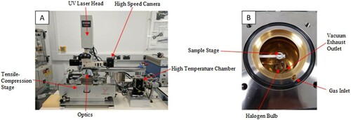
The furnace works in-situ with a UV laser microscope, which avoids image interference from the IR radiation from the bulb and hot sample. The microscope sits above the chamber and can look at the sample through a quartz window at the top of the chamber. The optics within a confocal microscope are designed to give a very narrow depth field of view, allowing the equipment to image surface roughness and texture in high detail.
Experimental procedure
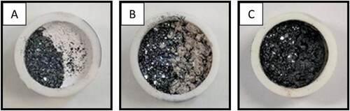
An alumina crucible was half filled with iron ore and half filled with fluxing agent side by side (). The material was compressed in the crucible so that there is a defined interface between the two materials. The sample was then heated to 1350°C, 1400°C and 1450°C at 500°C min−1 and held for 60 s before being rapidly quenched. The experiments were recorded at 15 fps. The experiments were conducted in an air atmosphere at the appropriate partial pressure of oxygen ensuring no occurrence of passive diffusion-led reduction in the iron ore during the experiment.
Figure 2. The crucible samples before use the experiments. (A) Crucible of iron ore and lime. (B) Crucible of iron ore and limestone. (C) Crucible of iron ore and slag.
The quenched sample was mounted in epoxy resin and polished to a flat surface using SiC grinding pads incrementally increasing the grit from 800 p through to 1500 p. The sample was polished with oil-based diamond suspensions with particle sizes from 9 μm, 3 μm to 1 μm in turn. This routine was done without the use of water so as not to effect the anhydrous CaO in the samples. This polishing routine gave a clean and flat surface ready for SEM imaging and EDS elemental analysis.
FEG-SEM and EDS
The scanning electron microscope use (SEM) was the JEOL 7800F model, a FEG-SEM equipped with an oxford instruments EDS detector. This instrument allowed for rapid pump down of samples after removal from a desiccator limiting interaction with ambient moisture.
Results
A high-grade iron ore (62% Fe) has been placed into alumina crucible along with three chosen fluxing agents. The two materials have been observed in-situ while heated to 1400°C and held for 60 s. The quenched samples have then been cut, polished and investigated via SEM and EDS. Each material pair is presented below with brief comments on key observations on how the materials have interacted.
Lime – iron ore
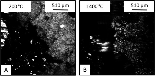
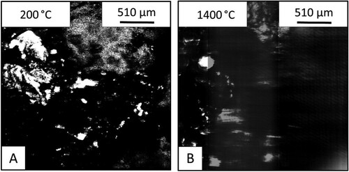
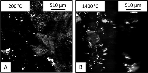
shows the images from the HT-CSLM of the lime (CaO) – iron ore samples. Image A shows the sample before the heating and image B shows the sample after holding at 1400°C for 60 s. At 200°C the two materials have a distinct interface between the lime on the right and the ore on the left. At 1400°C the two materials appear significantly changed, with the ore on the left showing evidence of melting – depicted by the bright section near the centre of the image (at the original sample interface). This section was seen to be fluid and appears brighter due to the flat nature of the liquid surface allowing for a larger section of the field of view to be in focus at a single time point.
Figure 3. HT-CSLM images of lime-iron ore reaction before (A) and after (B) heating.
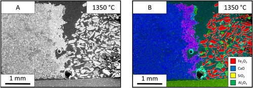
(A) displays SEM images of the sample with the lime on the left and ore on the right. The lime is seen to be unaffected by the heat and seems almost homogenous. The bulk of ore is also similar to that before the heat treatment, with the particles appearing angular and discrete showing no signs of fully melting. The images also show that there is an interface region between the two materials, which has undergone significant mixing. The interface is clearer in the EDS mapping ((B)) where the purple region shows the elemental mixing of the two main species (Ca and Fe). The liquidus interface which has formed during the experiment appears to strongly adhere/wet the bulk lime phase preferentially.
Figure 4. Images from the 1350°C lime sample. (A) Electron image of the lime sample. (B) EDS map of the lime electron image.
The reaction of lime and iron ore was studied further by holding the reaction at different temperatures of 1350°C (), 1400°C () and 1450°C (). The SEM images allowed for the measurement of liquid fraction over the three temperatures. These were measured at 16%, 32% and 41%, respectively. The increased temperature sped up the reaction and shows the progression of the reaction seen through the holding times. The molten area interface between the two materials is more defined and consistent at the higher temperatures. At 1350°C, the interface is thin and the blue calcium is dispersed throughout the molten phase. While the sample after holding at 1400°C for 60 s is thicker in width and shows less dispersion of the pure CaO flux solution interface. The progression of the reaction pathway can be viewed between these three samples with the higher temperatures showing further progression of mixing.
Figure 5. Images from the 1400°C lime sample. (A) Electron image of the lime sample. (B) EDS map of the lime electron image.
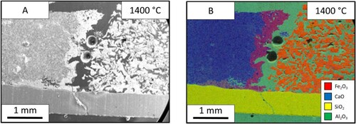
Figure 6. Images from the 1450°C lime sample. (A) Electron image of the lime sample. (B) EDS map of the lime electron image.
Limestone – iron ore
The HT-CSLM images in shows that at 200°C the limestone (right) – iron ore (left) sample. Owing to the larger particle size of the limestone, the image is rougher on the surface and is not as clear as the finer particle size lime sample (). After heating to 1400°C the image shows evidence of liquid in the sample seen in the white areas in the iron ore side of the interface.
Figure 7. Images from the HT-CSLM of the limestone – iron ore sample of (A) before and (B) after heating.
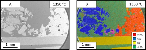
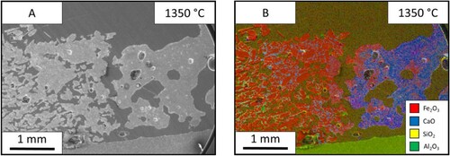
The SEM images of this sample ((A)) show that the limestone had a substantial effect on the appearance of the ore after heating. Unlike the ore in the lime samples, the ore is more homogeneous with less distinct particles and more connected mass. The bulk limestone in the left of the image seems to look like the material before the experiment. The limestone particles near the ore interface; shown clearly in (B), have an external reaction layer. These particles surrounded by reacting material are the closest this sample came to forming a continuous/defined reaction interface between the two materials.
Figure 8. Images from the limestone (left) – iron ore (right) sample after holding 1350°C for 60 s: (A) SEM image and EDS mapping of the limestone-iron ore sample.
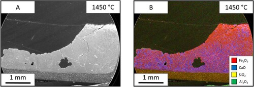
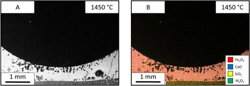
The test was carried out at three temperatures of 1350°C (), 1400°C () and 1450°C (), and the liquid fraction was measured to be 26%, 64% and 99% respectively. In the 1350°C image, the ore is one homogeneous phase, however; there is a dispersion of iron and calcium throughout. Between the two interfaces, the limestone particles can be seen mid reaction as the particles have a coating of CaO-FeO solution. The 1450°C sample shoes a single phase.
Figure 9. Images from the limestone (left) – iron ore (right) sample after holding at 1400°C for 60 s: (A) SEM image, and (B) EDS mapping of the sample.

Figure 10. Images from the limestone-iron ore sample after holding at 1450°C for 60 s: (A) SEM image and (B) EDS mapping of the sample.
BOF slag – iron ore
shows the samples of iron ore and BOF slag as observed via HT-CSLM. The slag (right) is less bright than the fluxing phase in the previous samples but the interface is still clearly visible before the experiment. The Images taken after the heating show that unlike the previous samples, molten material is present throughout the crucible, not only in the ore side or at the interface.
Figure 11. Images from the HT-CSLM of the BOF slag – iron ore sample: (A) before and (B) after heating.
The SEM results from the slag sample are shown in . The electron image shows that the iron ore (left) still displays similar properties to an un-molten sample, as there are small separated particles like that found in the lime sample. However, there is no linier reaction interface between the two phases as seen in the lime sample. At the interface, the sample appears as an exaggerated form of the limestone sample, with particles surrounded by reacting material ((B)). In addition, the slag seems to be fully molten, which is to be expected due to its theoretical melting point, displaying a greater increase of iron content throughout the bulk phase compared to the other two fluxing materials.
Figure 12. Images from the BOF slag-iron ore sample after holding at 1350°C for 60 s: (A) SEM image and (B) EDS mapping of the BOF slag – iron ore sample.
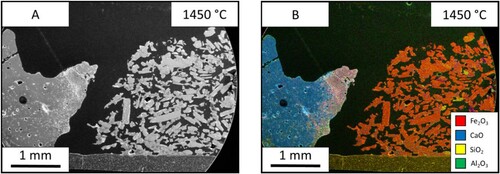
The test was done at three different temperatures of 1350 °C (), 1400°C () and 1450°C () and have a liquid fraction of 23%, 34% and 100%, respectively. In the 1350°C slag, the sample shows that the iron ore can still be seen as individual particles however, they are suspended in a matrix of the slag. The slag itself is molten, however, it seems to have no reaction with the iron ore despite flowing through the material. The 1450°C sample shows that there is one homogeneous structure. The sample has been fully molten due to the meniscus shape of the sample.
Figure 13. Images from the 1400°C slag samples. (A) electron image of the BOF slag sample, (B) EDS map of the BOF slag electron image.
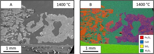
Figure 14. Images from the 1450°C slag samples. (A) electron image of the BOF slag sample, (B) EDS map of the BOF slag electron image.
Discussion
Fluxing material difference
By segmenting molten material from the SEM images and measuring the surface area fraction with image analysis software, the percentage of iron ore in molten state has been calculated for each material pairing. The lime and BOF slag have similar levels of molten iron ore at 1400°C with results of 32% and 34%, respectively, while limestone had a significantly higher result of 64% liquid material.
Lime and BOF slag gained very similar liquid percentage however, the nature of the liquid fraction and its dispersion throughout the samples differ greatly. The lime-ore sample has a thick molten area at the interface connected to the lime. The BOF slag-ore sample shows no defined molten interface, as compared to that which was observed, in the lime-ore sample, and the molten section is spread throughout the iron ore in the sample. Furthermore, the lime in the sample is still solid and tightly packed whereas the BOF slag has fully melted into a continuous medium.
Owing to the solid phase reaction between the lime and iron ore, the reaction has a defined reaction zone, which is limited by the size of the contact interface. The reaction can only progress through this liner interface, and perpetuate through the dissolution of the materials into either side of this experimentally size determined reaction interface. This reaction interface width would continue to grow in depth if the experiment was conducted for longer period, but the reaction area would remain approximately the same.
The BOF-iron ore slag sample has a different reaction path due to the lower melting of the fluxing agent. Being molten at experimental temperatures the material appears to have permeated through the iron ore matrix, resulting in an exponential growth of the liquid reaction interfacial area. Although at the time point these experiments were predetermined to stop at, the liquid fraction is similar between lime-ore and BOF slag-ore samples, the extensive mixing and more complex nature of the interface topology developed by the BOF slag-iron ore reaction preludes a higher interfacial area and faster interface development through the bulk phase.
The limestone sample outperformed both lime and BOF slag for liquid fraction development. The limestone follows similar conditions to the lime, however, it benefits from two key differences. The first is that limestone undergoes calcination at 900°C to form the CaO actually utilised in the reaction, the calcination reaction is shown in Equation (4) [Citation13]. The literature has previously stated that limestone calcination results in newly formed CaO which has a higher reaction activity than aged lime in processes such as lime dissolution in slag [Citation14]. Second the limestone used is of larger particle size than the lime, as such when a particle begins to flux the connectivity of the fluxing agent is effectively larger, allowing for wetting phenomena to surround or ‘drag’ the material into the molten pool.
(4)
(4) Because of the sample size usable in the HT-CSLM, the actual effect of these materials on reduction kinetics is beyond the scope of this paper as there is not enough material for any quantitative analyses to be conducted. However, the mechanisms and influencing physical factors of three key metallurgical fluxing agents have been observed and discussed as to their expected effect on reduction. This work will be combined with larger bulk furnace trials and reductive environments in the near future, enabling a direct assessment on reduction performance under fluxing effects. From the above, limestone and BOF slag could both be considered potentially useful materials to add into gas reduction processes of iron ore. The higher-order fluxing rate of limestone presents a key case for increasing liquid fraction. However, the permeation of liquid BOS slag through the bulk ore at the reaction temperatures presents a potentially exploitable fluxing pathway which will only be exacerbated by the large volume/bulk production facilities used in ironmaking (as opposed to the lime and limestone which develop a liquid reaction interface purely on a pre-determined engineered interfacial area).
Based on the shrinking core model the reduction mechanism of iron ore [Citation15,Citation16] can be broken down into several stages including:
Mass transfer of reductive species in the gas phase
Diffusion of reaction species and products across the gas boundary layer
Diffusion of CO through the partially reduced ore particle
Reaction at the reduction frontier
Diffusion of CO2 away from the reaction interface
To begin with, due to the ultra-high temperature of the system and the high Gibbs free energy, it is fair to assume that the reaction at the reduction frontier is unlikely to be reduction rate limiting. In addition, the ultrasonic gas turbulence and abundant supply of reductive gas species leads the assumption that mass transfer in the gas phase is also non-rate limiting. This leaves diffusion through the gas boundary layer and transport of reduction reactants/products through the reduced layer of the ore particle as possible rate-limiting steps.
Boundary layer diffusion can be qualitatively interrogated through calculation of the dimensionless Sherwood number expressed in Equation (5), using the same form as the Ranz-Marshall Correlation for heat transfer to a sphere, substitution of the Prandtl number for the Schmitt number (defined as the ratio of momentum diffusivity and mass diffusivity) (Equation (6)) gives an analogous form to appreciate the controlling factors on this variable with relation to other transport phenomena:
(5)
(5)
(6)
(6) Both the Reynolds and Schmitt numbers are calculated from variables including matter viscosity, density, diffusivity, distance and velocity. The controlling factor for most of these variables is temperature, a process parameter that is more technologically defined/restricted in industrial reduction processes rather than scientifically targetable.
As a result, this leaves diffusion of reactants and products through the iron ore particles as the main way of influencing reduction kinetics. Fluxing/formation of a liquid phase within the process is likely to have two opposing contributions to this:
Formations of liquid/a continuous medium reduces surface area of the iron ore and thus increases the physical reaction pathway from the bulk gas to the unreacted material inside ore particles
Diffusion/transport kinetics are much faster in liquid phase than in solid, not only due to high diffusion coefficients but also convection stirring within the liquid medium.
Temperature
The temperature of the test has shown an increase of the liquid fraction in all three of the fluxing agents but to differing degrees of influence. The temperature has the effect of speeding up reactions and giving more energy to the reactants. This determined that the interaction is governed by the diffusion rates of the ore into the flux. If the reaction rate was controlled solely by the size of the interface then there would be no difference as the temperature changes.
The lime samples show this by the sharp increase of fluid fraction between 1350°C and 1400°C from 16% to 32% and another increase at 1450°C to 41%. This is due to the diffusion rate increasing in line with the greater thermal energy within the system.
The limestone samples reacted more at the higher temperature with the highest temperature samples becoming molten. At the temperatures 1350°C and 1400°C when compared to the CaO samples this can be explained by the higher liquid fraction created around the core of the shrinking core. This liquidous fraction material increases and intern speeds up the rate of interaction between the materials due to the diffusion transforming from solid to solid to liquid to solid thus generating a runaway effect on the rate of interaction.
The BOF slag sample suffers in terms of reaction rate due to the melting point of the slag being lower than the product of the iron ore and flux. This means that the liquid to solid interaction is reached at lower temperatures. In the highest temperature sample, the crucible shows a full miscues showing a full homogenous matrix of the ore and the slag combined. The lower temperatures have a molten slag and a solid matrix of iron ore. The temperature is important in this reaction in order to reach a critical phase reaction barrier to enable the process to take place. Once these boundaries are met the slag can be seen as a valid option as a fluxing reagent.
Conclusion
The mechanistic interactions between iron ore and three common metallurgical fluxing agents (CaO, CaCO3 and BOF slag) have been observed in-situ at temperatures of 1350, 1400 and 1450oC and through ex-situ electron microscopy. The aim of the experiments was to begin to uncover the potential benefit that the co-injection of the reactants could provide to the reduction or pre-reduction of iron ore within the low carbon ironmaking technology HIsarna. In addition, the specific use of BOF slag offers a recycling and metallic content reclamation potential within integrated steelworks improving overall yield.
Experimentally the fluxes can be ranked on liquid fraction formed over the same defined reaction period as limestone >> slag ≥ lime. The limestone results show that newly formed CaO reactant species offer increased fluxing reaction kinetics.
Despite this, the use of a fluxing agent which is operating above its melting point (BOF slag) presents a technological advantage when scale-up is considered for industrial application. Liquid fluxes will mix faster and more consistently with the ore, allowing for the formation of an overall larger reaction interface with greater growth potential throughout the bulk process.
Acknowledgements
JW appreciates the Ph.D. scholarship provided by WMG, University of Warwick, and support from Tata Steel IJmuiden for providing materials and discussions. ZL acknowledges EPSRC for funding under the grant number EP/N011368/1 (EPSRC Fellowship).
Disclosure statement
No potential conflict of interest was reported by the author(s).
Additional information
Funding
References
- Sridhar S, Li Z. Can there be a sunrise in steel town ? Ironmak Steelmak. 2016;43:642–649.
- European Commission. Communication from the Commission: a roadmap for moving to a competitive low carbon economy in 2050. COM(2011) 112 final, 112. 2011.
- Meijer K, Guenther C, Dry RJ.. HIsarna pilot plant project June Düsseldorf Germany. Energy Efficiency and CO2 Reduction in the Steel Industry; 2011.
- Jahanshahi S, Mathieson JG, Reimink H. Low emission steelmaking. J Sustain. Metall. 2016;2:185–190.
- Meijer K, Treadgold C, Zeilstra C, et al. HIsarna Experimental Campaigns B and C. Luxembourg: European Commission; 2015.
- Babich A, Senk D. Chapter 12 – coal use in iron and steel metallurgy. In: Osborne D, editor. The coal handbook: towards cleaner production. Aachen, Germany: Woodhead; 2013. 2, p. 267–311.
- Technology, V. A. I. I. COREX® : Efficient and environmentally friendly smelting reduction. Linz, Austria: Primemetal Technologies Austria GmbH; 2015. p. 16.
- Kokal HR, Ranade MG. Metallurgical uses fluxes for metallurgy. Ind Miner Rocks. 1994;15:661–675.
- Tayeb MA, Spooner S. Phosphorus : the noose of sustainability and renewability in steelmaking. JOM. 2014;66:1565–1571.
- Kowalski M, Spencer PJ, Neuschütz D. 3.2.2 binary oxide system. In: Eisenhuttenleute VD, editor. Slag atlas. Düsseldorf, Germany: Verlag Stahleisen mbH; 1995. p. 57–58.
- Phillips B, Muan A. Phase equilibria in the system CaO-iron oxide- SiO2 in air. J Am Ceram Soc. 1959;42:413–423.
- Spooner S. Quantifying the transient interfacial area during slag-metal reactions. Coventry: University of Warwick; 2017.
- Kumar GS, Ramakrishnan A, Hung Y-T. Lime calcination. In: Wang LK, Hung Y-T, Shammas NK, editors. Handbook of environmental engineering. Totowa (NJ): Humana Press; 2007. p. 611–633.
- Glasson DR. Reactivity of lime and related oxides. I. Production of calcium oxide. J Appl Chem. 1958;8:793–797.
- McKewan WM. Kinetics of iron ore reduction. Trans Am Inst Min Metall Eng. 1958;212:791–793.
- Qu Y. Experimental study of the melting and reduction behaviour of ore used in the HIsarna process [PhD thesis]. Delft University of Technology; 2013.