Abstract
Accurate measurements of streamflow velocity and discharge can be challenging due to the technical nature of the instruments and often-associated high cost. Velocity-head rods measure the head difference in water flowing around an obstacle (i.e. the head rod) and use hydraulic theory to estimate water velocity. This article presents the construction and testing of a modified transparent velocity-head rod (mTVHR). Approximately 2400 pairs of mTVHR and SonTek FlowTracker (FT, acoustic Doppler) measurements were made on 31 dates, by seven operators at 14 sites. This data set allowed for the development of a calibrated relationship for velocity, for the investigation of accuracy among multiple users and for the definition of stream conditions where mTVHR use is appropriate. While there was evidence of differences between users for measurements of velocity-head and water depth, these differences were small and did not greatly influence discharge estimates derived using the instrument. While statistical analysis determined a minimum measureable velocity-head value of 1 mm, field experience with the instrument indicates the mTVHR should be used to measure velocity-head values greater than 2 mm. The maximum water depth recommended is approximately 0.75 m due to the 1-m height of the instrument and the difficulty of safe operation at moderately fast streamflow velocities. Turbulent streams and/or streams with large bed materials are not appropriate for use of the mTVHR due to rapid velocity-head fluctuations. The mTVHR is an accurate instrument for measuring streamflow velocity, depth and discharge. In addition, its ease of use, low cost (< CAN $100), and durability make it an attractive option for streamflow measurement.
Il est souvent difficile de faire des mesures précises de la vitesse du débit d’eau, en raison de la nature technique des instruments et des coûts élevés souvent associés avec cette mesure. Les tiges pour mesurer la hauteur dynamique mesurent la différence du débit d’eau coulant autour de la tige, et utilise la théorie hydraulique pour estimer la vitesse de l'eau. Cet article présente le travail fait pour la construction et les essais d'une tige de la hauteur dynamique transparente modifiée, dite “modified transparent velocity-head rod” ou mTVHR. Environ 2400 paires de mesures, à l’aide du mTVHR et d’une sonde acoustique Doppler SonTek, ont été effectuées sur une période de 31 jours, à 14 sites, par sept opérateurs. Cet ensemble de données, verifier par l’enquête de précision auprès de multiples utilisateurs, a permit le développement d'une relation calibré pour la vitesse, et pour la définition des conditions pour les courants d’eau où l’utilisation du mTVHR est approprié. Bien que l’enquête de précision a révélé des différences entre les utilisateurs pour les mesures de profondeur et de la hauteur dynamique, celles-ci étaient faibles et n'ont pas grandement influencé les estimations obtenues à l'aide de l'instrument. Bien que l'analyse statistique a déterminé que la valeur minimale de la hauteur dynamique devrait être dans l’ordre de 1 mm, l’expérience sur le terrain avec l'instrument indique que le mTVHR doit être utilisé pour mesurer la hauteur dynamique pour toute valeur supérieure à 2 mm. La profondeur d'eau maximale recommandée est environ 0,75 m en raison de la hauteur de l'instrument, qui est de 1 m, et de la difficulté à prendre des mesures en toute sécurité à des vitesses de débit modérément rapide. Les cours d’eau où le courant est turbulent, ou ceux avec des matériaux de fonds assez large, ne sont pas appropriés pour l'utilisation du mTVHR, en raison des fluctuations rapides de la hauteur dynamique. Le mTVHR est un instrument précis pour mesurer la vitesse du débit d’eau et la profonde du courant. C’est aussi un instrument facile à utiliser, dont le faible coût (< CAN $100) et la durabilité, en font une option intéressante pour la mesure du débit d'eau.
Introduction
Natural resource management and water-related monitoring programs often require accurate streamflow data. Precise and accurate measurements of stream depth and velocity, however, can be difficult to obtain due to the challenging nature of some methods and, often, equipment expense. The velocity-head rod (VHR; Wilm and Storey Citation1944) and similar instruments, such as the velocity-head tube (Ciborowski Citation1991) and the transparent velocity-head rod (TVHR, Fonstad et al. Citation2005), are simple, inexpensive instruments designed for measuring stream velocities and depths. The VHR approach is based on the principle that the height of water (velocity-head) hitting an obstruction is equal to the kinetic energy of the water flowing past the obstruction (Wilm and Storey Citation1944; Fonstad et al. Citation2005). The faster water flows against an object held perpendicular to the flow, the higher the water level (velocity-head) will be on the upstream side. Velocity-head is calculated as the difference between the elevated upstream and the unimpeded water depth. The method, based on the Bernoulli equation, assumes that the velocity-head (potential energy) is equal to the kinetic energy of the flowing water, there are no energy losses due to effects of friction or heating around the instrument, there is steady flow and a constant fluid density and the points being measured are along the same streamline (Gordon et al. Citation2004). It is uncommon to meet all of these assumptions in natural streams, meaning instrument-specific calibration and careful site selection are critical in collecting accurate data.
Early users of the VHR method relied on a theoretical equation (Equation 1) to convert velocity-head measurements into velocity estimates (Wilm and Storey Citation1944; Drost Citation1963; Heede Citation1974; Carufel Citation1980; Harding et al. Citation2009; Environment Canada Citation2012) where v = velocity (m s−1), g = acceleration due to gravity (9.8 m s−2) and h = the velocity-head (m) as measured by the respective instrument(1)
Fonstad et al. (Citation2005) modified the original VHR making it transparent (i.e. transparent velocity-head rod or TVHR), a refinement that allowed for consistency in measuring the up- and downstream water levels by eliminating the need for the operator to rotate the instrument or bend around it to collect data. Fonstad et al. (Citation2005) tested Equation (1) and found that it consistently overestimated velocity. To correct for this overestimation, Fonstad et al. (Citation2005) developed an empirical, instrument-specific relationship based on 40 measurements collected on the same day, from a single stream, less than 1 m in depth (Equation 2). (2)
For the comparison against the TVHR, Fonstad et al. (Citation2005) averaged two velocity measurements (using 0.2/0.8 m depth method) taken with a Price AA current meter. Velocity-head values in Fonstad et al.’s study ranged from 10 to 110 mm, which corresponds to velocities of roughly 0.2–1.0 m s−1. Fonstad et al. (Citation2005) reported that TVHR velocity results were “typically precise within 5%”. The technique derived by Fonstad et al. (Citation2005) eliminated the error associated with rotating the rod, but sacrificed obtaining a water depth reading, and therefore did not calculate discharges.
Following the instrument design specifications published in Fonstad et al. (Citation2005), two TVHRs were constructed by this study’s authors to evaluate the instrument for use in operational resource management and educational settings in British Columbia. Preliminary tests of the TVHR uncovered difficulties. The thin design (3.2 mm) of the TVHR led to excessive bending of the instrument in deep water under moderate to fast velocities. The transparent design also resulted in image refraction and potential for errors when reading the velocity-head value though the transparent rod. As a result, a modified version of the Fonstad et al. (Citation2005) design (herein called mTVHR) was produced by this study’s authors to address issues of instrument bending and refraction. These changes were designed to increase the reproducibility and accuracy of velocity-head measurements. The mTVHR method was tested and calibrated over a 3-year period, across a range of streams on southern Vancouver Island using multiple operators.
The specific objectives of this study were to:
| (1) | Design and construct a useable mTVHR; | ||||
| (2) | Calibrate the mTVHR across a range of streams on southern Vancouver Island; | ||||
| (3) | Compare operator performance between multiple mTVHR users; | ||||
| (4) | Evaluate performance of the mTVHR in estimating stream discharge; and | ||||
| (5) | Determine the depth, velocity and channel conditions under which the mTVHR may be confidently applied. | ||||
Methods
Initial tests of the TVHR
Initial tests of the Fonstad et al. (Citation2005) version of the TVHR revealed two key issues. Water velocities greater than 0.5 m s−1 caused excessive bending of the instrument. As a result, the rulers that were glued to the TVHR came off after approximately 60 measurements, and it was surmised that the bending of the instrument was possibly affecting velocity-head measurements. Even though the TVHR was thin (3.2 mm), it was apparent that refraction through the TVHR was potentially influencing the precision and accuracy of velocity-head measurements. It was observed that users recorded different velocity-head values depending on their view angle and height to the instrument. Viewing angle changes and subsequent image shifting were hard to control for in the TVHR as there was no way to standardize the view height/angle between measurements or among users.
mTVHR instrument design and construction
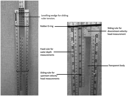
To address the above issues, the authors produced a modified version of the TVHR, the mTVHR, that was constructed with thicker material (12 mm, 0.5 inch Plexiglas) while keeping the same length and width (9.85 cm × 100 cm) dimensions. Aluminum metre sticks were riveted to the downstream side of the instrument to ensure they did not detach during use and periodic flexing. To address refraction issues and minimize potential error due to variable viewing angles and observer heights, two additional aluminum metre sticks were added to the instrument and secured with three rubber O-rings (Figure ). Tension on the added metre sticks was achieved by using a door-leveling wedge (Figure ). The modification objective was to use commonly available and inexpensive materials. Three identical mTVHR prototypes were constructed and randomly used throughout the subsequent data collection. The production costs of the mTVHR were less than CAN $100 per unit.
Instruments, field sites and summary of data collection
A SonTek FlowTracker handheld Acoustic Doppler Velocimeter ADV (FT) and topset rod (including a SonTek FlowTracker S-Bend adaptor mount that included a horizontal offset) were used to collect reference water velocities and depths. The FT uses sound (acoustic Doppler technology) to measure water velocity. The FT was selected as the comparative standard over the AA-current meter for the following reasons:
| (1) | The FT can be used in shallower water depths than an AA unit; | ||||
| (2) | The resolution and accuracy of FT at slow water velocities is better than a typical AA unit (i.e. 0.001 m s−1 FT compared to 0.030 m s−1 for AA style meter; Resources Information Standards Committee [RISC] 2009; SonTek 2009); | ||||
| (3) | The FlowTracker calibration will not change unless the probe is physically damaged (SonTek 2009); | ||||
| (4) | The FT does not have moving parts that wear and thus no requirement for streamside adjustments that could be a potential source of equipment error; | ||||
| (5) | The FT provides real-time error flags (SonTek 2009) that could help the study reduce the occurrence of potentially anomalous measurements. | ||||
Using the mTVHR, and a FT, approximately 2400 paired measurements were taken on 31 dates, spread over 3 years using seven operators at 14 distinct stream sites (Table ). Stream reaches were selected to conform to the suitable application of the mid-section method (i.e. wadable, < 1 m deep and semi-laminar to laminar streamflow; RISC 2009). Stream reaches were generally straight, lacked large woody debris and were purposefully selected to have minimal (to absent) turbulence. Many of the stream reaches could be classified as belonging to riffle-pool channel morphologies. Wherever possible, measurement cross sections were located in sections of relatively laminar-flowing fast water (runs) and slow water (glides). A range of stream widths were sampled over the data collection period. All of the streams selected, except for Twinflower Creek, were located on Southern Vancouver Island. Where stream cross sections were repeatedly sampled, rebar was hammered into the bank to ensure a consistent start and end of the cross section. A 50-m fiberglass tape was strung from right to left bank and panel widths were selected to meet the criteria of the mid-section method (i.e. 20–30 panels per cross section; RISC 2009). In instances where the calculated optimal panel width was less than the width of the mTVHR, a minimum panel width of 20 cm was used so that no overlap in panels occurred. As a result, some narrow streams had less than the recommended 20 panels for the measurement and calculation of discharge.
Table 1. Number of measurements taken using the mTVHR by each operator, by site and date.
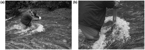
Measurement procedures for the mTVHR are different from the methods outlined by Fonstad (et al. 2005) and are designed to eliminate the issue associated with instrument rotation, while still allowing for accurate measurement of depth, and thus the ability to calculate discharge. Measurements using the mTVHR were completed as follows. The operator would position the instrument perpendicular to the tagline (i.e. parallel to streamflow) in the center of the measurement panel. A water depth was read on the downstream ruler. In conditions of pulsating flow, an averaged water depth over approximately 40 seconds was used. The mTVHR was then turned 90 degrees to be parallel to the tag line (and perpendicular to the direction of flow), and a measurement of upstream and downstream velocity-head was made using the sliding rulers. The operator slid the rulers down until each touched the meniscus of the water levels on the respective sides (Figure ). The instrument was removed from the stream and viewed at 90 degrees, directly over where the rulers overlapped. The difference between the two rulers was the velocity-head value recorded at the respective panel, which was measured in millimetres and later converted to metres. In instances of pulsing water levels, the water level was averaged on the upstream and downstream sides for approximately 40 seconds. This process was repeated for all panels in the cross section.
Figure 2. (a) Measuring velocity-head using the modified transparent velocity-head rod (mTVHR). (b) Upstream water level as viewed through the mTVHR. Ruler in the background will slide down to meet the water level (or average if fluctuating) to define the upstream velocity-head level. Images: Emilia Young.

Data analysis
Data were visually inspected to identify potentially suspect values (e.g. data entry errors) or inconsistencies (e.g. depth comparisons between measurement with the FT and with the mTVHR). All error flags (notations) produced by the SonTek FT were also reviewed for potential errors. Obvious data entry errors were corrected in the electronic data files. For the depth comparisons, visual inspection of plotted data showed most were comparable except for 17 points which occurred mostly on the edges of a few cross sections. Each suspect point was subsequently evaluated and a decision was made to omit those pairs from the analysis where FT depth = 0 m and mTVHR depth > 0 m. This situation sometimes occurred because the FT could only measure velocity in greater than 5 cm water depth, whereas the mTVHR could be used in much shallower conditions. In some instances, a depth was not taken where a velocity measurement could not be made with the FT and was miscoded as a match pair (0 m value). As the comparative standard did not exist, data could not be compared (i.e. no FT measurement). In the data set, 42 velocity data points (out of ~2400) were evaluated and corrected for velocity error flags in the FT files. Error flags produced by the FlowTracker can be warnings of violations of user-set thresholds for standard errors of velocity, velocity spikes, boundary condition violations or inadequate signal-to-noise ratios (SonTek 2009). These conditions may indicate turbulent or poor measurement conditions, often, but not always, from underwater obstacles adjacent or upstream of the measurement panel. These data were corrected using the average of the velocities in the two adjacent panels.
A linear regression analysis was used to estimate the relationship between the velocity as measured using the FT (Y) and mTVHR (2gh)0.5 (X) as outlined in Fonstad et al. (Citation2005). Residual and other diagnostic plots were inspected for violations of the standard assumptions of linear regression models. The robustness of the mTVHR instrument was assessed in several ways.
The impact of different operators on the performance of the instrument was assessed using an analysis of covariance (ANCOVA) to examine if the fitted line differed among operators. Because of the large sample size (~2400 total paired mTVHR–FT measurements), ANCOVA can detect quite small differences among the lines for individual operators. A random effects model was used to estimate the relative variation among operators compared to that of noise about the regression line.
The impact of discharge, depth and velocity on the difference in the depth measurements and on the velocity-head measurements among operators was assessed graphically using a Loess smoother. The impact of site on the difference in depth and velocity-head measurements was assessed using boxplots followed by an analysis of variance (ANOVA) and a Tukey multiple comparison procedure. Similarly, variability in estimated velocity and depth measurements among different operators was assessed using graphical methods.
The robustness of the fitted line to the depth of the measurement point was examined using ANCOVA with depth as covariate discretized into three classes (0 to 0.25 m, > 0.25 to 0.50 m, and > 0.50 m). A breakpoint model (Toms and Lesperance Citation2003) was also fitted to the data to assess at what velocity-head the relationship appears to break down at the lower velocity-head readings.
The total discharge was estimated using the mid-section method (RISC 2009) with panel width derived from the 50-m fiberglass tape, depth and velocity data from the FT, and similarly depth and velocity-head from the mTVHR using the Fonstad et al. (Citation2005) equation and our new fitted equation. If a site was measured using multiple operators on different dates, a separate estimate of discharge was determined for each operator and/or date. An omnibus measure of the difference between the discharge values was computed two ways (Equations 3 and 4):
(3)
(4)
RMSE provides the average squared absolute difference between the two values, while RMSPE is the average squared percentage difference between the two values. The RMSE measures the standard deviation of the residual above and below the regression line.
All computations were performed using R 3.1.1 (R Core Team Citation2014).
Results
The re-designed mTVHR resulted in an inexpensive and robust field instrument. No major issues were encountered with attached parts coming loose or breakage in any of the three prototypes over three years of periodic use. However, rubber O-rings did require periodic checking and replacement due to cracking. Using a thicker material in the mTVHR construction was found to reduce/eliminate bending at medium flows. The instrument still experienced deflection at the highest velocities measured, but much less than the original Fonstad et al. (Citation2005) version. This study did not specifically test for any effect of increasing the thickness of the instrument on measuring unimpeded water levels (water depths). A paired t-test was used to compare the depth as measured by the two instruments. There was no evidence of a difference in the depths reported by the two instruments (estimated mean difference [mTVHR vs. FlowTracker] is 6.4 [standard error, SE, 4.7] mm, p = 0.18). Greater variability in observed water levels during fast and/or surging water velocities were, however, sometimes observed, necessitating averaging of water depth readings taken from the upstream and downstream rulers.
Qualitatively, the addition of two rulers allowed for accurate and consistent measurement of upstream and downstream velocity-head values in the presence of refraction through the mTVHR. The comparison between operators using this dual ruler stick approach is described below.
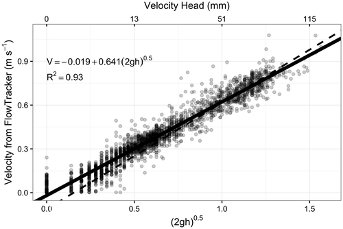
The calibration equation (Equation 5) developed for the transformed mTVHR velocity-head value [(2gh)0.5] and the velocity as measured by the FT is:
(5)
with R2 = 0.93 and RMSE = 0.06 m s−1 (Figure ). The RMSE indicates that approximately 95% of estimates will be within about 0.12 m s−1 of the FT measured velocity at most velocity levels. There are a number of points when h = 0 that clearly fall above the fitted line, but exclusion of these points did not materially change the fitted line. The residual and diagnostic plots did not show any serious violations of the assumptions for a linear regression model.
Figure 3. Data points with Fonstad et al. (Citation2005) calibration (dashed) and modified transparent velocity-head rod (mTVHR) calibration (solid), where g = 9.8 m s–2 and h is the velocity-head measured on the mTVHR (m).
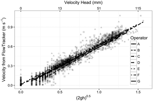
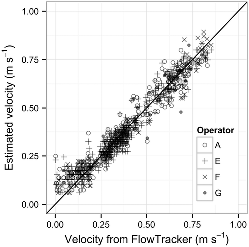
An analysis of covariance found evidence of differential fits among operators (p < 0.0001), but the large sample sizes implied that very small differences could be detected (Figure ). The fitted line that is farthest from the others appears to come from operator C who only measured one stream and had no velocity-head measurements of 0. The variance decomposition, when operators were treated as random effects, showed that the operator-to-operator standard deviation (0.016 m s−1) is approximately 25% of the residual standard deviation (0.058 m s−1), again indicating that operator effects are small.
Figure 4. Fitted lines by separate operators. There was strong evidence that the operators had different fits (p < 0.0001), but the effect of operator was small relative to residual variation. Note that Operator C only measured one stream with no measurements of a 0 mm velocity-head on the modified transparent velocity-head rod (mTVHR).
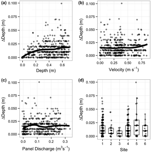
The absolute differences between the depth measurements among operators are shown in Figure . Differences in the depth measurements among operators tend to increase slightly with absolute depth, but the relative errors are small. There does not appear to be a relationship between the differences in the depth measurements among operators as a function of panel velocity or panel discharge at the point of measurement. There is evidence that the mean absolute difference among operators varies among sites (p = 0.0002), but this appears to be limited to the Goldstream River site (Figure ). The size of the differences in velocity-head measurements between operators is small relative to the actual reading.
Figure 5. Plots of the absolute difference in depth among operators measured using the modified transparent velocity-head rod (mTVHR) by (a) depth, (b) velocity, (c) calculated panel discharge and (d) site. The sites in plot (d) are 1 = Cowichan River Fish Fence; 2 = Cowichan River Smolt Fence; 3 = Cowichan River Department of Fisheries and Oceans (DFO) Side Channel; 4 = Cowichan River Trailer Park; 5 = Goldstream River; 6 = Muir Creek. The smoothed line in plots (a–c) is a loess curve. Points jittered to reduce superposition of points.
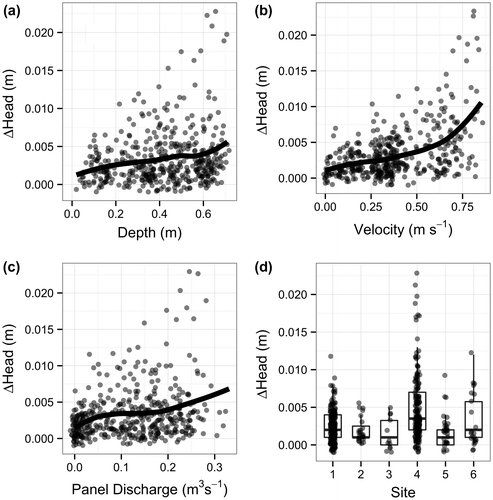
The absolute differences between the velocity-head measurements on the mTVHR among operators are shown in Figure . Differences in the velocity-head measurements among operators tend to increase with depth, velocity and calculated panel discharge. There is evidence that the mean absolute differences among operators varies among sites (p < 0.0001), but this appears to be limited to the Cowichan River Trailer Park and Muir Creek sites. The size of the absolute differences is again small.
Figure 6. Plots of the absolute difference in velocity-head reading on the modified transparent velocity-head rod (mTVHR) among operators by (a) depth, (b) velocity, (c) calculated panel discharge and (d) site. The sites in plot (d) are 1 = Cowichan River Fish Fence; 2 = Cowichan River Smolt Fence; 3 = Cowichan River Department of Fisheries and Oceans (DFO) Side Channel; 4 = Cowichan River Trailer Park; 5 = Goldstream River; 6 = Muir Creek. The smoothed line in plots (a–c) is a loess curve. Points jittered to reduce superposition of points.
The predicted velocities using the replicated measurements on the same stream by different operators and the fitted equations are shown in Figure . There does not appear to be any systematic pattern except at the very lowest readings.
Figure 7. Differences in estimated velocity among operators measuring the same stream using the fitted relationship against the velocity as measured by the FlowTracker (FT). The X = Y line is shown on the plot. Points jittered to reduce superposition of points.
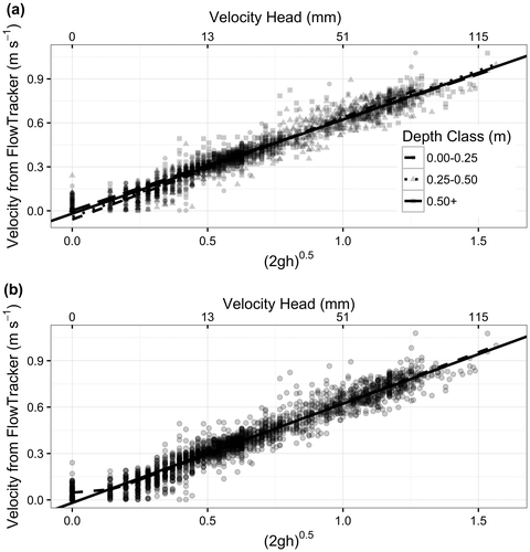
There was evidence that the relationship between the transformed mTVHR velocity-head reading and the velocity measured by the FT varies by depth (p < 0.0001), but the difference in fit is very small (Figure a). The breakpoint model (Figure b) indicates that the model should not be used for velocity-head measurement of less than 1 mm, but that the fitted model is appropriate for velocity-head measurements greater than 1 mm.
Figure 8. Estimated regression line between transformed modified transparent velocity-head rod (mTVHR) height and velocity as measured by FlowTracker (FT) (a) by depth class and (b) using a break point model. In both plots, the solid line is the fitted model using all of the data.
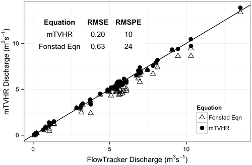
Finally, the study compared the estimated cross section discharge at each site, per field visit using the new mTVHR equation and the Fonstad et al. (Citation2005) equation with the estimated discharge from the FT (Figure ). This study compared the two different calibration equations because the TVHR and the mTVHR have the same external dimensions (9.85 cm × 100 cm) and dimensionally only differ in thickness (12 mm vs. 3.2 mm). The new mTVHR calibration equation matches the overall discharge values from the FT better (RMSE = 0.20 m s−1; RMSPE = 10%) than the Fonstad et al. (Citation2005) equation (RMSE = 0.63 m s−1; RMPSE = 24%). Notice that the RMSPE for both equations is driven mainly by small absolute errors when the total discharge is small.
Figure 9. Comparison of estimated discharges from the new modified transparent velocity-head rod (mTVHR) and the Fonstad (2005) equation compared to those estimated using the FlowTracker (FT). The solid line is X = Y. RMSE = root mean square error between the predicted discharge using the equations and the discharge as estimated using the FT; RMSPE = root mean square percentage error between the predicted discharge using the equations and the discharge as estimated using the flow meters (FT/mTVHR).
Discussion
The modifications of the mTVHR resulted in improved accuracy and precision in measurement of stream velocity as compared with the original model developed by Fonstad et al. (Citation2005). This subsequently improved upon the methods that allowed for an accurate calculation of discharge. The accuracy of both the instrument and the calibration equation have been improved through the physical modifications of the instrument and testing in a wide range of streamflow conditions. The relationship between discharge calculated by a flow meter and discharge calculated via mTVHR measurements has been improved via Equation 5.
Sources of error
The mTVHR was evaluated in laminar and semi-laminar streamflow conditions. VHR are not recommended for use in turbulent conditions (Heede Citation1974), which similarly are also not suitable for the FlowTracker or AA flow meter. The worst performance of the instrument (in comparison to the FT) was observed in conditions where the channel bed substrate varied considerably in size upstream of the cross section. This is likely because the bed materials of varying sizes were causing vertical and lateral turbulence, and therefore causing issues with the both the FT and mTVHR instruments. For example, the Goldstream River bed is composed of basketball-sized boulders and smaller baseball-sized clasts. It is very likely that the turbulent flow over and around these large bed protrusions was creating conditions of angularity of flow (not perpendicular to tag line) and that subsequently violated the requirements for a good mid-section metering location (RISC 2009).
The FT and the mTVHR also measure different portions of the water column. The FT used the 0.6 depth method (0.4 total depth from the bottom) to represent the average velocity across the full depth of panel discharge, while the mTVHR integrates the entire water column. Fonstad et al. (Citation2005) hypothesized that flow near the upper water surface exerts a greater influence on the mTVHR-measured velocity and was a source of the consistent overestimates of velocity that they measured. In situations where upstream turbulence around boulders is causing greater variation of velocities in the water column, all methods may be in error due to non-standard velocity profiles such that using the assumptions of 0.6 depth or 0.8/0.2 depth will not be representative of average velocity conditions (Heede Citation1974). It is not recommended to use either instrument in situations of extreme variability in bed material size and, in particular, in situations where upstream bed textures are creating highly non-laminar flow.
Another potential source of error was conditions of surging water velocities observed as rapidly fluctuating water levels on the mTVHR. Most streams had some degree of velocity variation. The FT identifies situations in error to be those where the standard error of the velocity measurement is typically greater than 0.01 m s−1 (SonTek 2009). In situations of rapidly surging water levels, operators of the mTVHR needed to visually estimate a midpoint between the high and low boundaries of the fluctuating water level. This estimation would occur over a period of approximately 40 seconds to be consistent with the FT sampling interval. It is assumed that not all operators would be equally skilled in this task, and therefore greater uncertainty under these conditions would be expected.
A final potential source of error in the use of the mTVHR is the issue of refraction with respect to velocity-head measurement. Modifications of using sliding rulers to physically touch the upstream and downstream meniscus (water heights) reduced the potential for errors in determining velocity-head due to varying observer viewing angles. No matter what angle is viewed through the instrument, physically touching the water surface made identifying the velocity-head consistent among observers. A related source of measurement error is that any final velocity-head reading could vary by a few millimetres if the observer did not view the difference between the rulers perpendicular to the operator’s line of sight. Viewing final measured velocity-head through the mTVHR needed to be square to the rod; otherwise, the velocity-head recorded would either increase or decrease depending on the direction of tilt of the instrument. All observers were made aware of this issue, but it is still a likely source of some variability between operators.
Comparison of users
This paper is the first attempt to formally compare velocity-head rod measurements between multiple users. The comparisons indicated that there was evidence of a difference between users in velocity-head measurements (operator standard deviation [0.016 m s−1] is approximately 25% of the residual standard deviation [0.058 m s−1]), but that differences in operational use of the instrument between operators were very small (Figure ). As such, the mTVHR is well suited for use by a diverse audience, from professionals to students, with the expectation of accurate and precise data collection.
Discharge estimates
Discharge estimates made with the mTVHR and new calibration equation were comparable to those made using the FT. The new calibration equation improved the discharge estimates relative to the Fonstad et al. (Citation2005) equation which consistently underestimated discharge relative to the FT. The error with the mTVHR and new calibration equation reduced the RMSE by two thirds, increasing confidence in this method. The mTVHR and new calibration equation with multiple users are typically within 10% of the FT measured discharge across sites, as compared with the Fonstad et al. (Citation2005) equation which in this experiment was typically found to be within 24% (Figure ).
Limitations of use
Use of the mTVHR should be limited to wadeable streams where the maximum depth is less than 0.75 m. This depth limit is recommended to ensure there is sufficient length at the top of the rod for at least 0.25 m of water level (velocity-head) rise. At higher velocities, the mTVHR may need to be restricted to even lower water depths. It could, however, be used at deeper depths (> 0.75 m) provided there is enough room left on the instrument to measure the fastest velocity across the stream cross section. In these situations, the metre sticks extend far above the end of the mTVHR, making the instrument unwieldy to use in deep water. In this circumstance, it is possible to substitute shorter desktop rulers (30 cm) for the metre sticks. The mTVHR was not comparatively tested at water depths less than 5 cm, because this was the lower limit that could be measured with an FT. As such, results derived using the mTVHR and calibration equation below 5 cm depth should be used with caution.
The mTVHR is effective for measuring velocity-heads ranging from 2 to 100 mm. Experience with measurements of velocity-head greater than 100 mm indicate that bending of the mTVHR and water level fluctuations make it difficult to handle and potentially dangerous to stand behind (should it dislodge and recoil towards the observer; Figure ). Shin and leg injuries could potentially result. Use of the mTVHR is also not recommended below 2 mm in velocity-head even though the breakpoint model indicates a 1 mm threshold. This is because of the potential source of error in reading the overall velocity-head due to refraction issues. Some of the least accurate estimated discharges were in cross sections that were dominated by low velocity-head values of < 7 mm. In practice, it may be prudent to relocate a measurement cross section to an area with faster stream velocities to make measurements. In addition, areas of rapidly surging water levels should likely be avoided as this will slow the use of the mTVHR. In many instances, averaging of velocity-head measurements over a span of 40 seconds will be required under conditions of surging water levels (velocities) to obtain an accurate estimate of velocity.
Conclusions
The mTVHR extends the work of Fonstad et al. (Citation2005) in the design, construction and testing of an inexpensive but accurate method to measure streamflow velocities. The instrument is easy to construct and robust in the field. The results of testing and calibration show that the mTVHR can be used by anyone requiring a measurement of depth or velocity in laminar to semi-laminar, wadeable conditions less than 0.75 m in depth and less than 1 m s−1 velocity. The instrument is easy to use, constructed with commonly available materials, has no mechanical parts that will wear and requires no batteries. Velocity-head data collected with the mTVHR can be easily converted to velocity values using the calibration equation provided (users must maintain the dimensions of the mTVHR specified in this manuscript).
The results of the mTVHR testing show the instrument compares well to the FT. Operator comparability in measuring depths and velocities was shown to be consistent enough to provide reliable estimates of discharge when using the mid-section method (RISC 2009).
There is a great potential for widespread use of the mTVHR. Due to its low cost and simple construction, the instrument is well suited to use by academic institutions and field personnel. Given the ease of use and high quality of data, the mTVHR method is recommended to be used in place of the less rigorous velocity-head rod approaches used in current ecological assessment protocols (Harding et al. Citation2009; Environment Canada Citation2012Citation). Because of its small size and the fact that it requires no streamside calibration, the instrument can be carried with relative ease in the field and can be stored in a vehicle or storage shed near a hydrometric station. It is stressed that the key to the proper use of the mTVHR is the recognition and avoidance of streamflow conditions that violate the mid-section method and site selection criteria for wadeable streams.
Acknowledgements
The authors thank the following for their input and assistance with this project: Emilia Young, Geneen Russo, Peter Tschaplinski, Celine Davis, Gabe Sentlinger, Kevin Rieberger, Jennifer Turner, Sylvia Barroso, Joanne McLeod and Warren Cooper. The authors also thank the editors and two anonymous reviewers for their comments which helped to improve the manuscript.
References
- Carufel, L. H. 1980. Construction and use of a velocity-head rod for measuring stream velocity and flow. Anchorage: Bureau of Land Management, BLM/AK Technical Report 5, 11 pp.
- Ciborowski, J. J. H. 1991. Head tube: A simple device for estimating velocity in running water. Hydrobiologia 222: 109–114.
- Drost, H. 1963. Velocity-head rod for measuring stream flow. Journal of Hydrology, New Zealand 2 : 7–11.
- Environment Canada. 2012. Canadian aquatic biomonitoring network: Field manual – wadeable streams. Ottawa: Environment Canada, 57 pp.
- Fonstad, M. A., J. P. Reichling, and J. W. Van de Grift. 2005. The transparent velocity-head rod for inexpensive and accurate measurement of stream velocities. Journal of Geoscience Education 53 (1): 44–52.
- Gordon, N. D., T. A. McMahon, B. L. Finlayson, C. J. Gippel, and R. J. Nathan. 2004. Stream hydrology: An introduction for ecologists. Chichester, UK: John Wiley & Sons Inc., 429 pp.
- Harding, J., J. Clapcott, J. Quinn, J. Hayes, M. Joy, R. Storey, H. Greig, J. Hay, T. James, M. Beech, R. Ozane, A. Meredith, and I. Boothroyd. 2009. Stream habitat assessment protocols for wadeable rivers and streams of New Zealand, 136. Christchurch: University of Canterbury.
- Heede, B. H. 1974. Velocity-head rod and current meter use in boulder-strewn mountain streams. USDA Forest Service Research Note RM-271. 4 pp. Fort Collins, Colorado.
- R Core Team. 2015. R: A language and environment for statistical computing. Vienna, Austria: R Foundation for Statistical Computing. http://www.R-project.org/ Access date April 27, 2015.
- Resources Information Standards Committee (RISC). 2009. Manual of British Columbia hydrometric standards. Version 1.0, 12 March 2009. Resources Information Standards Committee. Victoria: British Columbia Ministry of Environment, 222 pp.
- SonTek. 2009. FlowTracker handheld ADV user's manual, firmware version 3.7. SonTek. Accessed April 27, 2015.
- Toms, J. D., and M. L. Lesperance. 2003. Piecewise regression: A tool for identifying ecological thresholds. Ecology 84: 2034–2041.
- Wilm, H. G., and H. C. Storey. 1944. Velocity-head rod calibrated for measuring streamflow. Civil Engineer 14(11): 475–476.

