Abstract
Induction motor is the most frequently used electric machine in industrial and commercial applications because of its well-known advantages, including robustness, low price, maintenance free, and line start. The exact knowledge of some of the induction motor parameters is very important to implement efficient control schemes and its in situ efficiency determination. These parameters can be obtained by no-load test that is not easily possible for the motors working in process industries where continuous operation is required. In this present study, particle swarm optimization, differential evolution, and some of their recent variants are used for in situ efficiency determination of induction motor (5 hp) without performing no-load test. Detailed information about the methods for efficiency measurement is given. Results are compared with genetic algorithm and a physical efficiency measurement method, called torque-gauge method. The performances in terms of objective function (error in the efficiency) and convergence time prove the effectiveness of optimization algorithms used in this article.
INTRODUCTION
Induction motors have become the most widely used machines in any industry, consuming around 70% of the electricity used. Process industries are found to be energy intensive (4% of energy cost in the total input cost in case of textile industry) compared with other industries, such as chemical, food, and computer manufacturing (Palanichamy et al. Citation2001). Therefore, a small increment in the efficiency of these motors can result in substantial savings over a long period. In addition, motors operating at light or partial load (no balance in between copper and iron losses) result in considerable reduction in the efficiency and power factor. Adjustment of motor excitation with respect to motor load and speed helps energy conservation in these motors. But adoption of energy conservation by adjusting motor excitation or replacing it by energy-efficient motors depends highly on the savings and payback periods. In this situation an accurate in situ efficiency determination of these motors is essential but requires the motor's electrical parameters.
Many nonlinear programming techniques like the Newton-Raphson technique, cyclic method, Hook, Jeeves, and Rosenbrock methods have been applied to parameter estimation and hence efficiency determination of induction motors. The optimum determined by the Newton-Raphson technique depends heavily on the initial guess of the parameter, with the possibility of a slightly different initial value, causing the algorithm to converge to an entirely different solution (Nangsue et al. Citation1999). Also, this algorithm needs derivative during the optimization process, which may be difficult to calculate. Bounekhla, Zaim, and Rezzoug (Citation2005) proved the Rosenbrock method is better than scatter search and Hook and Jeeves methods in terms of fast and efficient search. Apart from conventional methods, some of the evolutionary techniques like genetic algorithm (GA) (Pillay et al. Citation1998), genetic programming (Nangsue, Pillay, and Conry Citation1999), particle swarm optimization (PSO) (Benaidja and Khenfer Citation2006), differential evolution (DE) (Ursem and Vadstrup Citation2003), evolution strategy (Ursem and Vadstrup Citation2004), and a PSO variant (Ursem and Vadstrup Citation2004) have been successfully applied to induction motor parameter (electrical and mechanical) estimation.
In continuation with the above studies, in the present study we propose the use of several variants of PSO, quantum PSO (QPSO), and DE and their variants (ATREPSO, GMPSO, SMPSO, LXDE, and DE-QI) to the in situ efficiency determination of induction motor. A wide comparison is performed on the results obtained from these algorithms along with GA (Pillay et al. Citation1998) and the torque-gauge method (Ontario Hydro Report Citation1990).
The article is organized as follows. Section 2 explains the standards for induction motor efficiency determination. Section 3 describes the optimization algorithms used in this study. In section 4 mathematical model of the in situ efficiency determination is given, and section 5 gives the experimental settings of all algorithms. In section 6 results and discussions are given, and section 7 is the conclusion.
STANDARDS FOR INDUCTION MOTOR EFFICIENCY DETERMINATION
The methods for efficiency measurements can roughly be divided into two categories: direct and indirect methods. In the direct method shaft torque is measured directly and efficiency is calculated by using the ratio of motor's output power to input power. The preferred method of determining efficiency in three-phase induction motor, however, is the summation-of-losses method.
The international standards IEEE 112 (United States; IEEE standard Citation2004), IEC 34-2 (European; IEC standard Citation1972), and IS 325: subrule IS 4029 (Indian standard Citation2002) represent the most important references for the three-phase induction motor efficiency measurements. These standards recommend different measurement procedures, in particular for the stray losses determination and the temperature corrections of the copper losses.
IEEE 112-2004 (previously known as IEEE 112-1996) (IEEE standard Citation2004) consists of five basic methods to determine the efficiency: A, B, C, E, and F. In method A the input and output powers are measured and the efficiency is directly obtained. This method is only used for very small machines. Method B uses a direct method to obtain the stray load losses but not a direct method for determining the motor efficiency. To reduce the influence of the measuring error, a linear regression is made of the stray load losses at different loads versus the torque squared.
Method B is the recommended method for testing of induction machines up to 180 kW. Method C is a back-to-back machine test. The total stray load losses are also obtained via a separation of losses for both motor and generator. The stray load losses are then divided between the motor and generator proportional to the rotor currents.
E and E1 are indirect methods where the output power is not measured. In method E the stray load losses are directly measured using the reverse rotation test. In method E1 the stray load losses are set to an assumed value. It has been shown experimentally that IS 325 is similar to IEEE 112-E (Thangaraj, Agarwal, and Srivastava Citation2007).
In methods F and F1 the equivalent circuit of the machine is used and is more advantageous when tests under load are not feasible or not desirable (Pillay et al. Citation1998). The stray load losses are again directly measured, or in the case of F1 an assumed value is used. The method developed in Otaduy (Citation1996) requires only speed measurement and nameplate data to construct an equivalent circuit with electrical parameters.
OPTIMIZATION ALGORITHMS USED FOR THIS STUDY
Standard Particle Swarm Optimization
PSO was proposed by Kennedy and Eberhart (Citation1995). The mechanism of PSO is inspired from the complex social behavior shown by the natural species. For a D-dimensional search space the position of the ith particle is represented as X i = (x i1, x i2, … , x iD ). Each particle maintains a memory of its previous best position P besti = (p i1, p i2, … ,p iD ). The best one among all the particles in the population is represented as P gbest = (p g1, p g2, … , p gD ). The velocity of each particle is represented as V i = (v i1, v i2, … ,v iD ). In each iteration the P vector of the particle with best fitness in the local neighborhood, designated g, and the P vector of the current particle are combined to adjust the velocity along each dimension and a new position of the particle is determined using that velocity. The two basic equations that govern the working of standard PSO (SPSO) are that of velocity vector and position vector given by
SMPSO Algorithm
The SMPSO algorithm (Pant et al. Citation2008) is an extension to the SPSO algorithm by including the component of mutation in it. The mutation operator defined in the SMPSO algorithm uses quasi-random Sobol sequence and is called a systematic mutation (SM) operator. In the SMPSO algorithm the worst particle of the swarm is mutated by the use of SM operator.
The SM operator is defined as
The idea behind applying the mutation to the worst particle is to push the swarm from the back. The quasi-random numbers used in the SM operator allows the worst particle to move forward systemically.
GMPSO Algorithm
In GMPSO, Gaussian mutation operator is developed for updating the position of the swarm particles (Pant, Thangaraj, and Singh Citation2008). The mutation operator is activated only when the diversity of the swarm becomes less than a certain threshold (say d low).
The algorithm uses the general Eqs. (Equation1) and (Equation2) for updating the velocity and position vectors. At the same time a track of diversity is also kept that starts decreasing slowly and gradually after a few iterations because of the fast information flow between the swam particles, leading to clustering of particles. It is at this stage that the Gaussian mutation operator given as X t+1[i] = X t [i] + η ∗ Rand, where Rand is a random number generated by Gaussian distribution, is activated with the hope to increase the diversity of the swarm population. Here η is a scaling parameter.
ATREPSO Algorithm
The ATREPSO (Pant et al. Citation2007) is a simple extension of the attractive and repulsive PSO (ARPSO) proposed by Riget and Vesterstrom (Citation2002), where a third phase called in-between phase or the phase of positive conflict is added. In ATREPSO the swarm particles switch alternately between the three phases of attraction, repulsion, and an in-between phase, which consists of a combination of attraction and repulsion. The three phases are defined as follows:
-
Attraction phase (when the particles are attracted towards the global optimal)
-
Repulsion phase (particles are repelled from the optimal position)
-
In-between phase (neither total attraction nor total repulsion)
In the in-between phase the individual particle is attracted by its own previous best position p id and is repelled by the best known particle position p gd . In this way there is neither total attraction nor total repulsion but a balance between the two.
The swarm particles are guided by the following rule:
Quantum Particle Swarm Optimization
QPSO is also a variant of SPSO. In the quantum model of a PSO, the state of a particle is depicted by wave function,Ψ(x, t), instead of position and velocity. The dynamic behavior of the particle is widely divergent from that of the particle in traditional PSO systems. In this context the probability of the particle's appearing in position x i from probability density function|Ψ(x, t)|2, the form of which depends on the potential field the particle, lies in Liu, Sun, and Xu (Citation2006).
The particles move according to the following iterative equations (Sun, Feng, and Xu Citation2004; Sun, Xu, and Feng Citation2004):
Differential Evolution
DE is an evolutionary algorithm proposed by Storn and Price (Citation1995). DE is similar to other evolutionary algorithms, particularly GAs (Goldberg Citation1986), in the sense that it uses the same evolutionary operators like selection recombination and mutation like that of GA. However, the significant difference is that DE uses distance and direction information from the current population to guide the search process. The performance of DE depends on the manipulation of target vector and difference vector to obtain a trial vector. Mutation is the main operator in DE. A brief working may be described as follows: For a D-dimensional search space, each target vector x i,g , a mutant vector is generated by
The selection step chooses the vector between the target vector and the trial vector with the aim of creating an individual for the next generation.
LXDE Algorithm
The LXDE algorithm (Pant, Thangaraj, and Abraham Citation2009) is a modified version of classical DE algorithm. In the LXDE algorithm a new mutant vector is proposed by the use of Laplace distribution. The mutation operation in LXDE makes use of only two candidate vectors, in place of three candidate vectors like the usual mutation operation given in Eq. (Equation10), to produce a mutant vector. Further, instead of using the fixed value of F as in basic, we use a random number based on Laplace distributed random numbers as scaling or amplitude factor.
DE-QI Algorithm
The DE-QI algorithm (Pant, Thangaraj, and Singh Citation2009) is also a modified version of classical DE algorithm. In the DE-QI algorithm a mutation probability P qi having a certain threshold value is fixed by the user. In every iteration, if the uniformly distributed random number U(0, 1) is less than P qi , then the mutant vector is generated by using QI operator; otherwise, the mutant vector follows the classical DE method. The QI operator, based on quadratic interpolation (Mohan and Shankar Citation1994), is a nonlinear operator that produces a new candidate solution lying at the point of minima of the quadratic curve passing through the three selected candidates.
It uses a = X
min, and two other randomly selected particles {b, c} (a, b, and c are different particles) from the population to determine the coordinates of the new particle where
The nonlinear nature of the QI operator used in this work helps in finding a better solution in the search space. The interpolation approach increases the exploratory capabilities of the DE as it keeps on looking for points lying in between the three selected candidates. The selection of the best candidate (a = X min) makes it behave like a greedy because it is always looking for a new candidate in the vicinity of the best solution obtained so far.
Genetic Algorithms
GAs are perhaps the most commonly used evolutionary algorithm for solving optimization problems. The natural phenomenon that forms the basis of GA is the concept of survival of the fittest. GAs were first suggested by John Holland and his colleagues (Citation1975). The main operators of GA are selection, reproduction, and mutation. They work with a population of solutions called chromosomes. The fitness of each chromosome is determined by evaluating it against an objective function. The chromosomes then exchange information through their operators; crossover or mutation. More detail on the working of GAs may be obtained from Goldberg (Citation1986).
IN SITU EFFICIENCY DETERMINATION
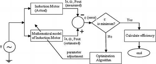
The method described here considers IEEE E1 and F1 methods of efficiency determination but no-load measurements are not performed. We followed the same procedure as that of Pillay et al. (Citation1998) but instead of using GA we used PSO, DE, and their variants to solve algebraic equations. The general block diagram of in situ efficiency determination of induction motor using optimization algorithms is shown in Figure .
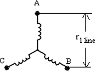
First, the stator line resistance is measured after shutting down the motor. 5hp, four-pole induction motor considered as test motor. “Summation of losses” method for efficiency determination is used with the assumption of stray load losses. The winding arrangement of a star connected motor is shown in Figure and the resistance per phase is calculated as in Eq. (Equation13).
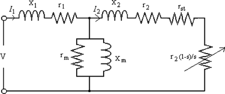
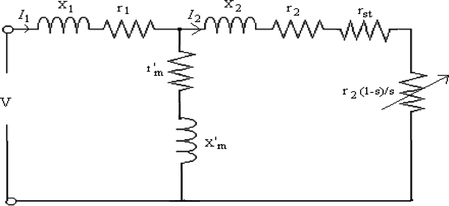
Some measurements on the motor are required before to run the optimization algorithm to estimate the motor parameters: stator line to line voltage V 1, stator current I 1, input power P inp, and rpm at difference load points. Then, power factor can be calculated as in Eq. (Equation14). The measured and calculated values of the test motor for a wide range of loads and the equivalent circuits considered here are taken from Pillay et al. (Citation1998) and are shown in Table and Figures and , respectively.
TABLE 1 Measured Data of the Test Motor
Two variations were performed in these circuits from the conventional exact equivalent circuit for comparison: (1) inclusion of stray load loss resistance r
st
, shown in Figure and (2) parallel connection of X
m
, r
m
is transformed into series connection as , shown in Figure , and its calculation can be performed as in Eq. (Equation15).
The next step is to find the stray load losses at any load point from its assumed value at full load as per the recommendation in IEEE standards section 5.7.4 (IEEE standard Citation2004). The recommended value of stray load losses for different capacity motors is shown in Table . In the present study we considered this loss at full load is 1.8% and its calculation at different load point is shown in Eq. (Equation16). The remaining Eqs. (17) through (32) of induction motor that are involved in the present study are as follows (Pillay et al. Citation1998):
TABLE 2 Stray Load Losses for the Different Capacity Motors
The stray load loss resistance r st is
Temperatures of stator and rotor windings are assumed to be the same and calculated as in Eq. (Equation18) with the IEEE recommended reference temperature.
Equations (Equation19) and (Equation20) are used to correct the stator and rotor resistances to the test temperature:
The complex admittances of the branches of the equivalent circuits of Figures and are given below (Pillay et al. Citation1998).
The power factor and rotor current can be estimated as
In method 1, the objective function is
In method 2, the objective function includes stator current, input power, and power factor, which is
In method 3, the objective function includes stator current, input power, and output power, which is
In method 4, the objective function includes four input parameters: stator current, input power, power factor, and output power. The objective function is
The decision variables of the above objective functions are x 1, r 2, x m (or x m ′) and r m (or r m ′). The optimization algorithms are used to determine the above said unknown variables. The assigned parameters of the given motors are K a = 225, K c = 234.5, r 1 = 1.635 ohm.
EXPERIMENTAL SETTINGS
For all the PSO algorithms the inertial weight w is taken to be linearly decreasing from 0.9 to 0.5 and the acceleration constants c 1 and c 2 are taken as 2.0 each. For QPSO algorithm, the parameter β is linearly decreasing from 1.0 to 0.5.
DE parameters crossover rate C r and scaling factor F are taken as 0.2 and 0.5, respectively, for all DE algorithms. Besides these settings a total of 30 runs for each experimental setting were conducted and the average efficiency was recorded. Results for GA are noted from the literature (Pillay et al. Citation1998).
RESULTS AND DISCUSSION
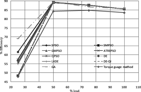
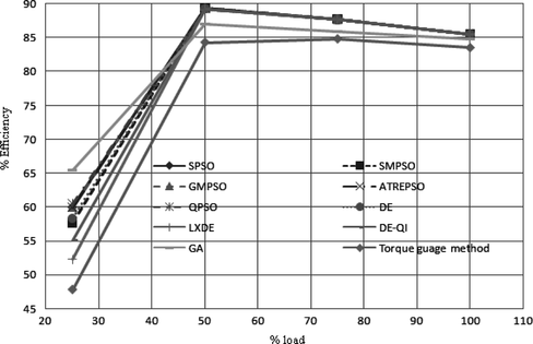
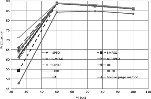
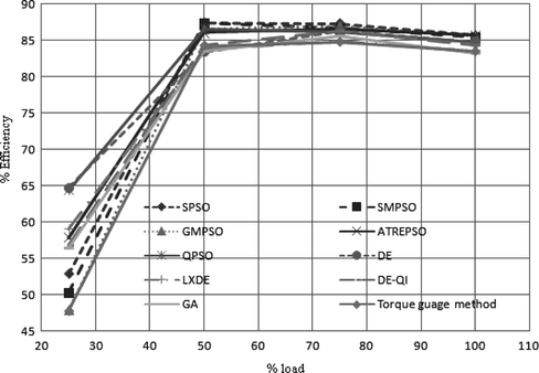
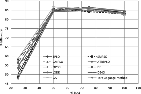
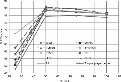
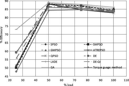
The comparison results of all algorithms corresponding to Figure are given in Tables through . Tables through show the comparison results of given algorithms corresponding to Figure . Performance curves of algorithms are described in Figures through . Figures through illustrate the comparison among the optimization algorithms at 25% load for Figure .
FIGURE 12 Comparison of algorithms for objective function ff 1 at 25% load corresponding to Figure 4.
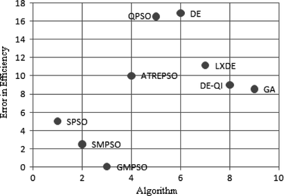
FIGURE 13 Comparison of algorithms for objective function ff 2 at 25% load corresponding to Figure 4.
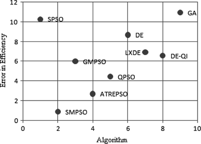
FIGURE 14 Comparison of algorithms for objective function ff 3 at 25% load corresponding to Figure 4.
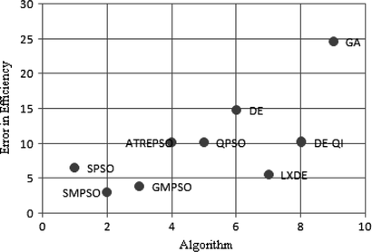
FIGURE 15 Comparison of algorithms for objective function ff 4 at 25% load corresponding to Figure 4.
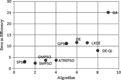
TABLE 3 Comparison Results of Algorithms in Terms of Efficiency and Error: Objective Function ff 1 of Figure
TABLE 4 Comparison Results of Algorithms in Terms of Efficiency and Error: Objective Function ff 2 of Figure
TABLE 5 Comparison Results of Algorithms in Terms of Efficiency and Error: Objective Function ff 3 of Figure
TABLE 6 Comparison Results of Algorithms in Terms of Efficiency and Error: Objective Function ff 4 of Figure
TABLE 7 Comparison Results of Algorithms in Terms of NFE and Time (sec): Objective Function ff 1 of Figure
TABLE 8 Comparison Results of Algorithms in Terms of NFE and Time (sec): Objective Function ff 2 of Figure
TABLE 9 Comparison Results of Algorithms in Terms of NFE and Time (sec): Objective Function ff 3 of Figure
TABLE 10 Comparison Results of Algorithms in Terms of NFE and Time (sec): Objective Function ff 4 of Figure
TABLE 11 Comparison Results of Algorithms in Terms of Efficiency and Error: Objective Function ff 1 of Figure
TABLE 12 Comparison Results of Algorithms in Terms of Efficiency and Error: Objective Function ff 2 of Figure
TABLE 13 Comparison Results of Algorithms in Terms of Efficiency and Error: Objective Function ff 3 of Figure
TABLE 14 Comparison Results of Algorithms in Terms of Efficiency and Error: Objective Function ff 4 of Figure
Comparison among the four methods in terms of error in the efficiency estimation indicate that the methods corresponding to Figure , which are considered the equivalent circuit with a series connection of , gave better results than one with parallel connection of
. The addition nameplate output power (method 3) to the inputs of the algorithm helps to achieve minimum convergence time and number of function evaluations (NFE) at all the loads. However, no positive effect of this variable is in the error minimization. The standard deviation of method 3 in each run is 6.08e−7, which proves its superiority, whereas the standard deviation value in method 1 is 4.65e−5. Method 4, which considered all four inputs to the algorithm, produced poor results compared with method 3 in terms of convergence time and NFE.
The results from methods 3 and 4 indicate that the effect of third (power factor) input parameter in the performance of the algorithms is almost negligible. But its contribution in method 2 is significant because it gave good performance compared with method 1. Hence, the parameters, namely current, input power, speed, and output power, are sufficient to determine the motor parameters quickly. If the knowledge of output power is not available, power factor should be considered in addition with the first two inputs to get better performance.
In comparison with the optimization algorithms in terms of error, the results indicate that LXDE outperformed the other algorithms at 100% load. ATRE-PSO and DE-QI algorithms produced better results at 75% and 50% loads, respectively. At 25% load, variants of PSO (SMPSO and ATRE-PSO) outperformed the other algorithms.
In comparison with the algorithms in term of convergence speed, the results showed that DE-QI offered better performance than all other algorithms at 100% and 75% loads; SMPSO at 50% load and almost all algorithms at 25% load performed well.
Overall, we can say that method 2, which is solved by the variants of optimization algorithms based on diversity and mutation, gave better results in most cases in terms of accuracy in efficiency estimation. Method 3 solved by the variants of algorithms based on mutation offered very good results in terms of convergence time at all the load points.
CONCLUSION
In this article we compared PSO, DE, and their variants (six improved versions) with GA and torque-gauge methods for in situ efficiency determination of an induction motor through parameter identification. This problem was framed by four different methods. The differences in methods were based on the number of input parameters used in the optimization algorithms and modifications in the equivalent circuit of the motor. All algorithms proved their numerical stability and their robustness toward error minimization in a short time.
In summary, diversity- and mutation-based variants of PSO and DE outperformed the other algorithms in most cases in terms of efficiency evaluation. In the case of convergence speed, mutation-based variants of PSO and DE were winners in all cases. The influence of output power as an input parameter of the algorithm is significant. Finally, induction motor in situ efficiency can be accurately calculated by using input power, current, speed, and output power as the input parameters of optimization algorithms. Modification in the equivalent circuit of the induction motor helped to estimate the efficiency with high accuracy.
REFERENCES
- Benaidja , N. , and N. Khenfer . 2006 . Identification of asynchronous machine parameters by evolutionary techniques . Electric Power Components and Systems 34 : 1359 – 1376 .
- Bounekhla , M. , M. E. Zaim , and A. Rezzoug . 2005 . Comparative study of three minimization methods applied to the induction machine parameters identification using transient stator current . Electric Power Components and Systems 33 : 913 – 930 .
- Goldberg , D. 1986 . Genetic algorithms in search optimization and machine learning . Reading , MA : Addison Wesley .
- Holland , J. H. 1975 . Adaptation in natural and artificial systems: An introductory analysis with applications to biology, control, and artificial intelligence . Ann Arbor , MI : University of Michigan Press .
- IEC Standard . 1972 . Rotating electrical machines—Part 2: Methods for determining losses and efficiency of electrical machinery from tests (excluding machines for traction vehicles) with amendments 1: 1995 and 2: 1996, IEC Std 60 034-2 .
- IEEE Standard . 2004 . IEEE Power Engineering Society, IEEE standard test procedure for poly phase induction motors and generators, IEEE Std: 112-2004, November 4, 2004 .
- Indian Standard . 2002 . Indian standard, Guide for testing three phase induction motor. IS Std: 4029 .
- Kennedy , J. , and R. Eberhart . 1995 . Particle swarm optimization . IEEE International Conference on Neural Networks (Perth, Australia), IEEE Service Center , 1942 – 1948 . Piscataway , NJ .
- Liu , J. , J. Sun , and W. Xu . 2006 . Quantum-behaved particle swarm optimization with adaptive mutation operator. ICNC 2006, Part I , 959 – 967 . Berlin Heidelberg : Springer-Verlag .
- Mohan , C. , and K. Shanker . 1994 . A controlled random search technique for global optimization using quadratic approximation . Asia-Pacific Journal of Operational Research 11 : 93 – 101 .
- Nangsue , P. , P. Pillay , and S. E. Conry . 1999 . Evolutionary algorithms for induction motor parameter determination . IEEE Transaction on Energy Conversion 14 ( 3 ): 447 – 453 .
- Ontario Hydro Report . 1990 . In-plant electric motor loading and efficiency techniques. Ontario Hydro Report TSDD-90-043. Toronto, ON, Canada .
- Otaduy , P. 1996 . Oak Ridge motor efficiency and load—A computer program for in-service estimation of motor efficiency and load with minimum intrusion: users guide, ORNL/MC-ORMEL1 . Oak Ridge , TN , USA : Oak Ridge National Laboratory .
- Palanichamy , C. , C. Nadarajan , P. Naveen , N. S. Babu , and Dhanalakshmi . 2001 . Budget constrained energy conservation—An experience with a textile industry . IEEE Transaction on Energy Conversion 16 ( 4 ): 340 – 345 .
- Pant , M. , R. Thangaraj , and A. Abraham . 2009 . Differential evolution with laplace mutation operator. IEEE Cong. on Evolutionary Computation, IEEE, USA, 2841–2849.
- Pant , M. , R. Thangaraj , and V. P. Singh . 2007. A simple diversity guided particle swarm optimization. IEEE Cong. on Evolutionary Computation , 3294–3299. IEEE Press: USA.
- Pant , M. , R. Thangaraj , and V. P. Singh . 2008 . A new diversity based particle swarm optimization using Gaussian mutation . International Journal of Mathematical Modeling, Simulation and Applications 1 ( 1 ): 47 – 60 .
- Pant , M. , R. Thangaraj , and V. P. Singh . 2009 . A new differential evolution algorithm for solving global optimization problems . Int. Conf. on Advanced Computer Control , 388 – 392 . Washington , DC , USA : IEEE Computer Society Press .
- Pant , M. , R. Thangaraj , V. P. Singh , and A. Abraham . 2008 . Particle swarm optimization using Sobol mutation . Int. Conf. on Emerging Trends in Engineering and Technology , 367 – 372 . Washington , DC , USA : IEEE Computer Society Press .
- Pillay , P. , V. Levin , P. Otaduy , and J. Kueck . 1998 . In situ induction motor efficiency determination using genetic algorithm . IEEE Transaction on Energy Conversion 13 ( 4 ): 326 – 333 .
- Riget , J. , and J. S. Vesterstrom . 2002 . A diversity-guided particle swarm optimizer—the arPSO. Technical report, EVAlife, Dept. of Computer Science, University of Aarhus, Denmark.
- Storn , R. , and K. Price . 1995 . Differential evolution—A simple and efficient heuristic for global optimization over continuous spaces . Journal Global Optimization 11 : 341 – 359 .
- Sun , J. , B. Feng , and W. Xu . 2004 . Particle swarm optimization with particles having quantum behavior . In Proc. of Congress on Evolutionary Computation , 325 – 331 . New Jersey , USA : IEEE Press .
- Sun , J. , W. Xu , and B. Feng . 2004 . A global search strategy of quantum-behaved particle swarm optimization . In Proc. of the 2004 IEEE Conf. on Cybernetics and Intelligent Systems , 291 – 294 . New Jersey , USA : IEEE Press .
- Thangaraj , C. , P. Agarwal , and S. P. Srivastava . 2007 . Indian standard IS 325: A review . Engineering Advances Magazine 19 ( 4 ): 24 – 32 .
- Ursem , R. K. , and P. Vadstrup . 2003 . Parameter identification of induction motors using differential evolution . In Proc. IEEE congress on Evolutionary Computation , 790 – 796 . New Jersey , USA : IEEE Press .
- Ursem , R. K. , and P. Vadstrup . 2004 . Parameter identification of induction motors using stochastic optimization algorithms . Applied Soft Computing 4 ( 1 ): 49 – 64 .
