Abstract
Knowledge representation is an essential element of a problem-solving technique through computational work. This article describes the knowledge representation scheme formulated to represent a problem in the structural analysis domain for solution through case-based reasoning (CBR). The numerical knowledge is extracted from a real-life problem that can be used as an input in a case-based reasoner. The geometric topology, loading, and mesh distribution for structure from a solved problem is represented in the form of numerical values for easy adaptation by the new problem. The representation scheme is a step forward in development of a system to be utilized for the time-consuming structural analysis requiring heavy computational power, such as an aircraft wing and fuselage components. The success of the representation strategy is a proof that CBR can work as a powerful problem-solving tool in this domain.
HISTORICAL BACKGROUND
Over the years, researchers in the artificial intelligence (AI) domain have highlighted several limitations of traditional expert systems (Cowan Citation2001). Another comparative study identifies the relative strengths and weaknesses of different approaches (Venkatasubramanian et al. Citation2003). Because of various limitations such as exhibition of fragile or abrupt behavior and restricted learning from experiences, large production systems are unmanageable and their use is discouraged in the engineering domain in general and in the structural domain in particular (Khan, Ming, and Zhang Citation1997).
Many engineering problems are solved by the use of specific expert systems developed by engineers, and these systems are truly becoming standard tools of the researchers and engineering professionals. The model generation methods and software packages, which were developed in three decades prior to 1988, had only partially relieved the structural analysis burden, because attributes of structure such as force, boundary, and materials were not considered (Lee and Lo Citation1994). In the 1980s, the concept of expert systems was recognized in the engineering domain and publications addressing intelligence-based assistance started to appear. SACON (Sriram, Maher, and Fenves Citation1985) was developed to assist the user in the selection of an appropriate analysis strategy; it was an attempt to deal with the structural modeling problem. FEASA (Taig Citation1986) was another effort that assisted the users of finite elements in specification and modeling. PLASTRAN, FACS, and CARTER (Reynier Citation1986; Cagan and Genberg Citation1987; Gregory and Shephard Citation1987) are some other examples in same category. Later, in the early 1990s, EXPERT ASSISTANT (Labrie et al. Citation1994) and FEMES (Yaonan and Yuanming Citation1995) were developed as additional fruitful efforts in the domain. It was realized that solution to the level of human experts, in this domain, would result in large, unmanageable production systems (Díaz-Agudo and González-Calero Citation2000). A high level of reasoning in this domain required rules of combination of uncertain information using confidence factors. There are other similar measures that would be difficult to justify and could produce questionable results. After recognizing the limitations of the aforementioned automation techniques in the domain of finite element analysis, researchers started working on the application of case-based systems (Hurley Citation1994; Kumar and Raphael Citation1997; Behbahani, Saghaee, and Noorossana Citation2012; Lu, Li, and Xiao Citation2013; Yan, Shao, and Guo Citation2014).
Although the approaches discussed and other applications of AI had some success in analyzing certain types of structures, still there are many issues that need to be tackled and resolved before a universal and highly automated approach in the structure analysis domain is developed (Fang, Luo, and Tang Citation2005; Khan, Chaudhry, and Sarosh Citation2014). A number of other successful applications using case-based reasoning have already been developed and are now in use (Bello-Tomás, González-Calero, and Díaz-Agudo Citation2004; Díaz-Agudo et al. Citation2007). Although many of these applications are in the area of engineering domains and deal with tasks such as diagnosis, decision support, design, or planning, they do not specifically tackle the issues of structural analysis (Bargmann Citation1999; Grant, Harris, and Moseley Citation1996; Khoshgoftaar, Seliya, and Sundaresh Citation2006; Kullaa Citation2011; Vong, Wong, and Ip Citation2011; Kocsis et al. Citation2014). The case representation scheme presented in this article is being researched as part of an integrated system development that uses CBR as an assistant in the structural analysis domain (Khan and Azam Citation2003).
CASE-BASED REASONING
The application of AI to the components of the finite element modeling process in general and in structural analysis in particular is a wide subject area. In recent years, FEM, a numerical analysis technique, has become an integral component and standard tool for design/synthesis and modeling process in virtually all engineering sciences (Bouaanani and Lu Citation2009; Amir Citation2013; Dado and Shpli Citation2003; Yeung et al. Citation2014). However, the widespread adaption of this analysis tool is hampered by the data preparation and its representation associated with discretizing complicated multidimensional geometries. It is a known fact that creation of an optimum initial mesh is the most important task in preparation for modeling/numerical analysis. In addition to problems such as computational burden and accuracy requirements, creation of an optimum and least expensive mesh is also a bottleneck to use of advanced AI paradigms in this domain.
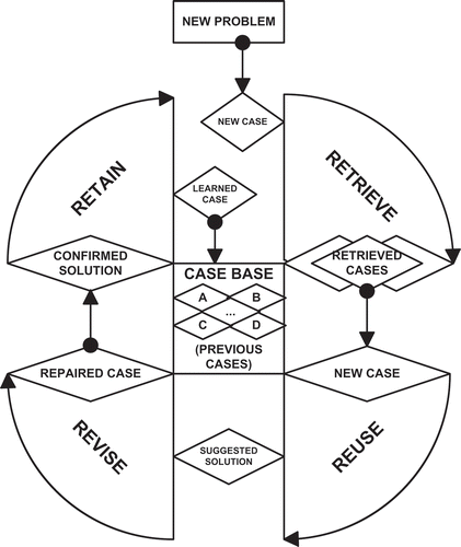
The concept of CBR as a refined AI technique has already been applied successfully in a number of nonengineering fields (Wheeler and Aitken Citation2000; Brüninghaus and Ashley Citation2001; Sai, Shen, and Shen Citation2005; Bichindaritz and Marling Citation2006; Raphael et al. Citation2007; Li and Sun Citation2012; Henriet et al. Citation2014). However, the applications of CBR in engineering domains are relatively fewer (Varma and Roddy Citation1999; Zhang, Deng, and Li Citation2002; Mubarak Citation2004; Negny and Le Lann Citation2008; Janthong, Brissaud, and Butdee Citation2010; Rezvan, Zeinal Hamadani, and Shalbafzadeh Citation2013). As a matter of fact, it is not possible to anticipate every circumstance that a system developed today might encounter. Even if one could, and all the appropriate responses were aggregated, the changing world would soon make that frozen knowledge base obsolete (Craw, Wiratunga, and Rowe Citation2006). The learning process in the CBR takes care of this aspect of changes in a real-world scenario. Similarly, CBR also promises to provide a way to support structural analysis by reminding the analysts of previous experiences that can help them in new situations. Another important advantage of CBR’s flexibility as case base is not tightly bound to the compiled knowledge of rules; rather, it is free to postulate solutions based on less restrictive matching routines. Case-based design enables computers not only to store, retrieve, and present past designs, but also to synthesize design solutions. The issues of representation, indexing, retrieval, and adaptation in application of this sophisticated AI technique during structural engineering have been elaborated in a monograph by researchers (Kumar and Raphael Citation2001). A simple CBR cycle with its four steps—retrieve, reuse, revise, and retain—is shown in .
First, the new problem must be formally described as a case. Then, a similar case to the new problem is retrieved/recalled from the case base (Raphael and Kumar Citation1996). In the next step, the solution of this retrieved case is reused to solve the new problem; in other words, the solution is adapted in order to propose a solution of the problem. The development of an effective knowledge-adaptation technique is a promising solution that performance of the CBR system would improve (Lu, Lu, and Zhang Citation2009). Later, this proposed solution is presented to the user, who can verify and possibly revise it. The revised case is then retained in the case base for future problem solving. The last step realizes the learning phase of a CBR application (Khan, Ming, and Ming Citation1997). The algorithm of a standard CBR process is as follows:
The representation of case is the essence of a CBR system and will determine its effectiveness and smooth operation. Therefore, an appropriate or effective case representation scheme is vital for the CBR system’s functioning and making the reasoning and learning process cost effective.
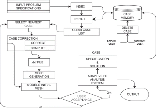
The approach selected by the authors is to overcome the problems discussed with regard to CBR application in the structural analysis domain, using a finite element method. Implementation of CBR principles in the modeling and adaptive finite element analysis process is aimed at reduction of computational burden (Stein Citation2008). In the proposed approach, CBR assists adaptive finite element analysis through selection of an optimum initial mesh from previously solved similar problems. The developed system integrates the intelligent CBR module with an adaptive finite element analysis module in order to achieve the objectives. illustrates the CBR module integration with the adaptive finite element module for development of a robust and intelligent system in this domain.
METHOD
Case Base
A case base or data collection system represents a set of previously solved problems. The representation of cases is the essence of a case-based system, and a representation scheme provides the basis for their use by the system and user. The development of case memory is an ill-defined process that can be as difficult as the knowledge acquisition stage in developing an expert system. The details of case memory determine what the case memory can be used for, how cases can be retrieved, and whether there is enough information for case adaptation. When considering the representation of case memory in the structural domain, three major issues were taken into account for application of CBR:
The content of structural analysis cases,
The representation paradigms for case base organization, and
The presentation of structural analysis cases to the user.
The aspect of determining content for a case base really defines the potentials for use of the system. Case content for this problem domain (i.e., generation of finite element models) includes two parts: problem description and a solution algorithm. Problem description to formulate a complete case for analysis includes the following essential parameters:
Geometrical attributes
Load type and position of application
Boundary conditions
Material and physical data
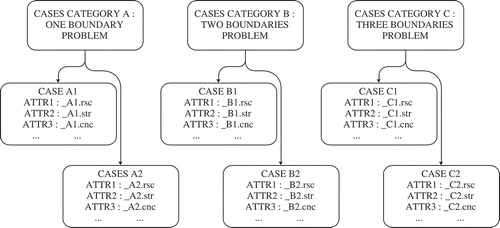
In addition, a complete finite element model or a mesh pattern, information about node connections, element types, and so on are also required in the case base. In order to imply such knowledge, the representation scheme has to be hybrid or complex to encapsulate all the information. To resolve this important aspect, an initial proposal for the knowledge representation scheme using principles of an object-oriented style has been presented by the authors in earlier publications (Khan, Ming, and Ming Citation1997; Khan Citation2001). The case storage in the case base is shown in .
The scheme adopted for case numbering is elaborated in the section “Object-Oriented Representation.” Cases can be added or deleted from the case base, therefore, a file named case.sys has been written to keep track of case numbers available in each category of problems. The assignment of case numbers to new cases and management of the case base by the system is performed strictly in accordance with information in this file.
Nodes Representation
The initial step for defining a case is to represent its topology and mesh distribution. The direct or indirect relationship between the mesh nodes and the boundary nodes are referred to here as node or resource types. Through the analysis of the mesh and topology, all the points are classified into four different classes. The classes of these points are defined as follows:
On Boundary Points. These are the points that define the topology of structure, the points can also be called “edge points.”
On Circle Points. These are the points distributing a circular boundary, which, in order to generate a finite element model, are converted into a goodness curve by a number of line segments. Several points are selected on the circle boundary and connected one by one with the line segments to replace the circle boundary.
Divided on Boundary Points. The mesh nodes located on the boundary where two boundary nodes are already present.
Meshed Points. All those points that do not belong to any of the first three types are placed in this category for representation of knowledge.
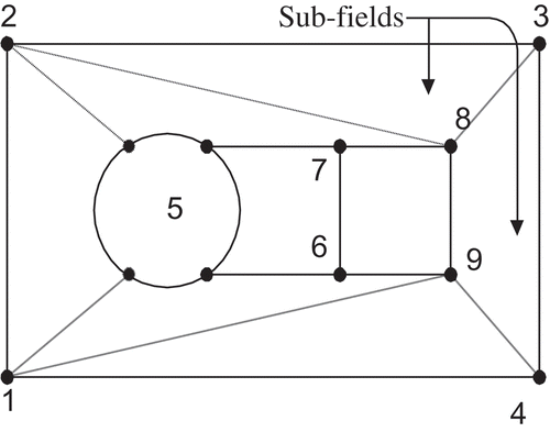
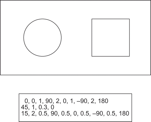
The defined classification assists the system in locating the topology and mesh points on the cases and transferring the same to the corresponding locations of the new problem geometry. The approach is effective for relatively simple geometries. However, the same approach is used in complex geometries through a field-division method, in which complete geometry is considered to be an accumulation of simple geometric shapes. The geometric shape of the structure referred to as a field is divided into subfields with simple geometric shapes that do not have any further holes. In the approach, each subfield is divided into grids by a mapping function, and then all the units of the subfield are joined together. represents the division of a rectangular plate with one circular and one square hole into subfields.
In the proposed approach, the authors have classified the geometric information into resource points, as elaborated previously, to distinguish the nodes in the mesh distribution for a case. Information required to represent each type of points has been tabulated in .
TABLE 1 Resource Point Information
In the table, P, P1, and P2 represent the point coordinates of the resource type; usually these are the end points of the line on which a node is located. The ratio in the table stands for the division by which this point is dividing the line where it is located.
Structure Topology Representation
Connecting the nodes or vertices on the structure topology composes a boundary; these connections between nodes can be a line, arc, or circle connection (if the boundary is circular). Every structure consists of at least one boundary, and in different cases the structure comprises one outer and a number of inner boundaries. If the nodes are connected with lines, the boundary is named a line boundary and if connected with an arc is called an arc boundary. It is called a circular boundary when nodes connected with circles and a mixed boundary when the connections are a mixture of lines and arcs. A boundary is also classified per the number of nodes or vertices it comprises, for example, a square or rectangular structure has a four-node boundary.
Reference length is chosen before representing the boundary numerically in the case. If the boundary is a line boundary, the length of the segment between two node numbers 1 and 2 (line 1-2) is taken as reference, whereas, in the case of a circular boundary, its radius is used as reference length. Once the reference length is selected, its azimuth angle θ is defined as zero. The azimuth angle for other boundaries is the angle formed by the ray and the x-axis; the angle notation is considered as positive for anticlockwise direction. The ray starts from the left lower corner or center in the case of a circle (node number one) and closes at the same node. Lengths of other sides in a boundary are defined as the ratio with the reference length. In addition to all this, the trend angle for every side or line that it makes with the x-axis is also recorded; in the case of a circular boundary, the trend angle of the radius is taken as zero.
The numerical representation for structure topology and the geometric shape in is shown in .
In this case, a three-boundary structure is represented in which the outer boundary is a four-node rectangular plate with a circle and a square as inner boundaries. Numerical representation for this example case includes the trend angle, the ratio of length with respect to the reference length and the radius of the circle. The ratios are computed per Equations (1) and (2).
Geometrical and numerical representation of a three-boundary structure in which the outer boundary is a four-node plate and the inner boundaries are a circle and a square have been represented in . The numerical representation shown in the lower half of the figure includes the trend angle, ratio of length with respect to the reference length for all sides on the boundaries and the radius of circle.
Type of Loading
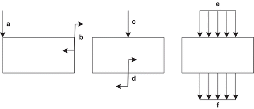
In structural analysis problems, the effect of different loads on the structure is analyzed analytically, experimentally, or through computer simulation. The problem may have different types of loads applied at different positions on the structure. These are generally divided into concentrated, distributed, and moments loads per the position of their application. shows different situations of the application of load on a rectangular plate. The instances a and b in the figure show the concentrated force and moment applied at the boundary nodes or the vertices of the boundary. The instances c and d represent the application of concentrated force and moments at the structure boundary but not at the boundary nodes or the vertices of the boundary as in the earlier case. The instances e and f in show applications of distributed loads on the plate.
Boundary Conditions
In a structural analysis problem, there can be six degrees of freedom that are three forces and three moments. In the devised strategy for boundary condition representation of the case, ‘1’ represents a constraint, whereas ‘0’ represents the free degree of freedom. Therefore, every node in the case has six numbers to describe the complete state of the boundary conditions. shows the boundary conditions for a two-dimensional plate constrained from a side.
Mesh Connectivity Model
A finite element model comprises a number of mesh nodes. In order to infer the useful information from this model, the representation of all the mesh nodes along with their node number, nodal coordinates, and connectivity among nodes is essential. In order to represent this information in the case base, a compound list with one main and a number of sub-branches is used. Each node on the main branch or chain represents a mesh node and is arranged with an ascending number of nodes. The branch lists or subchains under each node show mesh nodes connected directly to the node. If there are two nodes connected directly to the node on the main list and they lie on the same line, they are represented as a side-branch list or subchain. The branch list is perpendicular to the main list, whereas the side-branch lists or lateral subchains are parallel to the main list. depicts information for a two-dimensional rectangular plate meshed into four elements.
Each number in represents a mesh node, and total numbers in the main list are equal to the nodes in the mesh pattern. Branch-list nodes are represented with a diamond shape; these nodes are directly connected to the node on the main list. The node numbers shown in the circle are the side-branch lists. These nodes, although connected directly to the node on the main list, lie on the same line with the main-list node. The data from the input file is transferred into the format of a linked list, which makes it possible to save it in a case base. In this way, the transformation enables the case-based reasoning system to read and utilize the mesh model data effectively. The nodes on the new structure are placed corresponding to their resource type in the existing case. Node coordinates for resource points on a single line depend on the divisions of line and are computed by simple geometric Equations (3) and (4).
Subfield Division
Division of the field is an important aspect of this approach. The first level of partitioning information is stored in the files *.sup (comprises origin of subfield dividing points) and *.suc (connection of subfield dividing points) among the case base contents. The mapping method used in the system has the following requirements for division of the field.
Shape of the subfield must be a quadrilateral or triangle with sides comprising line, conic, and parametric spline curve or arbitrary curve.
Subfield does not have a hole or gap.
Number of subfields may be as small as possible because the fewer the subfields are, the fewer the corresponding mapping functions and, hence, the fewer the calculations of the meshed points.
Quality of the shape of the subfield such as deformity, concave or convex, and so on has no effect on the quality of the mesh produced.
Class Hierarchy
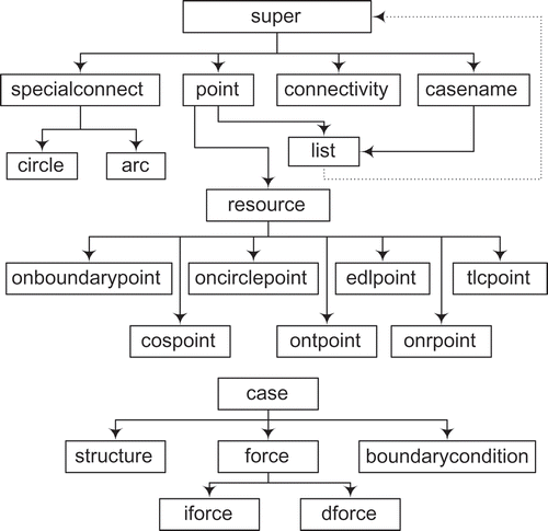
A class hierarchy for the system has been designed to benefit from the basic characteristics of object-oriented programming such as encapsulation and inheritance. These classes realize and implement the case representation strategy discussed thus far. It incorporates all the information essential for finite element analysis. The class identification is done on the basis of a detailed analysis about the relationship among the functions that are required for case representation in case-based reasoning. The candidate classes, shown in are identified and arranged into hierarchies as follows:
| super: | = | The most general class |
| specialconnect: | = | Defining special connections on circle and arc boundaries |
| point: | = | Handling all resources for the points |
| connectivity: | = | Node connectivity for the mesh is defined in this class |
| onboundarypoint: | = | Handles point on the outer boundaries |
| oncirclepoint: | = | Handles point on the circular boundaries |
| edlpoint: | = | Handles equidistant points on the line |
| tlcpoint: | = | Handles point generated by intersection of two lines |
| cospoint: | = | Handles construct point |
| onrpoint: | = | Handles point in rectangular elements, subdividing it into triangles |
| ontpoint: | = | Handles point in triangular element, subdividing it into smaller triangles |
| structure: | = | It is a virtual class with many members for sending/receiving messages from class super |
Object-Oriented Case Representation
The representation of knowledge as a case is a process of determining the contents of the case base and their organization in a structured manner. In the proposed approach, parameters required to define the case are stored in a set of the following six files:
*.rsc Node Resource File
*.cnc Node Connectivity File
*.str Structure Geometry Attributes
*.xyz Node Coordination File
*.sup Subfield Dividing Points File
*.suc Subfield Connections Point
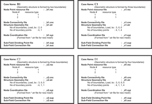
Each case for the proposed system comprises a name and a set of parameters defining attributes in these six files. In the case base, the files are named after the case name with file extensions corresponding to their contents. A typical case for a structure composed of the three geometrical shapes of is shown in as case name “C1.”
The example case is named “C1”; alphabet C stands for a case based on a structure with three geometrical shapes, and number 1 means it is the first case in this category. Based on these guidelines, the organization of different categories of cases in the case base is shown in . Example of case representations “B1,” “C2,” and “D1” in represent problems with two, three, and four geometrical shapes, respectively, whereas the numerical digit in the case names represents that these are first or second cases in this category. Case B1 represents a rectangular plate with a hole inside and it is a first case with a two-boundary category stored in the case base. Case C1 represents a rectangular plate shown in . Case C2 is again a case from the same category, but the rectangular plate has two circular holes. The last case, D1, also represents a rectangular plate with two circular and one square holes.
Six files for representing complete cases in the examples of are named after the case name, and parameters are saved as attribute-value pairs in each file. The cases are indexed by their names in a way that, just by looking at the name of the case, it is obvious to which category it belongs (i.e., structure comprises how many boundaries and sharp edges). This simple classification and organization of cases not only realizes the indexing but also shortens and simplifies the matching process. Thus, the matching or similarity analysis is performed in the similar category of structures.
IMPLEMENTATION AND RESULTS
The importance of an appropriate and effective case representation has been well elaborated and emphasized in the earlier paragraphs. The scheme has already been verified for full implementation along with the remaining essential element of the system. In addition to case representation, indexing, matching, retrieval, and adaptation are also important aspects for development of an effective CBR system. However, development of an adaptive finite element module has its own essentials that are tackled separately before integration. Details of all these vital elements briefly introduced in this article are being published separately.
CONCLUSIONS
The proposed approach is a successful effort toward development of a representation scheme essentially required for CBR application to assist adaptive finite element analysis. The presented scheme of case representation could set the foundation for application of CBR in the automatic-mesh-generation field, an initiator for problem solving in various engineering domains. This will reduce the number of iteration cycles for analysis and provide assistance to the novice user, for whom, at times, problem solving becomes unmanageable. The proposed approach offers a theoretical basis and technical reserves for researchers in the area of specialization for development of an intelligent problem solver. The issues related to indexing, case retrieval, and case adaptation, although worked on for development of an intelligent adaptive finite element analysis system, have not been elaborated in this article. However, the scheme discussed in this article, being an essential aspect for realization of CBR, has been applied to plate problems and verified successfully. The authors believe that continued efforts through further investigation and utilization of the proposed scheme will evolve into a universal integrated structural analysis system for complex aviation structures.
REFERENCES
- Amir, O. 2013. A topology optimization procedure for reinforced concrete structures. Computers & Structures 114:46–58.
- Bargmann, R. 1999. Engineering applications of case-based reasoning. Engineering Applications of Artificial Intelligence 12 (6).
- Behbahani, M., A. Saghaee, and R. Noorossana. 2012. A case-based reasoning system development for statistical process control: Case representation and retrieval. Computers & Industrial Engineering 63(4):1107–1117.
- Bello-Tomás, J. J., P. A. González-Calero, and B. Díaz-Agudo. 2004. Jcolibri: An object-oriented framework for building CBR systems. In Advances in case-based reasoning. Berlin, Heidelberg: Springer-Verlag.
- Bichindaritz, I., and C. Marling. 2006. Case-based reasoning in the health sciences: What’s next? Artificial Intelligence in Medicine 36(2):127–135.
- Bouaanani, N., and F. Y. Lu. 2009. Assessment of potential-based fluid finite elements for seismic analysis of dam-reservoir systems. Computers & Structures 87(3):206–224.
- Brüninghaus, S., and K. D. Ashley. 2001. The role of information extraction for textual CBR. In Case-based reasoning research and development. Berlin, Heidelberg: Springer.
- Cagan, J., and V. Genberg. 1987. Plashtran: an expert consultant on two-dimensional finite element modeling techniques. Engineering with Computers 2(4):199–208.
- Cowan, R. 2001. Expert systems: Aspects of and limitations to the codifiability of knowledge. Research Policy 30(9):1355–1372.
- Craw, S., N. Wiratunga, and R. C. Rowe. 2006. Learning adaptation knowledge to improve case-based reasoning. Artificial Intelligence 170(16–17):1175–1192.
- Dado, M. H. F., and O. A. Shpli. 2003. Crack parameter estimation in structures using finite element modeling. International Journal of Solids and Structures 40(20):5389–5406.
- Díaz-Agudo, B., and P. A. González-Calero. 2000. An architecture for knowledge intensive CBR systems. In Advances in case-based reasoning. Berlin, Heidelberg: Springer.
- Díaz-Agudo, B., P. A. González-Calero, J. A. Recio-García, and A. A. Sánchez-Ruiz-Granados. 2007. Building CBR systems with jcolibri. Science of Computer Programming 69(1):68–75.
- Fang, X., H. Luo, and J. Tang. 2005. Structural damage detection using neural network with learning rate improvement. Computers & Structures 83(25):2150–2161.
- Grant, P. W., P. M. Harris, and L. G. Moseley. 1996. Fault diagnosis for industrial printers using case-based reasoning. Engineering Applications of Artificial Intelligence 9(2):163–173.
- Gregory, B. L., and M. S. Shephard. 1987. The generation of airframe finite element models using an expert system. Engineering with Computers 2(2):65–77.
- Henriet, J., P.-E. Leni, R. Laurent, and M. Salomon. 2014. Case-based reasoning adaptation of numerical representations of human organs by interpolation. Expert Systems with Applications 41(2):260–266.
- Hurley, N. 1994. A case-based reasoning approach to mesh specification for adaptive finite element analysis. Mathematics and Computers in Simulation 36(4):381–388.
- Janthong, N., D. Brissaud, and S. Butdee. 2010. Combining axiomatic design and case-based reasoning in an innovative design methodology of mechatronics products. CIRP Journal of Manufacturing Science and Technology 2(4):226–239.
- Khan, A. A. 2001. Case representation for application of CBR in structural analysis domain. Paper presented at the International Conference on Artificial Intelligence. Las Vegas, Nevada, USA, June 25–28, 2001.
- Khan, A. A., and F. Azam. 2003. CBR assisting computations in structural analysis. Paper presented at Artificial Intelligence and Soft Computing, Banff, Alberta, Canada, July 14–16, 2003.
- Khan, A. A., I. A. Chaudhry, and A. Sarosh. 2014. Case-based reasoning support for adaptive finite element analysis: Mesh selection for an integrated system. Applied Physics Research 6(3):19.
- Khan, A. A., X. Y. Ming, and W. X. Ming. 1997. Knowledge representation in case-based reasoning for finite element analysis. Paper presented at the 2nd Asian Pacific Conference on Aerospace Technology and Science (APCAT ’97). Dun Huang Gansu, China, October 6–10, 1997.
- Khan, A. A., X. Y. Ming, and S. Zhang. 1997. Case-based approach for mesh specification in adaptive finite element analysis. Paper presented at the 4th IFAC Workshop on Intelligent Manufacturing System (IMS ’97). Seoul, Korea, July 21–23, 1997.
- Khoshgoftaar, T. M., N. Seliya, and N. Sundaresh. 2006. An empirical study of predicting software faults with case-based reasoning. Software Quality Journal 14(2):85–111.
- Kocsis, T., S. Negny, P. Floquet, X. Meyer, and E. Rév. 2014. Case-based reasoning system for mathematical modeling options and resolution methods for production scheduling problems: Case representation, acquisition and retrieval. Computers & Industrial Engineering 1/2014 (77):46–64.
- Kullaa, J. 2011. Distinguishing between sensor fault, structural damage, and environmental or operational effects in structural health monitoring. Mechanical Systems and Signal Processing 25(8):2976–2989.
- Kumar, B., and B. Raphael. 1997. Cadrem: A case-based system for conceptual structural design. Engineering with Computers 13(3):153–164.
- Kumar, B., and B. Raphael. 2001. Derivational analogy based structural design: London, UK: Saxe-Coburg.
- Labrie, R., C. Thilloy, P. A. Tanguy, and G. H. Moll. 1994. An expert assistant to monitor finite element simulations. Mathematics and Computers in Simulation 36(4):413–422.
- Lee, C. K., and S. H. Lo. 1994. A new scheme for the generation of a graded quadrilateral mesh. Computers & Structures 52(5):847–857.
- Li, H., and J. Sun. 2012. Case-based reasoning ensemble and business application: A computational approach from multiple case representations driven by randomness. Expert Systems with Applications 39(3):3298–3310.
- Lu, N., J. Lu, and G. Zhang. 2009. An integrated knowledge adaption framework for case-based reasoning systems. In Knowledge-based and intelligent information and engineering systems, LNAI. Berlin, Heidelberg: Springer-Verlag.
- Lu, Y., Q. Li, and W. Xiao. 2013. Case-based reasoning for automated safety risk analysis on subway operation: Case representation and retrieval. Safety Science 57:75–81.
- Mubarak, K. 2004. Case-based reasoning for design composition in architecture (PhD thesis, School of Architecture, Carnegie Mellon University, Pittsburgh, PA, USA).
- Negny, S., and J. M. Le Lann. 2008. Case-based reasoning for chemical engineering design. Chemical Engineering Research and Design 86(6):648–658.
- Raphael, B., B. Domer, S. Saitta, and I. F. C. Smith. 2007. Incremental development of CBR strategies for computing project cost probabilities. Advanced Engineering Informatics 21(3):311–321.
- Raphael, B., and B. Kumar. 1996. Indexing and retrieval of cases in a case-based design system. Artificial Intelligence for Engineering, Design, Analysis and Manufacturing 10(1):47–63.
- Reynier, M. 1986. Interactions between structural analysis, know-how and chain of reasoning used by the carter expert system for dimensioning. Reliability of methods for engineering analysis, 533–544. Swansea, UK: Pineridge Press.
- Rezvan, M. T., A. Z. Hamadani, and A. Shalbafzadeh. 2013. Case-based reasoning for classification in the mixed data sets employing the compound distance methods. Engineering Applications of Artificial Intelligence 26(9):2001–2009.
- Sai, J., X. Shen, and C. Shen. 2005. Application of CBR retrieval method to weather forecast based on rough set. Computer Engineering and Design 26(11):2898–2901.
- Sriram, D., M. L. Maher, and S. J. Fenves. 1985. Knowledge-based expert systems in structural design. Computers & Structures 20(1):1–9.
- Stein, B. 2008. Model construction for knowledge-intensive engineering tasks. In Advances
- Taig, I. C. 1986. Expert aids to reliable use of finite element analysis. Applications of artificial intelligence to engineering problems, ed. D. Sriram and R. Adey. Berlin, Heidelberg: Springer-Verlag, 1986.
- Varma, A., and N. Roddy. 1999. Icarus: design and deployment of a case-based reasoning system for locomotive diagnostics. Engineering Applications of Artificial Intelligence 12(6):681–690.
- Venkatasubramanian, V., R. Rengaswamy, S. N. Kavuri, and K. Yin. 2003. A review of process fault detection and diagnosis: Part III: Process history based methods. Computers & Chemical Engineering 27(3):327–346.
- Vong, C.-M., P.-K. Wong, and W.-F. Ip. 2011. Case-based expert system using wavelet packet transform and kernel-based feature manipulation for engine ignition system diagnosis. Engineering Applications of Artificial Intelligence 24(7):1281–1294.
- Wheeler, R., and S. Aitken. 2000. Multiple algorithms for fraud detection. Knowledge-Based Systems 13(2):93–99.
- Yan, A., H. Shao, and Z. Guo. 2014. Weight optimization for case-based reasoning using membrane computing. Information Sciences 287:109–120.
- Yaonan, G., and X. Yuanming. 1995. Femes: Expert system for finite element modeling. Journal of Mechanical Strength 2.
- Yeung, C. L., C. F. Cheung, W. M. Wang, and E. Tsui. 2014. A knowledge extraction and representation system for narrative analysis in the construction industry. Expert Systems with Applications 41(13):5710–5722.
- Zhang, G., G. Deng, and Z. Li. 2002. Prospectus and technologies used in CBR. Computer Engineering and Applications 20:52–55.

