
Abstract
In augmented reality, the markers are noticeable by their simple design of a rectangular image with black and white areas that disturb the reality of the overall view. As the markerless techniques are not usually robust enough, hiding the markers has a valuable usage, which many researchers have focused on. Categorizing the marker hiding methods is the main motivation of this study, which explains each of them in detail and discusses the advantages and shortcomings of each. The main ideas, enhancements, and future works of the well-known techniques are also comprehensively summarized and analyzed in depth. The main goal of this study is to provide researchers who are interested in markerless or hiding-marker methods an easier approach for choosing the method that is best suited to their aims. This work reviews the different methods that hide the augmented reality marker by using information from its surrounding area. These methods have considerable differences in their smooth continuation of the textures that hide the marker area as well as their performance to hide the augmented reality marker in real time. It is also hoped that our analysis helps researchers find solutions to the drawbacks of each method.
INTRODUCTION
Augmented reality is a real-world environment that has computer-generated virtual objects overlaying accurately real elements that allow the user to interact with it in real time (Furhut Citation2011). In the augmented reality application, the camera is used for capturing the image and then the virtual objects are augmented on top of the image using a tracking module for calculating the correct orientation of the overlaid virtual objects and a rendering module that combines the image and the virtual objects (Siltanen Citation2012). This generated virtual information can range from 3D objects to simple notes about the objects in the scene.
The augmented reality applications are either fiducial systems that use markers or nonfiducial systems that are markerless. In general, markers share a design of rectangular black and white patterns nearly similar to the patterns used by the ARToolkit (Citationn.d.), which is the most common toolkit for developing augmented reality applications. The marker-based augmented reality applications have broad usage due to their standardization, and they can enable high frame rate compared to markerless-based augmented reality applications (Kato and Billinghurst Citation1999; Elarbi-Boudihir, Rehman, and Saba Citation2011; Rehman and Saba Citation2014). Moreover, using the markers is the simplest way to estimate the camera pose in the tracking module (Siltanen Citation2012; Rubio 2006; Rehman and Saba Citation2012; Rahim et al. Citation2011; Haron et al. Citation2011).
The key issue in developing augmented reality applications is the user experience, which can be affected by several aspects such as the performance, interaction, content creation, and visual perception (Siltanen Citation2012) The visual perception may be enhanced by augmented reality systems through multiple ways such as using different rendering techniques and hiding the augmented reality marker. The rendering techniques can be photorealistic (Aittala Citation2010; Pessoa et al. Citation2010; Kolivand, Noh, and Sunar Citation2013; Haron et al. Citation2012; Rahim et al. Citation2011) or non-photorealistic rendering (Lerotic et al. Citation2007; Chen, Turk, and MacIntyre Citation2012) according to the purpose of the application. However, the augmented reality marker can be hidden by using invisible markers (Nakazato, Kanbara, and Yokoya Citation2005; Wang, Liu, and Wang Citation2008; Muhsin et al. Citation2014) or by using the surrounding background information of the marker as an approach to using the diminished reality, which is the main focus of this article.
Hiding the augmented reality marker can be considered a significant factor that can ensure the realistic views that enhance the visual perception, which can directly affect the user experience. Hiding the augmented reality marker from the final image can have a valuable usage in several fields such as education, especially for children, because there will be no visual disturbance by the presence of the marker. In addition, the hidden marker in game-based augmented reality will support the “realness” of the graphics of the game. There are many other augmented reality applications that can be positively affected by hiding the marker, such as in the fields of advertisement, sales, and architecture design.
For developing marker-based augmented reality applications, the marker needs to follow certain guidelines for easier tracking and detection even under luminance variations. These guidelines involve the marker image, border, background, and their arrangement. To facilitate the marker detection, black and white markers are usually the optimal to be used because of their contrast in the luminance (Siltanen Citation2012; Norouzi et al. Citation2014).
The marker is preferred to be a square because it is the simplest shape needed to acquire the four required points for the calculation of the camera pose (Hartley and Zisserman Citation2003). Additionally, the four corners of the square are easily estimated as the intersections of the edge lines (Siltanen Citation2012). The marker should have a black border that is double the size of the marker image. The border thickness should be one quadrant of the marker thickness and the inner part of the marker is for the marker image, which is half the thickness of the marker, as shown in . The border is used for marker detection; therefore, the marker image should not be extended into the border, and the border should be in the first place and of opposing color to the background.
FIGURE 1 Augmented reality markers.

By using these guidelines, the system can use multiple markers that can have different interactions, which is one of the features that makes the marker-based applications more flexible than the markerless-based applications.
This design of the black and white marker makes it remarkable to the observer’s vision while using the marker-based augmented reality application. Accordingly, the presence of the marker in the final image does not allow the smooth merging of the real-world environment and the virtual objects that overlay the marker area. As a result, the existence of the marker hinders the reality of the overall view and may not be suitable for using in some applications that rely on the realistic view of the final image.
In order to resolve this problem and achieve a realistic view in marker-based augmented reality applications as well as benefit from the usage of the marker, the marker should be hidden from the final image. Hiding the marker depends primarily on the background that the marker is laid on, which could be a textured or nontextured background.
For the nontextured background, the marker can be hidden simply by using one or more colors that are sampled from the marker surrounding area (Siltanen and Woodward Citation2006; Mundher et al. Citation2014). This simple method of using only some colors cannot be suitable for the augmented reality environment because the background of the marker is usually more complex and textured.
For the textured background, the information from the marker’s neighboring area should be used to generate texture that can hide the marker area, which is the technique of digital image inpainting. The digital image inpainting approaches are designed to fill in lost or corrupted regions by copying and repeating pixels from the neighboring area (Bertalmío et al. Citation2000). The inpainting technique has found widespread usage in several applications, such as object removal from images and hiding writings on photographs. The region that needs to be inpainted is referred to as a hole, and it can be provided in the form of a mask.
The core intention of the inpainting technique is to fill in a hole in such a way that the inpainted region becomes undetectable to a neutral observer. The inpainting approaches are varying in the quality of the inpainted area; some approaches focus only on preserving the image texture (Efros and Freeman Citation2001; Harrison Citation2001) or preserving only the linear structures (Tschumperlé Citation2006; Bornemann and März Citation2007), whereas others try to combine both texture generation and structure reconstruction (Waykule Citation2013; Anupam, Goyal, and Diwakar Citation2010; Yining Deng and Manjunath Citation2001; Sangeetha, Sengottuvelan, and Balamurugan Citation2011; Neamah et al. Citation2014; Rehman and Saba Citation2014). Generally, each inpainting approach has its weakness and strength, which is reflected in the final result of the inpainted area.
Another key factor in the inpainting process is the processing time, which can be counted in seconds (Kokaram Citation2002) or even in minutes (Bertalmío Citation2000). However, the inpainting technique is used mainly for offline applications and still images processing and is not directly suitable for using in real-time applications. However, there are several attempts to use the inpainting technique in real time. This can be done by using the inpainting result for every frame as one of the diminished reality techniques.
In contrast to the concept of augmented reality, which is adding virtual objects to the real environment, diminished reality allows the virtual removal of objects from the real environment (Herling and Broll Citation2010). In other words, augmented reality and diminished reality are considered as dissimilar areas of mixed reality, as can be shown in . In , from left to right, the reality–virtuality environment axis and the middle contain all the groupings that form the mixed environment (Prince et al. Citation2002; Cheok et al. Citation2006; Dubois, Gray, and Nigay n.d.).
FIGURE 2 Mediated reality taxonomy (adapted from Siltanen Citation2012).
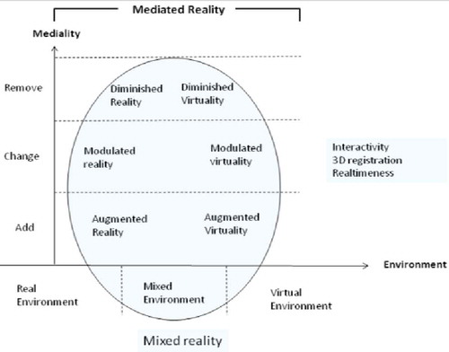
In diminished reality, an object can be removed from the image by using the actual background of the image, which can be performed by any of several methods (Enomoto and Saito Citation2007; Jarusirisawad, Hosokawa, and Saito Citation2010; Zokai et al. Citation2003) that use multiple cameras or by using the previous frames in a video sequence (Lepetit, Berger, and Lorraine Citation2001) to capture the background. Another technique for object removal in diminished reality is to generate a background from the information surrounding the object, using the image inpainting approaches that will be focused on in this article.
Based on the concept of using the inpainting technique for real-time diminishing, there are multiple methods that use different techniques of image inpainting to hide the augmented reality marker, which will be reviewed in this article. These methods have considerable differentiation in the computational load, overall performance, and the geometric stability between consecutive frames to avoid flickering problems.
Besides the processing time and the quality of the inpainted area, there are some factors that can influence on the final image of the hidden marker, such as the effect of the shadow, especially in outdoor applications (Kolivand and Sunar Citation2013a,b), and the lighting variation in the case of using a moving camera.
TIMELINE IN HIDING MARKER METHODS
Hiding the augmented reality marker can be considered a new field of research that has limited methods that are used to hide the marker in real time. Despite the fact that these methods are relatively recent, there is a considerable progression in the quality of the texture that is used to hide the marker area along with enhancing the overall performance. However, there are still multiple improvements that are needed in order to use these methods under different conditions while maintaining a high performance and preserving the quality of the generated texture for the hidden area.
As can be seen in , in 2006 a method for hiding the marker area by using its neighborhood texture was presented (Siltanen Citation2006) as one of the first attempts for hiding the augmented reality marker. In 2007, a different method was proposed that constructs alternative images that hide the marker in real time based on patch-based texture synthesis (Kyungdahm and Woontack Citation2007).
FIGURE 3 Hiding marker timeline.
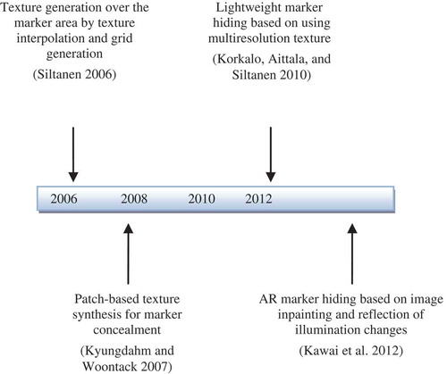
Afterward, another method based on using multiresolution texture to reflect the global illumination changes as well as improving the performance was presented in 2010 (Korkalo, Aittala, and Siltanen Citation2010).
In 2012, a different method was proposed (Kawai Citation2012) that was based on the diminished reality technique that uses image inpainting to generate textures on objects rather than using a real background texture to overlay the object regions. In this method, both global and local illumination changes are reflected to the generated texture that hides the marker area. These methods will be reviewed in detail in the next section, except the method proposed in Kyungdahm and Woontack (Citation2007), which is written in the Korean language and poses a translation conflict.
DIFFERENT METHODS OF HIDING THE MARKER
The methods that hide the augmented reality marker can be categorized into two categories according to their technique of applying the generated texture that hides the marker area in real time.
The first category is periodic texture generation-based methods, which are the methods that generate texture for every frame or even every certain number of frames. The second category is unique texture generation-based methods, which are the methods that generate a texture only once in the first frame, according to the camera pose estimation, and apply it to the following frames; they also reflect the illumination changes in these frames. These categorized methods are described in details as follows.
Periodic Texture Generation-Based Methods
A method for generating a texture for hiding the marker in augmented reality applications was presented in Siltanen (Citation2006). In this method, a texture is generated by a simple technique using the interpolation of the neighborhood of the detected marker area. Additionally, the texture interpolation is combined with grid generation. In this method, there are some assumptions that have to be taken into consideration. First, it is assumed that the marker is not placed on the edge of the surface that is laid on, which implies that the marker is placed on the center section. Also, there is an assumption about the neighboring background of the marker area that is the same as the one covered by the marker. Based on these assumptions, the surrounding pixels will be contrarily proportional to their distance to the marker border.
For texture generation, the texture outside the border of the marker on each side fades into the other side of the border by mirroring it onto the inside. The texture is generated for the area between the detected marker (including the white border around the marker, which is assumed to have a known size) and a larger square size where the marker is centered. Hence, the texture is generated for a hidden area that is bigger than the marker, as can be seen in .
FIGURE 4 The marker area for texture generation (adapted from Siltanen Citation2006).
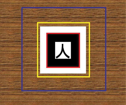
In , the area of the detected marker, which is the black and white rectangular pattern, is surrounded by the red square, and the yellow square specifies the area that will be covered with the generated texture that is larger than the marker area. The area that will be used for texture generation is the area between the blue and the yellow squares.
For using this method in real-time applications, two techniques are described (Siltanen Citation2006). First, the texture is generated using the first frame and then the generated texture is applied in the following frames, which is the same concept as that of the second category of methods (Korkalo, Aittala, and Siltanen Citation2010; Kawai et al. Citation2012). Moreover, to overcome the varying lighting conditions, the generated texture is partly transparent near the edges, and this transparent part covers the real background outside the marker, which is the area between the white border of the marker and the yellow square in .
The second technique for the real-time usage as described in this method (Siltanen Citation2006) is based on generating texture for every frame. Additionally, to achieve better performance, according to the uncommon lighting variations in successive frames, the whole texture can be updated within a certain number of seconds instead of updating the whole texture in every frame. Hence, the required processing time per frame for updating the texture within 5 seconds on a frame rate of 25 fps will be only 1/125 of the time needed for updating the whole texture, which significantly improves the performance.
The required time for the texture generation in this method is considerably fast, and the quality of the hidden area is acceptable when the pattern size of the texture is smaller than the marker area and the background is smooth and simple, as shown in .
FIGURE 5 Texture generation over the marker area for small pattern size (adapted from Siltanen Citation2006).
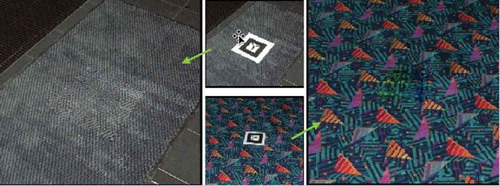
Also, the area that is used for the texture generation, which is bigger than the detected marker area, ensures better merging of the generated texture and the background.
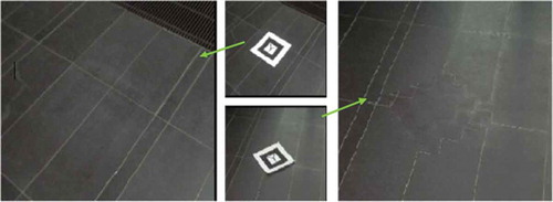
On the contrary, when the pattern size of the texture is quite larger than the marker area, or if it has an irregular pattern, this method may not generate appropriate results. Similarly, for complex textured backgrounds or in some cases that have multiple linear structures, the generated texture that covers the marker area becomes noticeable, as shown in . Moreover, the assumptions of the marker position and the background that the marker is laid on can limit the use of the marker on an edge of the surface because the area that will be used for texture generation will not be accurate. Also, if the marker is covering more than one object, which means that the covered background has many texture patterns, the result of the generated texture will not accurately reflect the background that is covered by the marker.
FIGURE 6 Texture generation over the marker area that has multiple structure lines (adapted from Siltanen Citation2006).
Unique Texture Generation-Based Methods
Lightweight Marker Hiding
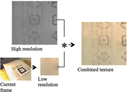
Another method for hiding the augmented reality marker was presented in Korkalo, Aittala, and Siltanen (Citation2010) as a lightweight method for generating and updating rectangular texture patches to hide the marker area. This method focuses mainly on using a multiresolution texture that can respond to the changing surroundings as well as increase the performance. In this method, image inpainting is used to generate a high-resolution texture the first time the marker is detected, so it requires to be computed only once. Then, for each consequent frame, the former texture patch is updated using a lower-resolution texture that can be acquired in real time. A sample of high- and low-resolution textures is shown in .
FIGURE 7 An overview of the method used in Korkalo, Aittala, and Siltanen (Citation2010). (Adapted from Korkalo, Aittala, and Siltanen Citation2010.)
An enhanced version of the previous method in Yining Deng and Manjunath (Citation2001), is used for the high-resolution texture generation. However, for the low-resolution texture, the colors of the texture boundary pixel are read from the matching rectangle surrounding the marker. The value of the inner points of the texture is computed by the average of its four neighbors in several iterations. In order to avoid possible flickering, the color values of the edge are sampled as averages or medians from various pixels, which also may be averaged in time by updating the edge values using only half the value of the new color at each frame.
The static high-resolution texture that was generated in the first frame is combined in every frame with the changing low-resolution texture by multiplying them in the rendering phase. In order to avoid repeating the same components that are represented in the high and low resolutions, the high-resolution texture is extracted from these components.
This extraction is performed at the initial generation by dividing the high-resolution texture by its corresponding low-resolution texture. Then, the values are divided by two to ensure that the colors that are brighter than the average colors are not lost. The high-resolution texture is then adapted to the current conditions after the texture normalization is done, which sets the boundary color values to gray.
This method has made significant progress in hiding the augmented reality marker because the low-resolution texture can represent the variations in the global illumination, and it does not require long processing time to generate the low-resolution texture and update the high-resolution texture. However, it still poses several challenges when being used under varied conditions such as in moving the camera around the marker; the low-resolution texture in that case cannot signify the variations visibly because it can represent only the global luminance changes. As a result, merging the unclear low-resolution texture, in that case, with the high-resolution one that has not been updated might produce blurring texture background.
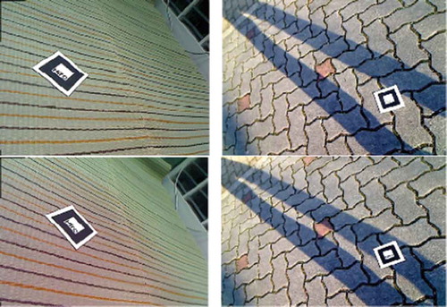
Some results of applying this method are shown in . From left to right in the upper row, the original image and using only high-resolution texture to hide the marker is shown. In the lower row from left to right, a nonupdated texture and high-resolution texture merged with low-resolution texture to hide the marker is shown.
FIGURE 8 Lightweight marker hiding (adapted from Korkalo, Aittala, and Siltanen Citation2010).
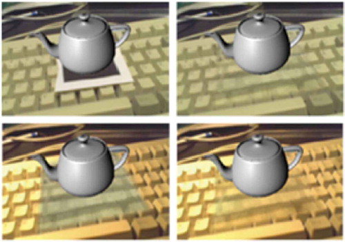
Image Inpainting and Illumination Changes Reflection for Marker Hiding
A new method was proposed that focuses on the diminished reality technique, which generates textures on objects by image inpainting instead of overlaying a real background texture onto the object regions (Kawai et al. Citation2013). This method has been used to hide the augmented reality marker based on the previous work in Kawai et al. (Citation2012), which uses the exemplar-based inpainting method to inpaint the marker region.
In general, the exemplar-based inpainting method can combine the linear structure reconstruction and texture synthesis for higher quality and enhanced result of the inpainted area. An arbitrary exemplar-based inpainting method using global optimization as in Wexler, Shechtman, and Irani (Citation2007) and the image inpainting method with brightness consideration in Kawai, Sato, and Yokoya (Citation2009) are appropriate to use in this method of hiding the augmented reality marker (Kawai et al. Citation2013).
Generally, there are three main aspects that are considered in this method, with the aim of natural marker hiding. These aspects are the naturalness of the generated texture, geometric consistency between successive frames, and photometric consistency between the marker area and its neighboring area. To achieve the naturalness of the generated texture that will hide the marker area, the exemplar-based inpainting technique is used along with correction of the perspective distortion.
The inpainting process is used only in the first frame to generate the texture instead of inpainting for every frame, in order to ensure the geometric consistency, and then the generated texture is overlaid on the marker area according to the camera pose. Because the luminance changes can affect the final result of the inpainted area to seem unnatural, both global and local luminance changes are detected to adjust the luminance of the inpainted marker area, which results in geometric and photometric consistency. An example of the global and local luminance changes is shown in ; from left to right, the global changes and the local changes.
FIGURE 9 Types of luminance changes (adapted from Kawai et al. Citation2013).
There are two main processes described previously in the literature (Kawai et al. Citation2013). The first process is to generate texture by image inpainting of the marker area. The second process is to hide the marker by overlaying the generated texture over the marker area and to reflect the luminance changes for every frame. The two processes of this method perform in parallel to speed up the performance. The first process is applied only for the first frame after correction of the perspective distortion, which is performed by the second process. By using an homography matrix, the perspective distortion is corrected to unify the shape and size of the texture pattern. The second process is responsible for the adjustment of the luminance of the inpainted marker area, which ensures the photometric consistency.
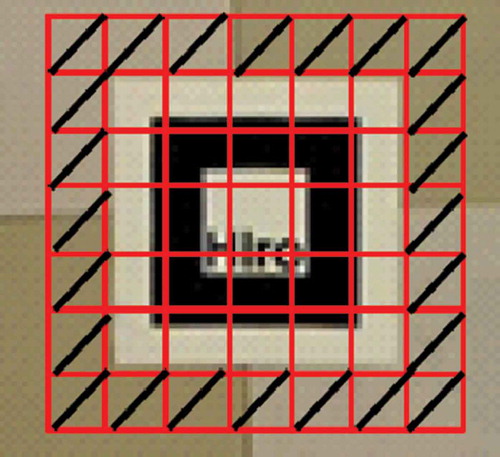
The local luminance changes are detected by cast shadows, whereas the global luminance changes are detected by ambient illumination changes and camera parameter changes. In these detection phases, the marker area is divided into regular grids as shown in ; each pixel will be classified into shadow regions and nonshadow regions. Due to the photometric difference between the marker and its surrounding area, the amplitude of luminance changes is estimated from the area surrounding the marker instead of the marker area.
FIGURE 10 Divided grids (adapted from Kawai et al. Citation2013).
In the phase of detection and reflection of the luminance changes, the cast shadows are detected in the area around the marker. If cast shadows exist around the marker, an interpolation is performed in shadow regions in the marker region and local luminance changes are calculated. In the case of the absence of cast shadows in the area around the marker, only the global luminance changes are calculated. The final generated texture is overlaid on the marker area using an inverse matrix of homography, and then the values of the pixels in the target region of the marker area of the image converted by the homography matrix are copied to the original image pixels.
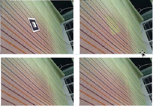
A major advance has been achieved by this method: the improved quality of the inpainted area that overlies the marker region, which seems to be natural and smooth according to the correction of the perspective distortion and the reflection of the luminance changes. However, there are some negative aspects to this method. First, the perspective distortion is corrected based on an assumption that the surface that the marker is laid on is planar, which might conflict or generate undesired results if the area around the marker is nonplanar. Second, although the quality of the inpainted area is highly enhanced, the calculations needed for detecting the local and global luminance changes and their reflection on the hidden marker area, as well as the correction of the perspective distortion, could affect the computational load and the overall performance. A sample of the result using this method is shown in : from left to right in the upper row, the input image and the marker hidden without reflection of luminance changes; in the lower row from left to right, reflecting only global luminance changes and reflecting both local and global luminance changes to the hidden marker area.
FIGURE 11 Reflection of luminance changes (adapted from Kawai et al. Citation2013).
DISCUSSION
The discussed methods are apparently aimed to enhance the quality of the hidden marker area as well as improve the performance of hiding the marker in real time. From the results of these methods, it can be perceived, generally, that enhancing the quality of the inpainted area that overlies the marker region can affect adversely the required time to execute the method, because the relation between the quality of the final image of a hidden marker and the effectiveness of hiding the marker in real time are usually contrary to each other.
The periodically generated texture in the first category can signify the variations clearly in multiple conditions, however, that periodic generation can affect the performance of the method. The unique generated texture in the second category can support the improvement of the performance. However, updating this unique generated texture might not significantly represent the inconstancy in some cases (such as moving camera and lighting variations), or it might affect the computational load to generate a high-quality inpainted area. A comparison of the two categories is represented in .
TABLE 1 Comparison of the Categories of Marker-Hiding Methods
CONCLUSION
Hiding the augmented reality marker is becoming an essential aspect of the realistic view in marker-based augmented reality applications. In this article, the existing methods for hiding the augmented reality marker are categorized into two categories according to their technique of applying them in real time. The first category focuses on periodic texture generation that hides the marker area for every frame. The second category is for generating a unique texture in the first frame according to the camera pose and applying it to the consequent frames along with reflection of illumination changes. The core focus of these methods is the quality of the generated texture that covers the marker area along with the performance of applying it for the real-time marker-based augmented reality applications. To accomplish better results for hiding the augmented reality marker in real time, the performance needs to be more optimized and multiple aspects should be considered, such as the lighting variations under moving camera and the various types of shadows that can exist around the marker area and the smoothness of the surface that the marker is laid on. Future development will probably focus on how to balance the performance with the quality of the inpainted area under different variations and will also consider more complex backgrounds.
FUNDING
The authors extend their appreciation to the Deanship of Scientific Research at King Saud University for funding this work through research group no. RGP-264.
Additional information
Funding
REFERENCES
- Aittala, M. 2010. Inverse lighting and photorealistic rendering for augmented reality. The Visual Computer 26(6–8):669–678.
- Anupam, P. Goyal, and S. Diwakar. 2010. Fast and enhanced algorithm for exemplar based image inpainting. In Fourth Pacific-Rim symposium on image and video technology (PSIVT 2010), 325–330. USA: IEEE Computer Society.
- ARToolKit. n.d. Retrieved from http://www.hitl.washington.edu/artoolkit/
- Bertalmío, M., G. Sapiro, V. Caselles, and C. Ballester. 2000. Image inpainting. In Proceedings of 27th annual conference on computer graphics and interactive techniques (SIGGRAPH 2000), 417–424. New York, NY, USA: ACM Press.
- Bornemann, F., and T. März. 2007. Fast image inpainting based on coherence transport. Journal of Mathematical Imaging and Vision 28(3):259–278.
- Chen, J., G. Turk, and B. MacIntyre. 2012. A non-photorealistic rendering framework with temporal coherence for augmented reality. In Proceedings of the IEEE and ACM international symposium on mixed and augmented reality (ISMAR 2012),151–160. USA: IEEE Computer Society.
- Cheok, A. D., K. S. Teh, T. H. D. Nguyen, T. C. T. Qui, S. P. Lee, W. Liu, C. C. Li, D. Diaz, and C. Boj. 2006. Social and physical interactive paradigms for mixed-reality entertainment. Computers in Entertainment 4(2):5.
- Efros, A., and W. T. Freeman. 2001. Image quilting for texture synthesis and transfer. In Proceedings of ACM conference computer graphics (SIGGRAPH 2001), 341–346. New York, NY, USA: ACM Press.
- Elarbi-Boudihir, M., A. Rehman, and T. Saba. 2011. Video motion perception using operation Gabor filter. International Journal of Physical Sciences 6(12):2799–2806.
- Enomoto, A., and H. Saito. 2007. Diminished reality using multiple handheld cameras. In Proceedings of the workshop on multidimensional and multi-view image processing (ACCV 2007), 130–135. Berlin, Heidelberg: Springer.
- Furhut, B. (Ed.). 2011. Handbook of augmented reality. New York, NY, USA: Springer.
- Haron, H., A. Rehman, D. I. S. Adi, S. P. Lim, and T. Saba. 2012. Parameterization method on b-spline curve. Mathematical Problems in Engineering Volume 2012, Article ID 640472.
- Haron, H., A. Rehman, L. A. Wulandhari, and T. Saba. 2011. Improved vertex chain code based mapping algorithm for curve length estimation. Journal of Computer Science 7(5):736–743.
- Harrison, P. 2001. A non-hierarchical procedure for re-synthesis of complex texture. Paper presented at the Winter School of Computer Graphics Conference, 190–197. Plzen, Czech Republic, February 5–9.
- Hartley, R., and A. Zisserman. 2003. Multiple view geometry in computer vision. New York, NY, USA: Cambridge University Press.
- Herling, J., and W. Broll. 2010. Advanced self-contained object removal for realizing real-time diminished reality in unconstrained environments. In Proceedings of the 9th IEEE international symposium on mixed and augmented reality (ISMAR 2010), 207–212. USA: IEEE.
- Jarusirisawad, S., T. Hosokawa, and H. Saito. 2010. Diminished reality using plane- sweep algorithm with weakly-calibrated cameras. Journal of Progress in Informatics 7(1):11–20.
- Kato, H., and M. Billinghurst. 1999. Marker tracking and HMD calibration for a video-based augmented reality conferencing system. In Proceedings of the 2nd IEEE and ACM international workshop on augmented reality (IWAR ‘99), 85–94). Los Alamitos, CA, USA: IEEE Computer Society.
- Kawai, N., T. Sato, and N. Yokoya. 2009. Image inpainting considering brightness change and spatial locality of textures and its evaluation. In Proceedings of the 3rd Pacific-Rim symposium on advances in image and video technology (PSIVT 2009), 271–282. Berlin, Heidelberg: Springer.
- Kawai, N., M. Yamasaki, T. Sato, and N. Yokoya. 2012. AR marker hiding based on image inpainting and reflection of illumination changes. In Proceedings of the 11th IEEE and ACM international symposium on mixed and augmented reality (ISMAR 2012), 293–294. USA: IEEE Computer Society.
- Kawai, N., M. Yamasaki, T. Sato, and N. Yokoya. 2013. Diminished reality for ar marker hiding based on image inpainting with reflection of luminance changes. ITE Transactions on Media Technology and Applications 1(4):343–353.
- Khoo, E. T., T. Merritt, and A. D. Cheok. 2010. In Designing a mixed reality intergenerational entertainment system, ed. E. Dubois, P. Gray, and L. Nigay, 121–141. London: Springer.
- Kokaram, A. 2002. Parametric texture synthesis for filling holes in pictures. In Proceedings of the international conference on image processing, 325–328. USA: IEEE.
- Kolivand, H., Z. Noh, and M. S. Sunar. 2013. A quadratic spline approximation using detail multi-layer for soft shadow generation in augmented reality. Multimedia Tools and Applications 73(3):1225–1245.
- Kolivand, H., and M. S. Sunar. 2013a. Covering photo-realistic properties of outdoor components with the effects of sky color in mixed reality. Multimedia Tools and Applications 72(3):2143–2162.
- Kolivand, H., and M. S. Sunar. 2013b. A survey on volume shadows in computer graphics. IETE Technical Review 30(1):38–46.
- Korkalo, O., M. Aittala, and S. Siltanen. 2010. Light-weight marker hiding for augmented reality. In Proceedings of the 9th IEEE international symposium on mixed and augmented reality (ISMAR 2010), 247–248. USA: IEEE.
- Kyungdahm, Y., and W. Woontack. 2007. Patch-based texture synthesis for marker concealment. Journal of the HCI Society of Korea 2(2):11–18.
- Lepetit, V., M.-O. Berger, and L.-I. Lorraine. 2001. An intuitive tool for outlining objects in video sequences: Applications to augmented and diminished reality. In Proceedings of the second international symposium on mixed reality (ISMR 2001), 159–160. USA: IEEE.
- Lerotic, M., A. J. Chung, G. Mylonas, and G.-Z. Yang. 2007. pq-space based non- photorealistic rendering for augmented reality. In Proceedings of the 10th international conference on medical image computing and computer-assisted intervention, eds. N. Ayache, S. Ourselin, and A. J. Maeder, 102–109. Berlin, Heidelberg: Springer.
- Muhsin, Z. F., A. Rehman, A. Altameem, T. Saba, and M. Uddin. 2014. Improved quadtree image segmentation approach to region information. The Imaging Science Journal 62(1):56–62.
- Mundher, M., D. Muhamad, A. Rehman, T. Saba, and F. Kausar. 2014. Digital watermarking for images security using discrete slantlet transform. Applied Mathematics and Information Sciences 8(6):2823–2830.
- Nakazato, Y., M. Kanbara, and N. Yokoya. 2005. Wearable augmented reality system using invisible visual markers and an ir camera. In Proceedings of the ninth IEEE international symposium on wearable computers (ISWC 2005), 198–199. Los Alamitos, CA, USA: IEEE Computer Society.
- Neamah, K., D. Mohamad, T. Saba, and A. Rehman. 2014. Discriminative features mining for offline handwritten signature verification. Journal of 3D Research 5(1):2.
- Norouzi, A., M. S. M. Rahim, A. Altameem, T. Saba, A. E. Rada, A. Rehman, and M. Uddin. 2014. Medical image segmentation methods, algorithms, and applications. IETE Technical Review 31(3):199–213.
- Pessoa, S., G. Moura, J. Lima, V. Teichrieb, and J. Kelner. 2010. Photorealistic rendering for augmented reality: A global illumination and BRDF solution. In Proceedings of the IEEE virtual reality conference (IEEE VR2010), ed. B. Lok, G. Klinker, and R. Nakatsu, 3–10. USA: IEEE.
- Prince, S., A. D. Cheok, F. Farbiz, T. Williamson, N. Johnson, M. Billinghurst, and H. Kato. 2002. 3-D live: Real time interaction for mixed reality. In Proceedings of the ACM conference on computer supported cooperative work (CSCW 2002), ed. E. F. Churchill, J. F. McCarthy, C. Neuwirth, and T. Rodden, 364–371. New York, NY, USA: ACM.
- Rahim, M. S. M., A. Rehman, M. F. A. Jabal, and T. Saba. 2011. Close spanning tree (cst) approach for error detection and correction for 2d cad drawing. International Journal of Academic Research 3(4):525–533.
- Rehman, A. and T. Saba. 2012. Evaluation of artificial intelligent techniques to secure information in enterprises. Artificial Intelligence Review 42(4):1029–1044.
- Rehman, A. and T. Saba. 2014. Neural network for document image preprocessing. Artificial Intelligence Review 42(2):253–273.
- Rehman, A., and T. Saba. 2014. Features extraction for soccer video semantic analysis: Current achievements and remaining issues. Artificial Intelligence Review 41(3): 451–461.
- Rubio, M., A. Quintana, H. Pérez-Rosés, R. Quirós, and E. Camahort. 2006. Jittering reduction in marker-based augmented reality systems. In Proceedings of the 6th international conference on computational science and its applications (ICCSA 2006), eds. M. L. Gavrilova, O. Gervasi, V. Kumar, C. J. K. Tan, D. Taniar, A. Laganà, Y. Mun, and H. Choo, 510–517. Berlin, Heidelberg: Springer.
- Sangeetha, K., P. Sengottuvelan, and E. Balamurugan. 2011. Combined structure and texture image inpainting algorithm for natural scene image completion. Journal of Information Engineering and Applications 1(1):7–12.
- Siltanen, S. 2006. Texture generation over the marker area. In Proceedings of the 5th IEEE and ACM international symposium on mixed and augmented reality (ISMAR 2006), 253–254. Washington, DC: IEEE Computer Society.
- Siltanen, S. 2012. Theory and applications of marker-based augmented reality. Espoo, Finland: VTT.
- Siltanen, S., and C. Woodward. 2006. Augmented interiors with digital camera images. In Proceedings of the seventh Australasian user interface conference (AUIC 2006), ed. W. Piekarski, 33–36. Darlinghurst, Australia: Australian Computer Society.
- Tschumperlé, D. 2006. Fast anisotropic smoothing of multi-valued images using curvature-preserving PDE’s. International Journal of Computer Vision 68(1):65–82.
- Wang, T., Y. Liu, and Y. Wang. 2008. Infrared marker-based augmented reality system for equipment maintenance. In Proceedings of the 2008 international conference on computer science and software engineering (CSSE 2008), 816–819. Los Alamitos, CA, USA: IEEE Computer Society.
- Waykule, J. M. 2013. Modified image exemplar-based inpainting. International Journal of Advanced Research in Computer and Communication Engineering 2(9):3734–3740.
- Wexler, Y., E. Shechtman, and M. Irani. 2007. Space-time completion of video. IEEE Transactions on Pattern Analysis and Machine Intelligence 29(3):463–476.
- Yining Deng and B. S. Manjunath. 2001. Unsupervised segmentation of color-texture regions in images and video. IEEE Transactions on Pattern Analysis and Machine Intelligence 23(8):800–810.
- Zokai, S., J. Esteve, Y. Genc, and N. Navab. 2003. Multiview paraperspective projection model for diminished reality. Proceedings of the international symposium on mixed and augmented reality (ISMAR 2003), 217–226. Washington, DC: IEEE Computer Society.