
ABSTRACT
High frequency (HF) transformer at the isolation stage of SST plays a vital role in deciding the power conversion efficiency of the SST system. This paper proposes a new design procedure for optimization of HF transformer used in SST applications such that it fulfils all the requirements pertaining to its operating conditions. The novel design procedure proposed is based on optimizing the core geometry (in 5th power of cm), which has direct influence on regulation and copper loss. An isolated half-bridge DC–DC converter topology is chosen for implementing the proposed design. Four bio-inspired algorithms, namely Particle swarm optimization (PSO), Whale Optimization algorithm (WOA), Dragonfly Algorithm (DA), and Ant Lion Optimizer (ALO) are used to solve the optimization problem and the results are compared with Genetic algorithm (GA). Finally, the optimization results are validated through PowerEsim, a web-based testing platform with huge database of real-time components from leading manufacturers across the globe.
Introduction
The evolution of Solid State Transformer (SST) in recent years as a promising new class of grid assets can be attributed to their ability to offer service extensions beyond voltage transformation, such as provision for dual power output (both dc and ac), input–output decoupling, high switching frequency, fault isolation, better power quality, etc. The heart of the SST system is the high frequency (HF) isolated dc–dc converter, which provides galvanic isolation between the medium voltage AC grid and a low voltage AC/DC grid as shown in . Though the choice of HF results in reduced footprint for the transformer, it also leads to higher switching losses and saturation of magnetic components. Further, the reduction in footprint entails an increased loss density in the transformer, which necessitates significant efforts on thermal management (Meier et al. Citation2009). Thus a robust design procedure is required which collectively addresses the HF, isolation and thermal management issues and yields desired efficiency concurrently retaining the %regulation and power losses within specified limits.
Figure 1. Basic three stage SST architecture.
Numerous high/medium frequency transformer design solutions for various applications were established in literature. Earlier, researchers have attempted to develop detailed HF transformer design for switching power supplies (Coonrod Citation1986; McLyman Colonel Citation1993; Pressman Citation1998; Rama Rao et al. Citation2004). The design considerations of medium frequency transformers for railway traction applications were discussed in literature in the previous decade (Kjellqvist, Norrga, and Ostlund Citation2004; Steiner and Reinold Citation2007). The design optimization of high/medium frequency transformers for DC offshore applications was also documented in the past (Bahmani Citation2014; Bahmani, Thiringer, and Kharezy Citation2015). Research efforts on design of high/medium frequency transformers for SST applications have been widely reported in literature (Du et al. Citation2010; Huina, Xiaodong, and Gang Citation2012; Ortiz et al. Citation2013; She et al. Citation2014; Montoya, Mallela, and Balda Citation2015).
Further, a thorough survey of literature reveals that research contribution toward HF transformer design have come in the way of optimizing the core based on area product (Farhangi and Akmal Citation1999; McLyman Citation1993), optimizing the flux density of the core and current density of the windings (Petkov Citation1996), optimization including HF effects (Hurley, Wolfle, and Breslin Citation1998), optimization with arbitrary current and voltage waveforms (Breslin, Citation2002), high isolation requirements and thermal management (Ortiz, Biela, and Kolar Citation2010), minimizing the losses taking leakage inductance and phase shifted angle of the converter into consideration (Hoang and Wang Citation2012), optimization with emphasis on thermal and insulation design (Peng and Jurgen Citation2013) and maximizing the power density by accounting for tuned leakage inductance (Bahmani M.A. Citation2014; Bahmani M.A. et al. Citation2015).
All the aforementioned research efforts focus on either single or multi-objective optimization with or without single/multiple constraints with a procedure involving verification of bounds for parameter values other than constraints before arriving at an optimal solution to the problem. This is a time-consuming process as every time an operating parameter is found to infringe the bounds, the optimization algorithm searches for another optimal solution satisfying the bounds.
This paper is intended to present a simple, yet robust optimization procedure for the design of HF transformer based on core geometry coefficient (defined by McLyman Citation1993) with a constraint imposed on its specific loss. The proposed procedure circumvents the verification of parametric limits for producing an optimal solution as the optimal core geometry (in 5th power of cm) directly brings all the operating parameters like %regulation and temperature rise within preferred limits without compromising on efficiency. Moreover, the proposed procedure is less time consuming than the methods documented in literature as it does not involve verification loops for bounds on operating parameters. Above all, in contrast to other methods where attention need to be paid to avoid saturation effects on magnetic components, the proposed optimization does not have this issue as the core selection is made only after obtaining the optimal core geometry.
The proposed optimization is executed on an isolated half-bridge dc–dc converter with few of the latest bio-inspired algorithms, which are proved to be highly efficient compared with GA. The results of optimization are validated through PowerEsim which unlike other simulation tools is built with practical power supply modules and components from leading manufacturers in the market (Poon Citation2009).
Isolated half bridge DC–DC converter
A number of dc–dc converter topologies for SST applications have been investigated in the past (Kolar and Ortiz Citation2014; Shri Citation2013) and their relative merits and demerits discussed. Since the primary objective here is the design optimization of HF transformer, a simple half bridge dc–dc converter topology is chosen for unidirectional and Modular SST applications. However, the design optimization can be carried out with any dc–dc converter topology that is deemed appropriate for a particular application.
shows the basic converter schematic and the associated waveforms of a half-bridge isolated dc–dc converter. The element for energy transfer is the leakage inductance of the transformer. The switches S1 and S2 are turned on with a phase shift of 180° and both experience a voltage stress equal to that of the input voltage, in contrast to twice the input voltage as in push–pull and forward converters (Vinnikov, Jalakas, and Egorov Citation2008). Also, the magnetization of the isolation transformer is bidirectional and hence there is no need for a demagnetizing circuit. Other advantages of this converter include less primary turns for the same input voltage and power, lesser winding costs, lower proximity effect losses, no danger of transformer saturation, reduced cost, and its ability to be scaled up to higher power levels.
Figure 2. Schematic of isolated half-bridge converter and its associated waveforms.
The apparent power of the transformer in a half bridge converter is calculated as follows:
Secondary apparent power for tapped winding,
where Vo and Io are output voltage and current respectively and Vd is the diode voltage drop.
Primary apparent power,
Thus, total apparent power
The d.c. transfer function of the half bridge converter is derived as
Design optimization
Procedure
While most of the proposed design methodologies for HF transformers were based on a specified temperature rise, they can also be designed for a given %regulation, “α”. As per definition by (McLyman Citation1993), α is associated with two coefficients namely, the electrical coefficient “Ke” and the core geometry coefficient “Kg” given by
where Kf is the waveform coefficient, Pt is the total apparent power in Watts, f is the operating frequency in Hz, and Bm is the flux density in tesla.
Alternately, Kg can be expressed as
where Wa is the window area in cm2, Ac is the effective core cross-section in cm2, Ku is the window utilization factor, and MLT is the mean length of the turn in cm.
From Equations (6) and (7), it is noted that Kg not only influences the size of the magnetic components but also affects the regulation and copper loss. Thus by optimizing Kg, it is possible to design a transformer, which is more compact and efficient, simultaneously holding the other key design requirements like %regulation, current density in the windings, copper losses, temperature rise etc., within specified bounds.
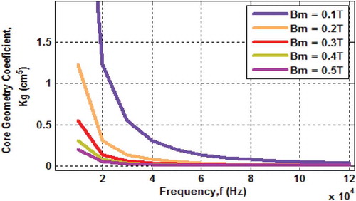
Referring to Equations (5) and (6), it is clear that Kg is a function of two variables namely, f and Bm with fixed %regulation. Though flux density in the core is actually a function of operating frequency, a good trade-off is needed between these two parameters such that optimum core geometry is achieved. Therefore, while optimizing Kg, frequency and flux density are chosen as the free parameters. The variation of core geometry coefficient with operating frequency and flux density is depicted in .
Figure 3. Plot of core geometry coefficient with frequency.
The optimization problem in general is stated mathematically as follows:
Find X = [X(1) X(2)…X(n)], such that F = f(X) is minimum subject to
Ximin < X(i) < Ximax where i = 1,2…n and Ci (X) < 0, i = 1,2,…m,
where X(1), X(2),……X(n) represent the set of independent design variables with Ximin and Ximax as their lower and upper bounds respectively. F = f(X) is the objective function to be optimized and Ci(X) are the design constraints.
Minimize Kg such that
(i) fmin < f < fmax
(ii) Bmmin < Bm < fmmax
with the constraint Wpk (f,Bm) – 0.05*Pt <0†
where Wpk is the specific loss in W/Kg and Pt is the total apparent power in watts.
† Specific loss is assumed to be limited to 5% of total apparent power.
With f and Bm chosen as two independent design variables and Kg as the objective function to be minimized with a constraint imposed on the specific loss of the transformer, the design problem can now be stated as follows.
The design flowchart for the proposed optimization procedure is depicted in . The design equations are presented in the Appendix. The inputs to the design problem are power output and voltage levels of the converter. Efficiency and regulation in percentage, waveform coefficient and window utilization factor are chosen to be the fixed parameters. Contrary to the design of low frequency transformer where V/f is held constant to avoid over-fluxing, the operating frequency here is swept across specified limits along with maximum flux density as the choice of core and its dimensions are made only after establishing the optimum core geometry.
Figure 4. Flowchart for the proposed design optimization of high frequency transformer.
Once the best values for the free parameters are found and the optimal value for core geometry coefficient is established using latest bio-inspired algorithms, suitable core material is selected from the core data table corresponding to the optimal value. If there is no precise match for the optimal core geometry coefficient from the core data table, then the core with next higher value for Kg is chosen to ensure minimal copper loss.
The dimensions of the selected core and their specifications are extracted from the table. With these dimensions and specifications, the current density in the windings, number of turns in the primary and secondary are calculated. The primary and secondary wire areas are then calculated and a wire size with the required wire area is found from the wire table. Subsequently, primary and secondary winding resistances and hence copper losses are calculated. The new values for %regulation and flux density are then updated. The core losses and hence the total losses are calculated followed by the power density and temperature rise.
The design specifications of a single converter module are considered for evaluating the test cases presented in of this paper. Several such modules can be connected in parallel at the low voltage side (LVDC link) and in series at the high/medium voltage side (HVDC/MVDC link) as per requirement.
Table 1. Design specifications of a single converter module.
Algorithms for optimization
Nature-inspired optimization algorithms are being extensively applied nowadays to solve real and complex engineering design problems (Yang Citation2010). Earlier, GA has been widely applied to solve transformer design optimization problems (Coonrod Citation1986; Rama Rao et al. Citation2004; Yadav et al. Citation2011; Versèle, Deblecker, and Lobry Citation2012). However, more recently Artificial Bee Colony (ABC) and PSO algorithms have been employed to solve these problems (Davood, Mehdi, and Jawad Citation2016).
In this paper, Particle Swarm Optimization (PSO) algorithm along with three other recently developed algorithms namely, Ant Lion Optimizer (ALO), Dragon Fly Algorithm (DA), and Whale Optimization Algorithm (WOA) are applied to solve the proposed optimization problem and the results are compared with the conventional GA. The proposed optimization procedure is more simple and straight forward than the methods presented in the literature cited above.
The Ant Lion optimizer
This algorithm emulates the natural hunting behavior of antlions by modeling the interactions between antlions and ants in the trap (Mirjalili Citation2015). The stages involved in hunting process viz., random walk of ants, building traps, entrapment of ants in traps, catching preys, and re-building traps are modeled mathematically. The pseudocode for the algorithm along with a detailed analysis is presented in the reference cited above.
Dragon fly algorithm
This algorithm is inspired by the static (hunting) and dynamic (migration) swarming behavior of dragon flies in nature (Mirjalili, S. Citation2016b). The collective interaction of dragonflies in traversing, hunting for prey, and evading enemies are modeled as two vital stages of optimization: exploration and exploitation. Random values within specified bounds of variables are used to initialize the position and step vectors of dragon flies which are then updated iteratively until the required criterion is met.
Whale optimization algorithm
The social hunting behavior of humpback whales is used to model this algorithm (Mirjalili, S. Citation2016a). The three steps involved in the hunting process by Whales namely, tracking the prey, encircling the prey, and the bubble-net feeding behavior are modeled mathematically in order to perform optimization.
Optimization results and discussion
Three test cases are evaluated in support of the proposed optimization procedure and the design specifications for the same are listed in . A single module isolated half-bridge dc–dc converter is chosen for validating the test cases. For modular SST applications, a number of such modules can be cascaded as per requirements. Since the output power of half-bridge converter is limited to 750 W, the test cases are chosen accordingly. However, with higher end dc-dc converters, the power levels can be extended beyond 1 kW. The fixed parameters assumed for all the case studies are common and are presented in .
Table 2. Fixed parameters for optimization.
The operating frequency, f and the maximum flux density, Bm which influence the core geometry coefficient (Equations (5) and (6)) are chosen as the free parameters. They are swept over a wide range within specified bounds to find the best optimal value for Kg. The limits for the operating frequency are set between 10 and 120 kHz and that for the maximum flux density between 0.1 and 0.6 T. The upper boundary for flux density is usually set by the saturation flux density of the core material with a safety margin of 10–20% to avoid operation close to saturation. For the case studies considered in this paper, ferrite core is chosen as they have lower core losses (above 20 kHz) and are available in a wide variety of geometric shapes. The maximum value for saturation flux density of ferrite core is 0.45 T. Therefore, the upper limit for Bm is fixed at 0.6T.
Upon optimization using PSO, ALO, DA, and WOA, the best values for free parameters and the optimal core geometry are established. A comparison of performance of all the algorithms with GA for the three test cases is presented in . All the four nature-inspired algorithms are compared on the basis of identical search agents (equal to 100). The computational speed and the number of iterations for convergence are averaged over 10 successive runs. For the case studies under consideration, it is discerned from the table that all the algorithms return identical optimal solution though they differ in computational speed and convergence. With less number of generations, the optimal value generated by GA is inconsistent in successive runs. However, with an initial population of 200 and increase in number of generations to 1000, GA produces a consistent solution at the cost of increased overall computational time.
Table 3. Comparison of performance of optimization algorithms.
The core data pertaining to the optimal value of Kg are listed in . For all the three test cases, the core having a Kg value slightly higher than the optimum Kg is selected. This is done to ensure minimal copper loss. The look up table for the core data is created with the details obtained from the leading magnetic component suppliers, Magnetics®. presents the electric, magnetic, and geometric characteristics of the transformer calculated from the optimal core data.
Table 4. Optimal core data.
Table 5. Optimal transformer characteristics.
It is inferred from that the design optimization procedure based on core geometry coefficient proposed in this paper is effective in solving the HF transformer design problem in a simple, yet efficient manner while keeping all the operational parameters like % regulation, temperature rise and system losses within desired limits. Though all the algorithms used for solving the proposed design problem produce the same optimal values for the parameters under consideration, a comparative analysis shows that they differ with respect to speed of convergence, consistency in producing solutions in successive runs, and the speed of computation.
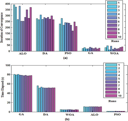
shows the convergence of the optimization algorithms plotted for Test Case II. This comparison is based on identical population size and equal number of search agents for all the algorithms except GA. As can be seen from the plot, WOA has high speed of convergence followed by PSO, DA, and ALO. However, referring to ), it is clear that among the nature-inspired algorithms, DA is more consistent in producing the optimal results in successive runs. Another interesting fact to be noted is that though WOA is quick to converge compared to PSO algorithm, the relative computational time is the least with PSO (less than a couple of seconds) as portrayed in ). This is because the computational time per iteration is the least with the PSO algorithm.
Figure 5. Convergence plot of the optimization algorithms.
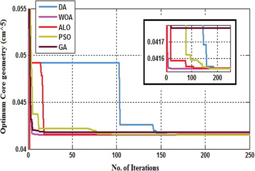
Figure 6. (a) Convergence plot in successive runs. (b) Time plot of convergence in successive runs.
Design validation and results
The proposed design optimization for HF transformers has been tested using PowerEsim, a web-based result-oriented design tool for power converters and transformers (Poon Citation2009). Unlike traditional tools, PowerEsim is developed using real-world power supplies and components with due consideration to industrial demands and regulations. As such, it is not a simulation tool but a testing tool used by design engineers and trainees from leading industries across the world to verify and improvise their design.
The design validation of the proposed optimization procedure is carried out for one of the test cases (Test Case II) by selecting a half-bridge converter from the available database in PowerEsim. The implemented schematic and the power circuit component specifications are shown in and , respectively. The Mean Time Between Failure (MTBF) analysis for the overall converter circuit is displayed in and that for the HF transformer is depicted in . The switching waveforms and performance charts presented in reveal the efficiency of the circuit and regulation to be 92.79% and 0.5%, respectively. presents the winding arrangement of the HF transformer. From , it can be seen that the choice of core by PowerEsim tool is a double slab ferrite core with part no. DS43019, similar to the one chosen by the optimization algorithms. However, for the same test case, the choice of the core is HF-5835 with a circuit efficiency as low as 78% using analytical method. This serves as a valid proof for the success of the proposed design optimization procedure for HF transformers in Modular SST applications where regulation and efficiency are considered vital parameters in the design.
Figure 7. Schematic of the half-bridge DC–DC converter implemented in PowerEsim.
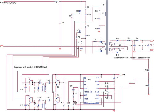
Figure 8. (a) Output switching ripple voltage waveform. (b) Input voltage (CH1) and input current (CH2) waveforms. (c) %Efficiency vs. input voltage. (d) Total dissipated losses vs. input voltage. (e) Output voltage regulation. (f) Variation of peak flux density of the transformer with respect to input voltage.
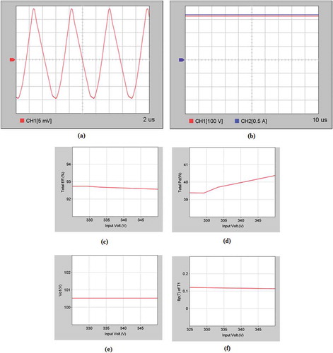
Figure 9. Winding arrangement of HF transformer.
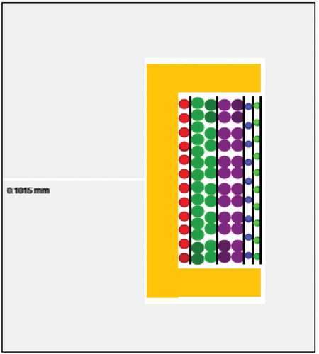
Figure 10. HF transformer design with PowerEsim.
Table 6. Specifications of power circuit components.
Table 7. MTBF analysis of the overall circuit.
Table 8. MTBF analysis of the HF Transformer.
Conclusion
This paper has attempted to present a simple, single-objective design optimization procedure for HF transformers used in modular SST applications. The objective was to optimize the core geometry coefficient with a constraint placed on specific loss such that the design produces a compact and efficient HF transformer with all performance parameters under preferred limits. Four latest nature-inspired algorithms were engaged to accomplish the proposed optimization task and the results compared with GA. It was found that WOA exhibited quick convergence whereas PSO offered best overall performance with respect to convergence and computational time. The proposed optimization procedure was implemented using PowerEsim, a real-time design tool as well and the results were found to be satisfactory.
The highlights of the research work are listed below
This paper is a maiden attempt to optimize the HF transformer based on core geometry (in 5th power of cm) with a constraint imposed on its specific loss keeping regulation and temperature rise within limits in addition to preserving desired efficiency.
Further, the proposed optimization procedure avoids the need for verification of bounds for parameter values as the optimal value established for core geometry directly brings all the operating parameters within desired limits without compromising on efficiency. Additionally, in contrast to other methods where attention need to be paid to avoid saturation effects on magnetic components, the proposed optimization does not have this issue as the core selection is made only after obtaining the optimal core geometry.
Three recently developed optimization algorithms namely, Whale Optimization algorithm (WOA), Dragonfly Algorithm (DA), and Ant Lion Optimizer (ALO), which have not been applied to transformer design so far are compared with GA and PSO for their efficacy in solving the optimization problem with respect to various parameters.
Finally, the optimization results are validated through PowerEsim, a web-based testing platform with huge database of real-time components from leading manufacturers across the globe.
Related Research Data
References
- Bahmani, M. A. 2014. Design and optimization of hf transformers for high power DC-DC applications. Goteborg, Sweden: Chalmers Reproservice.
- Bahmani, M. A., T. Thiringer, and M. Kharezy. 2015. Design methodology and optimization of a medium frequency transformer for high power DC-DC applications. Applied Power Electronics Conference and Exposition (APEC), IEEE, Charlotte, NC, USA, pp. 2532–39.
- Breslin, J. G. 2002. Optimisation of high frequency transformer design with arbitrary current and voltage waveforms. PhD. diss., National University of Ireland, Galway. doi:10.1044/1059-0889(2002/er01).
- Coonrod, N. R. 1986. Transformer computer design aid for higher frequency switching power supplies. IEEE Transactions on Power Electronics 1 (4):248–56. doi:10.1109/TPEL.1986.4766317.
- Davood, A., B. Mehdi, and F. Jawad. 2016. Design optimization of cast-resin transformer using nature-inspired algorithms. Arabian Journal for Science and Engineering 41 (9): 3491–500.
- Du, Y., B. Seunghun, B. Subhashish, and A. Q. Huang. 2010. High-voltage high-frequency transformer design for a 7.2kV to 120V/240V 20kVA Solid State Transformer. Paper presented at the 36th Annual Conference on IEEE Industrial Electronics Society (IECON), Glendale, AZ, USA.
- Farhangi, S., and A. Akmal. 1999. A simple and efficient optimization routine for design of high frequency power transformers. Paper presented at the 9th EPE Conference, Graz, Austria.
- Hoang, K. D., and J. Wang. 2012. Design optimization of high frequency transformer for dual active bridge DC-DC converter. Paper presented at the XXth International Conference on Electrical Machines, IEEE, Marseille, France, pp.2311–17.
- Huina, Y., W. Xiaodong, and W. Gang. 2012. Design of electronic transformer used in a proposed circuit topology for PET. Paper presented at the Power and Energy Engineering Conference (APPEEC), IEEE, Shangai, China, pp.1–4.
- Hurley, W. G., W. H. Wolfle, and J. G. Breslin. 1998. Optimized transformer design: Inclusive of high-frequency effects. IEEE Transactions on Power Electronics 13 (4):651–59. doi:10.1109/63.704133.
- Kjellqvist, T., S. Norrga, and S. Ostlund. 2004. Design considerations for a medium frequency transformer in a line side power conversion system. Paper presented at the 35th Annual IEEE Power Electronics Specialists Conference, IEEE, Aachen, Germany.
- Kolar, J. W., and G. Ortiz. 2014. Solid-state-transformers: Key components of future traction and smart grid systems. Proceedings of the International Power Electronics Conference-ECCE Asia (IPEC), pp. 18–21.
- McLyman Colonel, W. T. 1993. Designing magnetic components for high frequency DC-DC converters. USA: Kg Magnetics Inc.
- Meier, S., T. Kjellqvist, S. Norrga, and H. P. Nee. 2009. Design considerations for medium-frequency power transformers in offshore wind farms. IEEE 13th European Conference on Power electronics and applications EPE, Barcelona, Spain. 1–12.
- Mirjalili, S. 2015. The Ant Lion Optimizer. Advances in Engineering Software, Elsevier Publishers 83:80–98. doi:10.1016/j.advengsoft.2015.01.010.
- Mirjalili, S. 2016a. The whale optimization algorithm. Advances in Engineering Software, Elsevier Publishers 95:51–67. doi:10.1016/j.advengsoft.2016.01.008.
- Mirjalili, S. 2016b. Dragonfly algorithm: A new meta-heuristic optimization technique for solving single- objective, discrete, and multi-objective problems. Neural Computing and Applications 27 (4):1053–73. doi:10.1007/s00521-015-1920-1.
- Montoya, R. J. G., A. Mallela, and J. C. Balda. 2015. An evaluation of selected solid-state transformer topologies for electric distribution systems. Applied Power Electronics Conference and Exposition (APEC), IEEE, Charlotte, NC, USA, pp. 1022–29.
- Ortiz, G., J. Biela, and J. W. Kolar. 2010. Optimized design of medium frequency transformers with high isolation requirements. Paper presented at the 36th Annual Conference on IEEE Industrial Electronics Society (IECON), Glendale, AZ, USA.
- Ortiz, G., M. Leibl, J. W. Kolar, and O. Apeldoorn. 2013. Medium frequency transformers for solid-state-transformer applications - design and experimental verification. Paper presented at the 10th IEEE International Conference on Power Electronics and Drive Systems (PEDS), Kitakyushu, pp. 1285–90.
- Peng, S., and B. Jurgen. 2013. Design and optimization of medium frequency, medium voltage transformers. Paper presented at the 15th European Conference on Power Electronics and Applications (EPE), IEEE, Lille, France, pp.1–10.
- Petkov, R. 1996. Optimum design of a High-Power, High-Frequency transformer. IEEE Transactions on Power Electronics 11 (1):33–42. doi:10.1109/63.484414.
- Poon, N. K. 2009. PowerEsim-free on-line result oriented design tool. Paper presented at the 3rd International Conference on Power Electronics Systems and Applications, IEEE, Hong Kong, China.
- Pressman, A. I. 1998. Switching power supply design. 2nd ed., McGraw-Hill, USA.
- Rama Rao, K. S., Y. L. Lai, T. Soib., and S. Masri. 2004. Design optimization of a high frequency power transformer for a switching power supply by genetic algorithms approach. Open access repository of USM Research and Publication.
- She, X., Y. Xunwei, W. Fei, and A. Q. Huang. 2014. Design and demonstration of a 3.6-kV–120-V/10-kVA solid-state transformer for smart grid application. IEEE Transactions on Power Electronics 29 (8):3982–96. doi:10.1109/TPEL.2013.2293471.
- Shri, A. 2013. A solid-state transformer for interconnection between the medium- and the low-voltage grid design. Master of Science Thesis Report, Delft University of Technology, Netherlands.
- Steiner, M., and H. Reinold. 2007. Medium frequency topology in railway applications. Paper presented at the European Conference on Power Electronics and Applications, IEEE, Aalborg, Denmark.
- Versèle, C., O. Deblecker, and J. Lobry. 2012. A computer‐aided design tool dedicated to isolated DC‐DC converters based on multiobjective optimization using genetic algorithms. COMPEL - the International Journal for Computation and Mathematics in Electrical and Electronic Engineering 31 (2):583–603. doi:10.1108/03321641211200590.
- Vinnikov, D., T. Jalakas, and M. Egorov. 2008. Feasibility study of half- and full-bridge isolated DC/DC converters in High-Voltage High-Power applications. Paper presented at the 13thPower Electronics and Motion Control Conference, EPE-PEMC, Poznan, Poland.
- Yadav, A. K., O. P. Rahi, H. Malik, and A. Azeem. 2011. Design optimization of high-frequency power transformer by genetic algorithm and simulated annealing. International Journal of Electrical and Computer Engineering (IJECE) 1 (2):102–09. doi:10.11591/ijece.v1i2.88.
- Yang, X.-S. 2010. Nature-inspired meta heuristic algorithms. 2nd ed. UK: Luniver Press.
Appendix
Maximum Duty ratio,
where T is the total time period and tdw is the dwell time (1 µs)
Secondary load power for single winding in Watts,
Secondary load power for tapped winding in Watts,
Total Apparent Power in Watts,
Average primary current in amps,
(for half-bridge converter)
Average primary voltage in Volts,
where Rq is the on resistance of transistor in Ohms
Primary turns,
Current density in amps/cm2,
Primary rms current in amps,
Primary wire area in cm2,
Skin Depth in cm,
Wire area in cm2,
Primary winding resistance in Ohms,
Primary copper loss in Watts,
Secondary turns on each side of center tap,
Secondary wire area in cm2,
No. of strands required,
Secondary winding resistance in ohms,
Secondary copper loss in Watts,
Total copper loss in Watts,
Window utilization factor,
Regulation in %,
Flux Density in Tesla,
Watts per kilogram,
Core loss in Watts,
Total Losses in Watts,
Watt density in Watts/cm2,