
 ?Mathematical formulae have been encoded as MathML and are displayed in this HTML version using MathJax in order to improve their display. Uncheck the box to turn MathJax off. This feature requires Javascript. Click on a formula to zoom.
ABSTRACT
The high-precision navigation and positioning ability of UAV (Unmanned Aerial Vehicles) is the key factor to reflect its degree of automation. Visual navigation based on image matching has become one of the important research fields for UAV to realize autonomous navigation, because of its low cost, strong anti-jamming ability, and good location result. However, the visual quality of images captured by UAV will be seriously affected by some factors, such as weak illumination conditions or insufficient performance of its sensors. Resolving a series of degradation of low-light images can improve the visual quality and enhance the performance of UAV visual navigation. In this paper, we propose a novel fully convolutional network based on the Retinex theory to solve the degradations of low-light images captured by UAV, which can improve the visual quality of the images and visual matching performance effectively. At the same time, a visual navigation system is designed based on the proposed network. Extensive experiments demonstrate that our method outperforms the existing methods by a large margin both quantitatively and qualitatively, and effectively improves the performance of the image matching algorithms. The visual navigation system can successfully realize the self-localization of UAV under different illumination conditions. Moreover, we also prove that our method is also effective in other practical tasks (e.g. autonomous driving).
Introduction
To realize long-term autonomous flight, UAV(Unmanned Aerial Vehicles) need an autonomous navigation and positioning system with high precision. At present, the navigation system of UAV mainly includes Global Navigation Satellite System (GNSS), Inertial Navigation System (INS), Radio Navigation System (RNS), and so on. The GNSS includes the GPS of America, the GLONASS of Russia, the Galileo of Europe, and the BDS of China(Dong (Dong and Department Citation2017)). The GNSS has a great advantage in location accuracy and the error will not accumulate over time. However, the disadvantage is poor autonomy, it is easy to be disturbed by external factors. Therefore, it can not meet the needs of high-precision positioning in some scenarios; once the UAV loses the signal due to external interference, it will not be able to accomplish the mission.
With the rapid development of computer vision and artificial intelligence technology, a new navigation method, visual navigation, has emerged. Visual navigation has the advantages of good autonomy, high reliability, and low cost. In recent years, with the continuous updating and improvement of the concepts, theories, and methods for visual navigation, it has become one of the important research fields of UAV autonomous navigation.
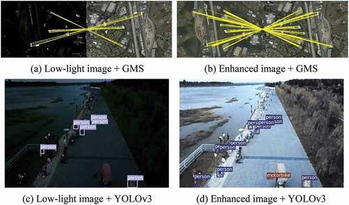
The research of visual navigation is initially inspired by the Terrain Contour Matching Guidance System in cruise missiles(Golden (Golden Citation1980)). In the following decades, there have been extensive visual navigation methods designed based on visual odometry(Comport (Comport, Malis, and Rives Citation2010); Strydom (Strydom, Thurrowgood, and Srinivasan Citation2014); Wang (Wang et al. Citation2018b); Depaola (Depaola et al. Citation2018)), simultaneous localization and mapping(SLAM) (Alpen et al. Citation2010), image matching (Xu et al. Citation2013), etc. Most visual navigation methods based on image matching use pre-stored reference images to match the image captured by the UAV with the reference image to obtain the real-time location information. However, the flying environment of the UAV is not necessarily an ideal environment with sufficient illumination. When the UAV flies on cloudy days or at night, the camera will capture low-light images due to the reduction of light, which will seriously affect the image quality, such as low contrast and low visibility. At the same time, due to the limitations of laws and regulations, manned aircraft fly much more frequently during the day than at night, which will greatly reduce the flight space of UAVs. Accordingly, the most suitable flight time for UAVs is the night with a small number of manned aircraft. Using the low-light image as the input of the high-level vision algorithm will also reduce the performance of the algorithms (e.g. image matching, object detection, etc.), as shown in . Therefore, converting low-light aerial images into high-quality normal light images can not only improve the visual quality of images but also improve the performance of UAVs in some high-level visual tasks, such as object detection (Jiang et al. Citation2021), semantic segmentation (Ke et al. Citation2020), etc, it can also enable UAV to be used in a wider range of fields, such as emergency rescue, environmental monitoring, etc.
Figure 1. Comparison of matching results and detection results between low-light image and the enhanced image obtained by our method.
Over the past few decades, there have been a large number of methods to enhance degraded images captured by insufficient illumination conditions. HE-based methods improve the global contrast by changing the histogram distribution of the weakly illuminated image into a uniform distribution, such as Brightness Preserving Dynamic HE (Ibrahim 2007) (Ibrahim and Kong Citation2007), Contrast-limiting adaptive HE (Pisano 1998) (Pisano et al. Citation1998), etc. The methods based on Retinex theory (Land Citation1977) realize image enhancement by estimating the illumination and reflectance of the image and adjusting the dynamic range of the pixels of the illumination, such as MSRCR (Jobson 1997) (Jobson, Rahman, and Woodell Citation1997), SRIE (Fu Citation2016) (Fu et al. Citation2016), etc. The learning-based methods (Shen et al. Citation2017) achieve low-light image enhancement by designing efficient models. Although these methods have made great progress in improving image contrast, most methods can not properly enhance the image contrast, the results are often over-/under-enhanced or blurred. Therefore, there is a lot of room for low-light image enhancement.
In this paper, we propose a new fully convolutional network by combining the Retinex theory with a convolutional neural network to solve the degradations of low-light images captured by UAV and improve the performance of subsequent image matching algorithms. We design a visual navigation method based on the proposed low-light image enhancement network. Extensive experiments demonstrate that the proposed image enhancement method can better improve the contrast and visual quality of low-light images. Compared with other image enhancement methods, our method can improve the performance of image matching algorithms more effectively. It can realize the positioning requirements of UAV under diverse illumination conditions.
The Proposed Low-light Image Enhancement Method
In this section, we will introduce the details of our proposed image enhancement method, including the network structure, the loss function, the dataset for training, and the implementation details.
Network Architecture
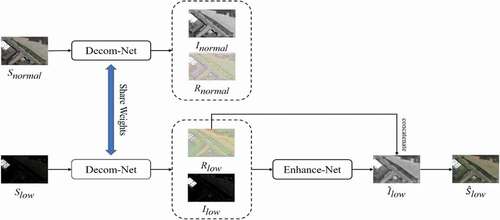
We propose a new fully convolutional network based on the Retinex theory, which consists of two subnetworks, Decomposition-Net (Decom-Net) and Enhancement-Net (Enhance-Net). The proposed low-light image enhancement pipeline is shown in . The Decom-Net decomposes the input image into an illumination and reflectance map and suppresses the noise in the reflectance at the same time. Enhance-Net takes the output of Decom-Net as the input to enhance the contrast and brightness of the illumination map. Therefore, the proposed method can improve the contrast and suppress the noise in the low-light image, and obtain the enhanced result with better visual quality.
Figure 2. The proposed low-light image enhancement pipeline. The Decom-Net decomposes the input image into an illumination map and reflectance map, and the Enhance-Net brightens up the illumination map. The reflectance map and illumination map of the low-light image are used as the input of Enhance-Net. The decompositions of normal-light images do not participate in the Enhance-Net training stage.
Decom-Net
Residual network (He Citation2016) (He et al. Citation2016) has been widely used in many computer vision tasks and achieved excellent results. Benefiting from the jump connection structure, the residual network can make the deep neural network easier to optimize during the training stage, and will not cause gradient disappearance. So, we use multiple residual components to form Decom-Net.
Decom-Net contains eight 3 × 3 convolutional layers with stride 2 and a Rectified Linear Unit(ReLU), the size of the input and output feature map of each convolutional layer are equal. By using the jump connection structure, the output result of the convolutional layer and the
convolutional layer are combined as the input of the
convolutional layer(
). The network architecture of Decom-Net is shown in .
Figure 3. The network architecture of Decom-Net.
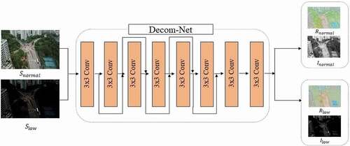
The input of Decom-Net are the low-light image and the normal-light image , and the output results are the illumination map(
/
) and the reflectance map(
/
) of the low-light image and normal-light image, respectively. But other methods based on the Retinex theory do not suppress the noise of the reflectance map in the process of decomposition. This will cause the final enhancement result to be affected by the noise in the reflectance. Benefit from the network architecture and the loss function, Decom-Net can perform decomposition and noise suppression at the same time, it can get better decomposition results.
Note that the illumination map and reflectance map of the normal-light image neither participate in the follow-up training, but only provide references for the decomposition of the low-light image. The illumination map and reflectance map of the low-light image are the input of Enhance-Net.
Enhance-Net
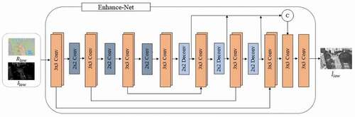
U-Net (Ronneberger Citation2015) (Ronneberger, Fischer, and Brox Citation2015) has achieved excellent results in a large number of computer vision tasks due to its excellent structural design. In the field of low-light image enhancement, a large number of networks have adopted the U-Net as the main architecture or a part of it. However, U-Net uses multiple max-pooling layers in the feature extraction stage, but the max-pooling layer will lead to the loss of a large amount of feature information. SoSpringenberg (2015) (Springenberg et al. Citation2014) replaces the max-pooling layers with stride convolutional layers, which will slightly increase the network parameters, but also improve the accuracy. Inspired by that, we use the 2 × 2 convolutional layers with stride 2 to replace the max-pooling layers in the U-Net, which is beneficial for the network to learn more feature information and maintain translation invariance. So that our network can better improve the contrast of the reflectance map.
We also utilize the multi-scale fusion, concatenate the output of each deconvolutional layer in the expansive stage to reduce the loss of feature information.
Enhance-Net contains seven convolutional blocks, each of them contains two 3 × 3 convolutional layers with stride 1 to maintain the same size of the front and the back feature maps; the first three convolutional blocks are followed by a stride convolution to perform the down-sampling; the last three convolutional blocks are followed by a deconvolutional layer to perform the up-sampling. Then, utilizing multi-scale fusion, the output of the seventh convolutional block and the output of the last three deconvolutional layers are concatenated as the input of the next convolutional layer, which can maximize the combination of context information and reduce the loss of feature information. Finally, the enhanced illumination map is obtained through a 3 × 3 convolutional layer, Each convolutional block in the Enhance-Net is followed by a ReLU. The network architecture of Enhance-Net is shown in .
Figure 4. The network architecture of Enhance-Net.
After obtaining the decomposition result of Decom-Net and the enhancement result of Enhance-Net, the output of the two subnetworks is combined by element-by-element multiplication as the final result, which can be described as:
Where is the reflectance map obtained by Decom-Net after decomposing the low-light image,
is the output of Enhance-Net, and
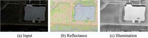
represents the element-by-element multiplication operation. The decomposition result of the whole network for a low-light image is shown in .
Figure 5. Example of the low-light image decomposition result. (a) is the input image, (b) is the reflectance map generated by Decom-Net, (c) is the illumination map generated by Enhance-Net.
Loss Function
In the training phase, Decom-Net and Enhance-Net are trained separately, so the whole loss function consists of two parts: the decomposition loss and the enhancement loss
.
Decomposition Loss
The decomposition loss consists of three components: reconstruction loss , invariable reflectance loss
, and illumination smoothness loss
:
Where and
are the coefficients to balance the consistency of the reflectance map and the smoothness of the illumination map.
Since the reflectance map and illumination map decomposed by normal-light image can be used as references for low-light image decomposition, we use the Mean Square Error (MSE) loss to represent the reconstruction loss to better realize the decomposition of the low-light image.
We also use MSE loss to form the invariable reflectance loss to constrain the decomposition process and denoise the reflectance map;
To recover the structure information, we use the weighted TV loss in (Wei et al. Citation2018) as the illumination smoothness loss;
Enhancement Loss
To make the result more realistic and natural, we also use reconstruction loss , illumination smoothness loss
, and structural similarity loss
in this stage to obtain a better result.
The illumination smoothing loss is consistent with the corresponding part of decomposition loss, and the reconstruction loss adopts the combination of MSE loss and L1 loss to obtain a better reconstruction result and further noise suppression.
The structural similarity loss adopts SSIM loss to gain better detail expression ability.
Dataset and Implementation Details
It is impractical to collect a large-scale paired low/normal-light image dataset under real conditions, all the existing aerial image datasets contain normal-light images. As far as we know, there is no paired low/normal-light aerial image dataset. Therefore, we collect 6000 high-quality aerial images in the Visdrone-2018 dataset (Zhu Citation2018) (Zhu et al. Citation2018) and follow the previous research (Lore 2017) (Lore, Akintayo, and Sarkar Citation2017) to darken the images So that we build a large-scale paired low/normal-light aerial image dataset for training. All images are resized to 600 × 400 and convert to JPG format.
At the same time, we randomly select 120 images from the dataset proposed in (Long 2017) (Long et al. Citation2017) as the test images for subsequent experiments. The image size, format, and darkening method are consistent with the training data.
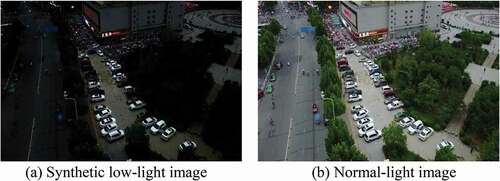
Low-Light Image Synthesis
The degradation of low-light image is mainly reflected in its low contrast. To better simulate the real weakly illuminated image, we apply Gamma Correct to each channel of the normal-light image to change the contrast. The whole process can be described as:
Where represents a normal-light image, A is a constant determined by the maximum pixel intensity in the image, and γ obeys a uniform distribution
. An example of synthetic low-light images is shown in .
Figure 6. Example of synthetic low-light image.
Implementation Details
Our implementation is done with Pytorch, the network is trained for 50 epochs on an Nvidia GTX1080Ti GPU with the proposed dataset. We use the ADAM (Kingma 2014) (Kingma and Ba Citation2014) optimizer with the parameters are =0.9,
=0.999, and
=0.0001. The batch size and patch size are set to 16 and 96, respectively. The
,
, and
0.01 in EquationEq.2
(2)
(2) and Eq.3 are all set to 0.01,
in EquationEq.5
(5)
(5) is set to 10,
and
in EquationEq.7
(7)
(7) are set to 0.5 and 1.5, respectively.
Visual Navigation System
In this section, we will introduce the visual navigation system based on the proposed low-light image enhancement method.
Image Definition Evaluation
When carrying out visual navigation tasks, UAV may be affected by factors such as insufficient lighting conditions or lack of sensor performance, so it is necessary to enhance the low-light images captured. However, not all images need to be enhanced, so it has to judge whether the image has weak illumination conditions in the pre-processing stage. In this paper, we use the Laplacian gradient function to evaluate the image definition, which is defined as follows:
Where is the convolution of the Laplacian operator at the pixel
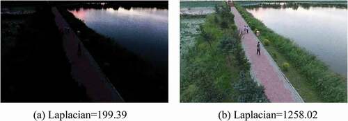
. For low-light images, the second-order partial derivative is small, so the value of the Laplacian gradient function will be small. For normal-light images, the second-order partial derivative is large, so the value of the Laplacian gradient function will be large, as shown in . Therefore, the threshold can be set by calculating the Laplacian gradient function value of each image. If it is less than the threshold we set, the image needs to be enhanced, if it is larger than the threshold, the image does not need image enhancement processing.
Figure 7. The Laplacian gradient function values of images under different illumination conditions.
Visual Navigation Pipeline
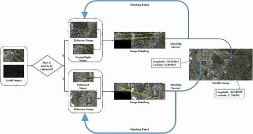
To achieve accurate positioning in the visual navigation, reference images need to be stored in advance, the geographical location information of the reference image is inputted into the database as the positioning reference. In the process of visual navigation, UAV need to judge whether the captured real-time image is under weak illumination condition firstly. If there is no lack of illumination in the image, there is no need to enhance it. If there is a lack of light in the image, the proposed image enhancement method is used to enhance it. So that the enhanced result can achieve better visual quality, and more abundant feature information can be extracted for the subsequent image matching algorithm.
The enhanced result/normal-light image and the pre-stored reference image are used as the input of the high-performance image matching algorithm. After successfully realizing the matching between the enhanced result/normal-light image and the reference image through the image matching algorithm, the location of the UAV needs to be determined. By searching the image in the reference image database with the highest matching points to the enhanced result or normal-light image is used as the current position reference image, and extract the geographical location information of the reference image as the current UAV location information. In addition, the reference images we chose are the satellite images, the reference image have a larger visual range and larger size (7200 × 3600) than the aerial images, so we split the reference image into several small-size reference images and match the aerial image with small-size images in turn, which helps to reduce the search time in the matching process. The visual navigation pipeline is shown in .
Figure 8. Visual navigation pipeline.
Experimental Evaluation
We compare the proposed method with the existing image enhancement methods through extensive experiments to verify the superiority of our method, including MF (Fu Citation2016a) (Fu et al. Citation2016a), Dong (Dong 2015) (Dong et al. Citation2015), NPE (Wang 2013) (Wang et al. Citation2013), SRIE, and Lighten-Net (Li 2018) (Li et al. Citation2018). Generally speaking, we have carried out three parts of experiments: 1) We have qualitatively and quantitatively compared the proposed method with existing methods on the synthetic test images. 2) We illustrate that our method can improve the performance of image matching algorithms. 3) We combine the proposed method with an existing image matching method to carry out the visual navigation experiment.
Low-light Image Enhancement Experiment
To verify the superiority of our method, we compare the proposed method with the existing image enhancement methods on the synthetic test images. The Peak Signal-to-Noise Ratio (PSNR) and Structural Similarity (SSIM) are used to quantitatively compare our method with other methods. For fairness, we use the public codes of these methods and do not change any of the parameters. Quantitative comparison results are shown in .
Table 1. PSNR/SSIM values on the synthetic test images. Note that the red, blue, and green in the table represent the best, sub-optimal, third-place results, respectively
Our method can not only achieve higher PSNR and SSIM than other methods, which demonstrates that our method can improve the visual quality of low-light images, but also outperform other methods in speed. The average time cost by our method to enhance per image is 0.11 seconds on the GPU faster than our competitor (Dong takes 0.61s, MF takes 1.63s, SRIE takes 58.02s, NPE takes 6.52s, and LightenNet takes 6.08s to enhance an image), which benefits from our smaller mode size (4.85MB) and better network design. The traditional methods are running on the CPU which will increase the inference time. Our results have better contrast, clearer details, and better noise suppression, as shown in .
Figure 9. Visual comparison of the synthetic test images. Please zoom in for a better view.
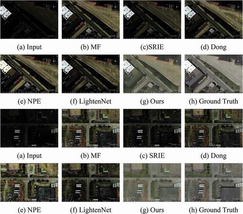
Image Matching Experiment
To verify that our method can improve the performance of the image matching algorithms, we use the proposed method and other methods to enhance the synthetic test images. Due to the lack of rotation invariant ability of the existing image matching algorithms, image rotation will seriously affect the accuracy of the algorithm, but we want to simulate the heading angle change of the UAV. Therefore, we chose to rotate the aerial image by 180° to perform our experiments. Using SIFT (Lowe Citation2004) (Lowe Citation2004), SURF (Bay Citation2006) (Bay, Tuytelaars, and Gool Citation2006), and GMS (Bian Citation2017) (Bian et al. Citation2017) algorithm to match the pre-processed images with the reference images and calculating the average number of successful matching points. Moreover, We found that when the number of extracted feature points is too small, it will cause matching failure, and when the number of extracted points is too large, it will not lead to a great improvement in accuracy but will increase the matching time. We found that when the number of extracted feature points is set to 500, there will be a better tradeoff between accuracy and speed. The image matching results are shown in .
Table 2. Comparison of matching results on the synthetic test images
After enhancing the low-light images, the average matching points have been greatly improved, and our method has achieved the best promotion effect, which proves the superiority of our method. Moreover, when our method is combined with the three methods for image matching under low-light conditions, it only takes 0.22s, 0.18s, and 0.16s to complete the matching process, respectively, which is better than other enhancement methods.
Note that the performance of the image matching algorithms will be degraded when the visual angle changes greatly. This is because the existing image matching algorithms are very sensitive to image rotation. Due to this limitation, in the following visual navigation experiment, we do not consider the pose change of the UAV, but assume that the UAV is flying flat.
Visual Navigation Experiment
In the image matching experiment, we found that GMS has the highest accuracy and the fastest speed, so we chose GMS as the matching algorithm of our visual navigation system. Moreover, when the visual angle changes greatly, it will seriously affect the accuracy of image matching algorithms (Shetty and Gao Citation2019). So we assumed that the UAV is flying flat in the visual navigation experiment, and the pose change is not taken into account.
In the visual navigation experiment, we collected a dataset which contains 5 satellite images with large visual range, and each satellite image corresponds to 10 aerial images with a small range. We take the satellite images as reference images and carry out the experiment based on the visual navigation pipeline we proposed. EquationEq.9(9)
(9) is used to darken half of the aerial images of each satellite image to simulate the low-light images, and the rest of them are used as normal light images for experiments. When the aerial images are low-light images, we use our proposed enhancement method to transform them into high-quality normal-light images and match them with the reference images.
Because the size of the satellite image we selected is too large (7200 × 3600), the matching time will be increased, so we divided the satellite image into 9 images with equal spacing, all of the small-size reference images are 2400 × 1200. During the matching process, the aerial images are matched with the small-size satellite images we obtained in turn, and the small-size images with the highest degree of matching are selected. According to the position relationship between the small-size image and the original satellite image, the aerial image is mapped to the original satellite image using homography estimation, and the longitude and latitude information of the corresponding position of the satellite image is extracted as the current position information of the UAV. Note that the geographical location of satellite images and aerial images is known.
The estimated location information we got may be different from the ground truth location information, so we use the Haversine formula to calculate the distance between the estimated position and the actual position for evaluation. The haversine formula is defined as follow:
Where (LngR, LatR) and (LngE, LatE) are location information of ground truth and our estimated results, respectively, and R is the radius of the earth. Some examples of experimental results are shown in . The red box is the region where the aerial image is mapped to the satellite image, and the red point in the yellow box is the location where the center point of the aerial image is mapped to the satellite image, and the latitude and longitude information of this red position is the current position of the UAV estimated by our method.
Figure 10. Experimental results of visual navigation.
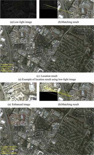

As can be seen from the experimental results, when using low-light images directly as input, the matching points are not enough to achieve self-localization, while using our method to enhance the low-light images, the image matching performance can be effectively improved and self-localization of UAV can be achieved successfully. It is proved that the visual navigation system we designed can solve the limitation of UAV visual navigation in low-light conditions and realize self-localization under diverse illumination conditions.
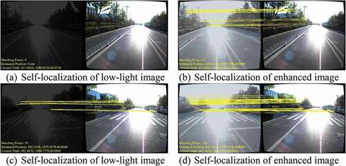
Autonomous Driving Experiment
In addition to applying our method to UAV visual matching navigation, we also want to further explore the performance of our method in other practical tasks, such as autonomous driving, etc. A large number of researchers have also tried to apply visual navigation to autonomous driving and collected many real-world datasets in different environments and different illumination conditions (e.g. 4Seasons (Wenze et al. Citation2020), Apollo Scape (Wang et al. Citation2018)).
The Apollo Scape dataset contains pairs of RGB images from different angles taken by two cameras in different streets, we use the Apollo Scape dataset for our autonomous driving experiment. We used 1121 paired images with different angles in the Apollo Scape dataset. We chose the images captured by the second camera as the reference images and use EquationEq.9(9)
(9) to darken the image captured by camera 1 to simulate the low-light image as real-time images obtained by the vehicle. By using our proposed enhancement method, the low-light images are converted into high-quality normal-light images and then matched with 1121 reference images in turn. The reference image with the highest matching degree is selected, and the position of the reference image is extracted as the current position of the vehicle. Because the images captured by the two cameras are in pairs, we considered that the self-localization failed when the enhanced results can not match the corresponding reference image correctly. At the same time, we also calculate the average matching logarithm between the enhanced image and the reference image with the highest degree of matching in the matching process, and the results are shown in .
Table 3. Self-localization accuracy and average matching points of the autonomous driving experiment
As can be seen from , our method can effectively improve the positioning accuracy of autonomous driving under low-light conditions and the accuracy of the matching algorithm. Some self-localization examples are shown in .
Figure 11. Experimental results of autonomous driving.
Conclusion
In this paper, we propose a novel low-light image enhancement method to improve the positioning accuracy of UAV visual navigation under low-light conditions. And we design a visual navigation system based on the proposed method, which can meet the navigation and positioning requirements of UAV under diverse illumination conditions. Overall, the main contributions of our work are twofold: (1): To solve the degradations in low-light images captured by UAV, we propose a new fully convolutional network, which can effectively improve the contrast of low-light images and obtain high visual quality results. (2): We design a visual navigation system based on the proposed image enhancement method. Our visual navigation system can determine the location of the UAV successfully under different lighting conditions. Moreover, we also verify that our method can effectively improve the positioning accuracy of autonomous driving based on image matching under low-light environments.
The experimental results demonstrate that the enhanced results of our method have more feature information and can meet the requirements of image matching. The visual navigation system can realize the autonomous positioning of UAV under diverse illumination conditions. In addition, there are some problems that need to be improved in the future, (1):In this paper, the low-light images we used are synthetic, but in the real-world low-light condition, the UAV will extend the camera’s exposure time to avoid the image being too dark, but this may cause the image to become blurred. Therefore, in our follow-up work, we will design an efficient network that can solve the insufficient illumination and blur in the aerial images captured under low-light conditions at the same time. (2): Although our proposed low-light enhancement method is faster than our competitors, it still can not meet the high-speed requirements (e.g. 60fps). In the future, We will explore an efficient method with excellent speed and performance to realize the real-time self-localization of UAV. (3): Because the change of the image rotation angle will seriously affect the accuracy of the image matching algorithms, we do not consider the pose change of the UAV in our experiment but assume that the UAV is flying flat. However, the pose estimation of UAV is also very important in the process of navigation, so our follow-up work will take the pose estimation into account.
Disclosure Statement
The authors declare no competing interests.
References
- Alpen, M., C. Willrodt, K. Frick, and J. Horn. 2010. On-board SLAM for indoor UAV using a laser range finder. International Society for Optics and Photonics 7692:769213.
- Bay, H., T. Tuytelaars, and L. V. Gool 2006. Surf: Speeded up robust features. 9th European Conference on Computer Vision, Graz, Austria.
- Bian, J.-W., W.-Y. Lin, Y. Matsushita, S. K. Yeung, T. D. Nguyen, and -M.-M. Cheng 2017. GMS: Grid-based motion statistics for fast, ultra-robust feature correspondence. Proceedings of the IEEE conference on computer vision and pattern recognition, Honolulu, Hawaii.
- Comport, A., E. Malis, and P. Rives. 2010. Real-time quadrifocal visual odometry. The International Journal of Robotics Research 29 (2–3):245–66. doi:https://doi.org/10.1177/0278364909356601.
- Depaola, R., C. Chimento, M. L. Anderson, K. Brink, and A. Willis 2018. UAV navigation with computer vision–flight testing a novel visual odometry technique. 2018 AIAA Guidance, Navigation, and Control Conference, Kissimmee, Florida.
- Dong, C., C. C. Loy, K.-M. He, and X.-O. Tang. 2015. Image super-resolution using deep convolutional networks. IEEE Transactions on Pattern Analysis and Machine Intelligence 38 (2):295–307. doi:https://doi.org/10.1109/TPAMI.2015.2439281.
- Dong, J.-W., and N. E. Department. 2017. Analysis on inertial navigation technology. 1st ed. Instrum Tech.China: Xian.
- Fu, X.-Y., D.-L. Zeng, Y. Huang, X.-P. Zhang, and X.-H. Ding 2016. A weighted variational model for simultaneous reflectance and illumination estimation. Proceedings of the IEEE Conference on Computer Vision and Pattern Recognition, Las Vegas, America.
- Fu, X.-Y., D.-L. Zeng, Y. Huang, Y.-H. Liao, X.-H. Ding, and J. Paisley. 2016a. A fusion-based enhancing method for weakly illuminated images. Signal Processing 129:82–96. doi:https://doi.org/10.1016/j.sigpro.2016.05.031.
- Golden, J. P. 1980. Terrain contour matching (TERCOM): A cruise missile guidance aid/Image processing for missile guidance. International Society for Optics and Photonics 238:10–18.
- He, K.-M., X.-Y. Zhang, S.-Q. Ren, and S. Jian 2016. Deep residual learning for image recognition. Proceedings of the IEEE conference on computer vision and pattern recognition, Las Vegas, America.
- Ibrahim, H., and N. S. P. Kong. 2007. Brightness preserving dynamic histogram equalization for image contrast enhancement. IEEE Transactions on Consumer Electronics 53 (4):1752–58. doi:https://doi.org/10.1109/TCE.2007.4429280.
- Jiang, Y., X. Gong, D. Liu, Y. Cheng, C. Fang, X. Shen, J. Yang, P. Zhou, and Z. Wang. 2021. Enlightengan: Deep light enhancement without paired supervision. IEEE Trans Image Process 30:2340–49. doi:https://doi.org/10.1109/TIP.2021.3051462.
- Jobson, D. J., Z. Rahman, and G. A. Woodell. 1997. A multiscale retinex for bridging the gap between color images and the human observation of scenes. IEEE Transactions on Image Processing 6 (7):965–76. doi:https://doi.org/10.1109/83.597272.
- Ke, X., W. Lin, G. Chen, Q. Chen, X. Qi, and J. Ma 2020. Edllie-net: Enhanced deep convolutional networks for low-light image enhancement. IEEE 5th International Conference on Image and Vision Computing, Beijing, China.
- Kingma, D. P., and J. Ba. 2014. Adam: A method for stochastic optimization. arXiv Preprint arXiv 1412.6980.
- Land, E. H. 1977. The retinex theory of color vision. Scientific American 237 (6):108–29. doi:https://doi.org/10.1038/scientificamerican1277-108.
- Li, C.-Y., J.-C. Guo, F. Porikli, and Y.-W. Pang. 2018. LightenNet: A convolutional neural network for weakly illuminated image enhancement. Pattern Recognition Letters 104:15–22. doi:https://doi.org/10.1016/j.patrec.2018.01.010.
- Long, Y., Y.-P. Gong, Z.-F. Xiao, and Q. Liu. 2017. Accurate object localization in remote sensing images based on convolutional neural networks. IEEE Transactions on Geoscience and Remote Sensing 55 (5):2486–98. doi:https://doi.org/10.1109/TGRS.2016.2645610.
- Lore, K. G., A. Akintayo, and S. Sarkar. 2017. LLNet: A deep autoencoder approach to natural low-light image enhancement. Pattern Recognition 61:650–62. doi:https://doi.org/10.1016/j.patcog.2016.06.008.
- Lowe, D. G. 2004. Distinctive image features from scale-invariant keypoints. International Journal of Computer Vision 60 (2):91–110. doi:https://doi.org/10.1023/B:VISI.0000029664.99615.94.
- Pisano, E. D., S.-Q. Zong, B. M. Hemminger, D. Marla, R. E. Johnston, M. Keith, M. P. Braeuning, and M. P. Stephen. 1998. Contrast limited adaptive histogram equalization image processing to improve the detection of simulated spiculations in dense mammograms. Journal of Digital Imaging 11 (4):193. doi:https://doi.org/10.1007/BF03178082.
- Ronneberger, O., P. Fischer, and T. Brox 2015. U-net: Convolutional networks for biomedical image segmentation. International Conference on Medical image computing and computer-assisted intervention, Munich, Germany.
- Shen, L., Z.-H. Yue, F. Feng, Q. Chen, S.-H. Liu, and J. Ma. 2017. MSR-net: Low-light image enhancement using deep convolutional network. arXiv Preprint arXiv 1711.02488.
- Shetty, A., and G.-X. Gao 2019. UAV Pose Estimation using Cross-view Geolocalization with Satellite Imagery. International Conference on Robotics and Automation (ICRA), Montreal, Canada.
- Springenberg, J. T., A. Dosovitskiy, T. Brox, and M. Riedmiller. 2014. Striving for simplicity: The all convolutional net. arXiv Preprint arXiv 1412.6806.
- Strydom, R., S. Thurrowgood, and M. Srinivasan 2014. Visual odometry: Autonomous uav navigation using optic flow and stereo. Proceedings of Australasian conference on robotics and automation, Melbourne, Australia.
- Wang, P., R. Yang, B. Cao, X. Wei, and Y.-Q. Lin 2018. Dels-3d: Deep localization and segmentation with a 3d semantic map. Proceedings of the IEEE Conference on Computer Vision and Pattern Recognition, Salt Lake City, Utah.
- Wang, S., R. Clark, H. Wen, and N. Trigoni. 2018b. End-to-end, sequence-to-sequence probabilistic visual odometry through deep neural networks. The International Journal of Robotics Research 37 (4–5):513–42. doi:https://doi.org/10.1177/0278364917734298.
- Wang, S.-H., J. Zheng, H.-M. Hu, and B. Li. 2013. Naturalness preserved enhancement algorithm for non-uniform illumination images. IEEE Transactions on Image Processing 22 (9):3538–48. doi:https://doi.org/10.1109/TIP.2013.2261309.
- Wei, C., W.-J. Wang, W.-H. Yang, and J.-Y. Liu 2018. Deep retinex decomposition for low-light enhancement. The British Machine Vision Conference, Newcastle, UK.
- Wenze, P., R. Wang, N. Yang, Q. Cheng, Q. Khan, L. V. Stumberg, N. Zeller, and D. Cremers 2020. 4Seasons: A cross-season dataset for multi-weather SLAM in autonomous driving. DAGM German Conference on Pattern Recognition, Tübingen, Germany.
- Xu, Z.-H., L.-X. Wu, Z. Wang, R. Wang, Z. Li, and F. Li 2013. Matching UAV images with image topology skeleton. 2013IEEE International Geoscience and Remote Sensing Symposium-IGARSS, Melbourne, Australia.
- Zhu, P.-F., L.-Y. Wen, D.-W. Du, B. Xiao, H.-B. Ling, Q.-H. Hu, -Q.-Q. Nie, C. Hao, C.-F. Liu, and X.-Y. Liu 2018. Visdrone-det2018: The vision meets drone object detection in image challenge results. Proceedings of the European Conference on Computer Vision (ECCV) Workshops, Munich, Germany.