
 ?Mathematical formulae have been encoded as MathML and are displayed in this HTML version using MathJax in order to improve their display. Uncheck the box to turn MathJax off. This feature requires Javascript. Click on a formula to zoom.
ABSTRACT
In a low-illumination environment, the contrast between lane lines and the ground is relatively low. Traditional image enhancement algorithms, such as gamma correction, Histogram Equalization, and multiple-scale Retinex, may result in over enhancement and detail loss, which decreases the detection accuracy of driver assistance systems. In this work, we introduce a low-illumination image enhancement algorithm based on improved Retinex theory and apply it to lane-line detection. A luminance channel optimization method based on a bimodal energy function is adopted to select the weight of the linear combination. A guided filter with edge-preservation is applied to obtain the illumination component of the scene. Furthermore, the reflection component is estimated in a hyperbolic tangent space, and the luminance and contrast are adaptively adjusted to obtain the enhanced image. Experimental results show that proposed method can effectively extract the lane-line edges and suppress the noise in the dark area with low lane-line illumination. Moreover, it can improve the detection success rate of an assisted driving system.
Introduction
Currently, lane-keeping support functions based on lane-line detection and lane departure warning functions in advanced driver assistance systems (ADAS) have been widely used in production vehicles. Due to insufficient light at night and severe light scattering, color shift and image detail loss often occur when preprocessing low-illumination images, which ultimately affects the accuracy of the assistance system in detecting lane lines. Intense dark areas and light sources are combined in the image. It can be seen that adaptive improvement methods are needed for these special images. To date, several illumination enhancement algorithms have been proposed, which can be roughly divided into two categories: global-based operations and non-global operations. Global operations on images mainly include logarithmic compression, gamma correction, Histogram Equalization (HE) and linear stretching. Non-global operations include Local Histogram Equalization and various filtering operations.
Because the overall luminance and contrast between the lane line and ground is insufficient, it is necessary to enhance night images with respect to contrast, brightness, and detail. Image mapping improves the quality of an image by changing the distribution between pixels via a custom function. Global-based operations use the entire image as input. Thompson et al. (Thompson, Shirley, and Ferwerda,A Citation2002) adjusted the global blue brightness in a daytime image to simulate the night environment and deliberately underexposes it to create the effect of loss of sharpness in the dim environment. Reinhard et al. (Reinhard and Devlin Citation2005) employed a computational model of photoreceptor adaptation to achieve a fast global image mapping method. The algorithm reserves four parameter interfaces for users to control contrast, overall intensity, light and chromatic adaptation. Veluchamyet al. (Veluchamy and Subramani Citation2019) combined adaptive gamma correction with Histogram Equalization to improve low-illumination images. This method can control the selection range of the histogram and reduce the occurrence of overexposure compared to the traditional HE algorithm. A global operation only selects a single function to process the image, and the run time is fast, but the processing of details is ignored. Non-global operations need to consider the current pixel and its neighboring pixels. The most common operation used on the image is convolution. Retinex-based image enhancement is a non-global method that can balance dynamic compression, edge enhancement, and color constancy. The center-surround function greatly reduces the computational cost of Retinex for image processing, which is used to enhance low-illumination images (Jobson, Rahman, and Woodell Citation1997; Rahman, Jobson, and Woodell Citation2004; Rahman and Woodell Citation1996). Due to its constant color characteristics, the enhancement of images with low-illumination can be achieved by using the Retinex algorithm for the luminance channel. Sun et al.(Sun et al. Citation2014) estimated the maximum intensity channel (MIC)based on the pixel value of the reflection points and then calculated the reflection component using bilateral filtering. Xiaoet al. (Xiao et al. Citation2016) selected the luminance channel in the color space as the input of the image by projecting the original RGB color space into the HSV color space. Based on the orthogonality of Principal Component Analysis (PCA), the image was reduced in dimension to obtain its primary information, namely, the luminance component (Mahmood et al. Citation2018; Sun, Tao, and Chen Citation2008).For image mapping, Linet al.(Lin and Shi Citation2014) used the sigmoid function to replace the logarithmic calculation in the convolution process to reduce image information loss and introduced a noise suppression factor and highlight retention factor. Kuang et al.(Kuang et al. Citation2016; Kuang, Zhang, and Li et al. Citation2016) used this method to enhance nighttime images as the training set of the detection system.
A denoised model based on fractional-order anisotropic diffusion is applied on high-pass subbands to enhance low-light images in reference (Rahman et al. Citation2021). Rahman et al. (Rahman et al. Citation2020) proposes an automatic uneven illumination image enhancement algorithm, which is capable of producing quality results for all types of images. A framework based on a camera response and weighted least-squares strategies for low illumination image is presented in reference (Rahman et al. Citation2018). The night-way images are enhancement with the equations developed using these parameters such as the light sources in the image the distance of the pixels to be calculated from the light sources, the value of the pixel itself and the neighboring pixels in Bülent’s method (Tura Citation2021). Reference (Liang, Xu, and Quan et al. Citation2020) presents a deep learning frame for low-light image enhancement with a particular focus on handling the measurement noise. A dual channel prior-based strategy for nighttime low illumination image enhancement, which builds upon bright channel prior and dark channel prior in reference (Shi, Zhu, and Guo et al. Citation2018). Zhang et al.(Zhang, Li, and Li et al. Citation2015) applies MSR algorithm to enhance image first, then use the wavelet transform algorithm to strengthen the details information to obtain a clearly image.
In a lane detection system, the detection of the lane line is generally divided into three steps: 1) The establishment of a region of interest (ROI). Previous reports (Tan, Yin, and Ouyang et al. Citation2015; Vanquang, Heungsuk, and Seochang et al. Citation2018) adopted a fixed ROI detection method, and Sonet al. (Son et al. Citation2015) selected the vanishing point as the ROI, which effectively reduces the amount of calculation. 2) Lane line edge extraction, including color information, edge, and gradient; 3) Lane line fitting. To quickly detect the lane line, Bajiwaet al.(Bajwa and Kaur, Citation2013) used the Hough transformto fit the line on a compressed JPEG image. According to (Tan, Yin, and Ouyang et al. Citation2015) and (Wang, Teoh, and Shen Citation2004), the least squaresand b-shape methods were used to fit the curve line. The selection of a polynomial fit lane line is consistent with the actual situation.For sections with straighter roads, lane lines in the ROI can be approximately treated as straight lines.
When the original Retinex algorithm is applied to process images with highlights and extreme darkness, there are several problems with the enhanced images: 1) The Retinex algorithm, respectively, estimates the reflection components of three channels, which destroys the proportional relationship among the R, G, and B channels and thus leads to image distortion.2) The brightness difference between pixels is generally ignored in Gaussian filter, resulting in the enhancement of edge blur, halo artifacts, etc., and affecting the detection of the lane line. 3) Images with low illumination can be enhanced by changing the mapping relationship between the images, and noise is also amplified during the enhancement process, especially in nighttime images.
Inspired by the properties of the hyperbolic tangent function, this function compresses the output to a range between 0 and 1. Compared with logarithmic functions, this function can expand the dark area into a larger space and compress highlights into a smaller range (less than the upper bound of the model). Therefore, no clipping is required, and no significant data loss occurs. To solve the above problem, an improved Retinex image enhancement method is proposed in this study: 1) A bimodal objective function is added to reduce the mapping sequence. The function reassigns pixels to a new range, extending the distribution of low-value pixels and other pixel values increasing smoothly.2) A guided filter with edge preservation is employed to replace theGaussian filter and to reduce the influence of halo artifacts.3) Instead of the logarithmic function, the hyperbolic tangent function is used, which can obtain a better dynamic compression range of the image. The proposed algorithm is more flexible, and it can adapt to changes of image brightness and preserve the chroma of the image. Moreover, it simultaneously guarantees real-time performance and improves the recognition rate of the lane-line detection system.
The rest of this study is arranged as follows: Section 2introducesRetinex theory, including the single-scale Retinex (SSR) algorithm and multiple-scale Retinex (MSR) algorithm; Section 3 introduces the principle of the proposed algorithm; Section 4 compares and analyzes the image quality and lane-line detection effect after enhancement, and conclusions are obtained. Section 5 summarizes the whole paper and provides a direction of future work.
Retinex Theory
Land (Land Citation1986) experimentally demonstrated that the color observed by the Human Visual System (HVS) is determined by an object’s ability to reflect long (red), medium (green), and short (blue) waves. The original image I(x,y) is further divided into an environmental illumination component L(x,y) that reflects overall changes in the image and a reflection component R(x,y) with essential image properties. The reflection component can be written as..
whererepresents the output of the Retinex algorithm in terms of R, G, and B channels; the symbol * represents the convolution operator; and F(x,y) denotes a center-surround function that typically uses a gaussian filter. The expression for F(x,y) is given by:
whereis a normalized parameter satisfying
and
is the standard deviation of the Gaussian distribution that determines the scale.
The size of the scale provides different Retinex convolution effects: a smaller value of
provides more dynamic contrast and clearer details. However, an extremely smallvalue of
can cause color distortion.In contrast, when the value
is large, more original color information of the image can be retained. However, image contrast may decrease with an increasing value of
, which affects the extraction of the feature edge of the lane line. Hence, a parameter of appropriate scale should be selected to ensure the ideal effect on the enhanced image.
In image processing, it is necessary to achieve a balance between dynamic compression and color restoration. Multi-scale Retinex is defined as the weighted sum of several SSR outputs. MSR also has multiple-scale features, and compared with the SSR algorithm, the processed image presents a better effect in local details, color fidelity and contrast. MSR can be expressed as follows:
where k is the kth parameter component under N scale parameters. In general, the ideal enhancement effect can be obtained by taking N as high, medium, and low scales.wk represents the weight associated with the kth scale parameter, and the value of wk is 1/3. Compared with SSR, image color restoration and image detail protection are greatly improved. However, the problem of halo artifacts cannot be solved completely.
Proposed Adaptive Low-illumination Image Enhancement Algorithm
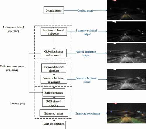
When the unmodified Retinex algorithm is used to enhance a night image, halo artifacts and over-enhancement generally occur, which seriously affects the image quality. According to the characteristic of the color constancy of Retinex, the luminance channel of the original image is selected as the input of the algorithm. First, the luminance channel of the input image is estimated by a constrained energy function, and the estimated output is then globally enhanced. Second, the illuminance component is optimized via the guided filter, and the hyperbolic tangent space is used to replace the logarithmic space to compress the images. In addition, the gain-offset operator is added to modify the reflection component adaptively. The hyperbolic tangent function infinitely compresses high-value pixels to 1, and low-value pixels are stretched to a large space. Compared with the logarithmic function, the proposed method exhibits better image dynamic compression ability, and no cropping is required, which effectively addresses the issue of over-enhancement. Finally, the enhanced luminance channel is mapped to the R, G, and B channels to obtain the color image. The framework of the proposed method is shown in .
Figure 1. Structure of the proposed model.
Luminance Channel Estimation and Global Mapping
The estimation of image illumination channels requires three channels of images to be reduced to a single channel. After graying, the estimate may affect the discrimination between different colors and cause the loss of image contrast information. A constrained energy function is introduced to protect the color contrast and information of the original image, and the linear combination optimal weight is obtained by minimizing the energy function (Lu, Xu, and Jia Citation2014; Zhao, Zhang, and Jin Citation2018). The energy function can be expressed as follows:
whereLw x andLw y refer to the luminance value and represents the color contrast, which refers to the difference between color pairs (distinguishing between positive and negative). It describes the actual distance between color pairs in the LAB color space as follows:
The original energy function pixel pairs approximately obey a Gaussian distribution where the mean is and the variance is
. As an improvement, the bimodal objective function has been added to reduce the limitations of the mapping sequence and optimize the calculation process, which can better meet the requirements of HVS. The expression for E(Lw) is given by..
where expresses the difference in output luminance of pixel points, such as x and y in pixel pool P.
The calculation process is simplified to one dimension, and the linear combination of luminance channels is expressed as follows:
where R, G andB represent a single channel of an RGB color image and refer to the weight of a linear combination. Finally, the obtained combination
is used to minimize E(Lw). It is expected that each weight is greater than 0, and the weight also needs to meet the following constraint. Their relationship is as follows:
The number of combinations of weights that satisfy these constraints is still large. Experiments show that a small change in weight has a small effect on the total output result. To reduce the amount of calculation of unnecessary weights, this paper discretizes the values of weights and increases them with a step size of 0.1 within the interval 0–1. By giving a fixed range of weights (in total), this method greatly reduces the candidate range of weights and improves operating efficiency.
After obtaining the luminance channel, tone mapping is used to expand the distribution of low-value pixels to a range more consistent with the HVS.The global luminance output can be expressed as:
where denotes the maximum value of the luminance channel
and
is the background luminance, which is obtained via the log-average of the luminance channel. It is calculated as follows:
where is the size of the image and
is a constant term that can avoid numeric overflow during the logarithm calculation. The tone mapping proposed in this paper redistributes pixels to a new range and stretches the distribution of low-value pixels, and the other pixel values increase smoothly. The algorithm ignores the preservation of details in the process of increasing brightness. After the enhancement, some high-contrast content is lost.
Local Adaptive Processing of Reflection Component
To reduce halo artifacts, various filters with edge-preservation are selected to process the input image, such as bilateral filters (Zhang et al. Citation2017) and guided filters (Ahn, Keum, and Kim et al. Citation2013; He, Sun, and Tang Citation2013). The bilateral filter algorithm has a high time complexity. An extremely large filter radius r or the original image size may affect the running speed, and the algorithm cannot meet the real-time requirements of lane-line detection. Therefore, a guided filter is selected to replace the Gaussian filter process in Retinex in this study. The guided filter uses the Euclidean distance and brightness difference as the weight reference, and it has a linear calculation process and is independent of the core size. The time complexity of the guided filter is O(N), and the processing efficiency is greatly improved compared with that of the bilateral filter.
It should be noted that the guided filter can suppress the gradient inversion effect at the edge of the image and protect its edge texture. In this section, the enhanced global brightness is taken as input, and the guided filter is selected as the center-surround function to obtain the final reflection component. The improved algorithm is as follows
where is the reflection component of the Retinex output and f() represents the guided filter function.
The guided filter creates a linear relationship between the guided image I and the filtered output image q as follows:
where is the filtering window of the guided image. The linear coefficient of
is obtained by solving the optimization problem via the least-squares method, which is given by:
where and
represent the mean and variance of the guided image in window
, respectively. The dynamic range of the output is related to the radius of the filter window r. The value ofr is 10 in this study.
represents the number of pixels in the window.
represents the average pixel value of the input image in the window.
is a regularization parameter with a range of 0 to 1, which keeps the value of
within the range.The higher the value of
, the clearer the edge of the image.
To simplify the calculation process, the global adaptive output is selected as the guide image and the input image. The equation is as follows:
The guided filter successfully reduces the effect of halo artifacts, and it also has a protective effect on larger pixels, leading to a smaller difference between the output filtered image and the input image.
Based on the activation function in a neural network, the hyperbolic tangent function can also compress the dynamic range. The mapping range of pixel values is changed to suppress the over-enhancement of the image. In this study, a gain-offset factor is added to EquationEquation (11)(11)
(11) to modify the output image. The hyperbolic tangent space is used to map the reflection component rather than the logarithmic space. The improved Retinex algorithm is given by..
where Ga refers to a correction factor based on the global luminance output. It adjusts the overall contrast of the reflected component and suppresses excessive enhancement of the low-illumination region. It can be written as:
where is the maximum value of global adaptive luminance.
is the regulating constant and adjusts the weight of
and
. The value of
is 25 in this study.
The correction factor offset for the ratio of global adaptive output and guided filter output Occan be expressed as:
where is the log-average of the global adaptive output of the luminance channel.
is the adjustment coefficient of
. Its value is 4 in this study.The basic algorithm steps are described in .
Table 1. Steps of the proposed algorithm
Experimental Results and Discussion
To verify the effectiveness of the proposed algorithm for image enhancement, low-illumination lane line images of different scenes in the Tusimple dataset and CUlanedataset(Pan, Shi, and Luo et al. Citation2018) were randomly selected as the experimental data. The Tusimple database consists of 7498 video segments including road driving images at different periods during the day with size of 1280 × 720. The CUlane database was captured from six cameras mounted on six vehicles driven by different drivers by the Hong Kong University. There are 133,235 samples in CUlane database including 88,880 in the training set, 9,675 in the verification set, and 34,680 in the test set. The resolution and gray scale of captured finger images was 1640 × 590.
The enhancement effect of the proposed algorithm on low-illumination images is compared with that of the MSR(Xiao et al. Citation2016), MSRCR(Rahman, Jobson, and Woodell Citation2004), LB-MSR(Tao and Asari Citation2003), and Durand(Durand and Dorsey Citation2002) algorithms, particularly in terms of image quality and time cost. The experimental parameters are consistent with the original articles.
Image Quality Evaluation
In this section, low-illumination nighttime images and daytime images are selected as references to verify the effectiveness of the proposed algorithm for day and night environments. and display the enhancement outputs of MSR, MSRCR, LB-MSR, Durand’s algorithm, SSR, Guided Filter and the proposed method.
Figure 2. Original images and results from different algorithms on CUlane: (a) the original image, (b) MSR, (c) MSRCR, (d) LB-MSR, (e) Durand’s algorithm(f) SSR, (g) guided filter and (h) proposed method.
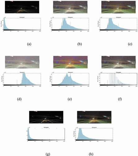
Figure 3. Original images and results from different algorithms on Tusimple: (a) the original image, (b) MSR, (c) MSRCR, (d) LB-MSR, (e) Durand’s algorithm, (f) SSR, (g) guided filter and (h) proposed method.
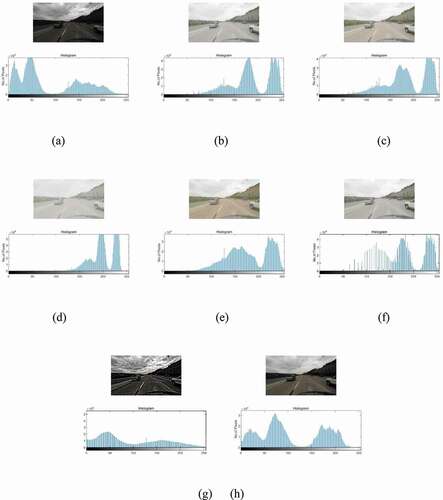
According to the histogram analysis, the histogram of the image enhanced by MSR, MSRCR, LB-MSR, SSR, Guided Filter, and Durand’s algorithm shows irregular peaks and outliers. This result shows that the algorithm is not efficient in noise control, and the nighttime image needs further improvement. Compared with other algorithms, the image information enhanced by SSR, MSR and LB-MSR is concentrated on the right side of the histogram. In addition, the overall image is white and bright, especially the daytime low-illumination image, which is not suitable for image enhancement in well-lit conditions. The output images obtained by Durand’s algorithm and Guided Filter have high saturation, and enhancement operations in low-light scenes can easily cause image distortion. In the MSRCR method, a color restoration factor is added to adjust color distortion based on the MSR method. Moreover, there is no significant change in the histogram distribution compared with MSR. The proposed algorithm can enhance the image in both night and day conditions. The resulting histogram is uniformly distributed, with fewer overexposed areas, and the proposed algorithm is superior to other algorithms in image detail processing.The color restoration and edge protection of the resulting image are particularly enhanced compared with other algorithms. The proposed algorithm effectively reduces the effect of halo artifacts and protects the image from over-enhancement.
To further verify the authenticity of these conclusions, this study investigates the advantages of the proposed algorithm with the peak signal-to-noise ratio (PSNR), image entropy, and real-time performance.
The PSNR is a widely used objective evaluation index of images. As shown , the PSNR values of the proposed algorithm in and ) are close to those of the other four algorithms. Nevertheless, the enhancement effect of the remaining images from the proposed algorithm is remarkable. shows a daytime image with low illumination. ) shows a tunnel. However, there is enough light on the left to improve the overall brightness of the image. Based on the analysis of the images, the PSNR of low-illumination daytime images is considerably different from the actual subjective evaluation. This difference can be explained by the PSNR being based on the error between corresponding pixels without considering the visual characteristics of the HVS. As a result, the evaluation results may be inconsistent with subjective human perception.
Table 2. The PSNR comparison of the image enhancement algorithms
Figure 4. Lane line detection results with various illumination conditions: (a) inside a tunnel, (b) an urban arterial road, (c) highways supplemented by a larger number of light sources, (d) highways supplemented by a smaller number of light sources and (e) a single-lane highway without additional light sources.
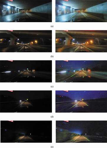
Image entropy refers to the amount of information in an image. shows the entropy of seven images. The contrast of the low-illumination image is poor, resulting in a low entropy value. The proposed method shows certain improvements compared with MSR and LB_MSR, and it has a similar value to MSRCR and Durand. The algorithm presented in this paper effectively maintains the contrast of the output image, and the enhanced image looks more natural.
Table 3. The entropy comparison of different image enhancement algorithms
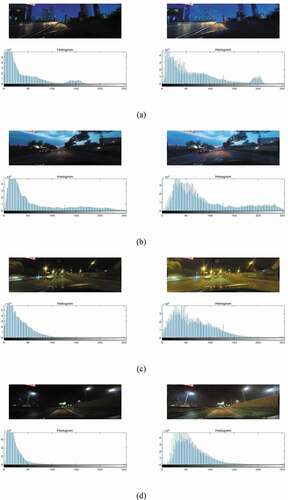
In , the visual results produced by the proposed model on different complex low-illumination images to validate the performance of our method. ) displays the urban road without additional street lamp light sources at about dusk, the urban road supplemented by a smaller number of light sources at dusk, an urban road supplemented by a larger number of light sources and highways supplemented by a smaller number of light sources at night time. The experimental results show that proposed algorithm has good enhancement effect on images with different complex low-illumination conditions. The histograms of resulting images are uniformly distributed with fewer overexposed areas. The proposed algorithm effectively reduces the effect of halo artifacts and protects the image from over-enhancement.
Figure 5. Enhancement results with complex low-illumination conditions: (a) urban road without additionalstreet lamp light sources at about dusk, (b) urban road supplemented by a smallernumber of light sources at dusk, (c) urban road supplemented by a larger number of light sourcesat night time, and (d) highways supplemented by a smallernumber of light sourcesat night time.
Time Cost
shows the processing time of seven images processed by different algorithms. The LB_MSR and Durand methods are based on the single-channel Retinex enhancement algorithm, which sacrifices image quality to obtain a short image processing time. The proposed method in this study has advantages in runtime compared with other three-channel-based enhancement algorithms, which can basically satisfy the need of real-time requirements of urban road driving.
Table 4. Comparison of the processing time of the image enhancement algorithms(s)
Lane Line Detection Results with Various Illumination Conditions
After preprocessing a low-illumination lane-line image, the lane line can be detected. First, a Canny operator is used to detect the lane line. The second step is to manually select the vehicle driving area (Wu, Chang, and Lin Citation2014). The third step is to use sliding windows to detect lane-line information and fit a polynomial. As shown in , the five original images on the left are divided into five levels according to the light condition. ) displays a lane line image with a sufficient single-sided light source in the tunnel. ) shows a lane line image in an urban arterial road, with the main light sources coming from lights on both sides of the street. ) shows a light source that mainly comes from the vehicle itself on the highway, and it is supplemented by light from vehicles traveling in the opposite or same direction. ) presents a scene similar to that of ). The light source comes from the vehicle itself and vehicles from the opposite direction, and some lane lines on the right side of the vehicle are missing. ) shows a situation where the only light source is from the vehicle, on a single-lane highway, and where the visible area is limited. The right side of demonstrates the detection result of the lane line after enhancing the low illumination.
It should be noted that this study focuses on the enhancement of low-illumination images, and the selection of the ROI is based on the camera position. Generally, according to the principle of projection, the middle area of the image is chosen as the upper boundary of the ROI. The location of the camera determines the lower boundary of the ROI. As shown in ) and ), the hood of the vehicle blocks less road information, and thus, the cropped redundant area is set to one-sixth of the image. In ), the hood of the vehicle is more obstructed, and the cropped redundant area is set to one-third of the image. Based on the detection results, the low-illumination image enhancement algorithm can improve the overall brightness of the image, protect its contrast and suppress noise. The lane-line detection system can identify lane-line information in low-illumination environments.
Conclusion and Future Work
With the advanced development of autonomous driving technology, an autonomous system can realize detection functions in various scenarios. This study proposes a low-illumination lane image enhancement technology for lane-line detection based on Retinex that processes the luminance channel based on both global and local aspects. In the global process, luminance estimation based on the energy function can maintain the contrast of the original image. In local processing, a gain-offset operator is introduced to adaptively adjust the output of the Retinex algorithm, which prevents the structure of the guided filter output image from being similar to that of the luminance image. The hyperbolic tangent function is used to change the mapping interval and expand the pixel distribution in the dark parts of the image, avoiding the loss of image information and over-enhancement in dark situations.
The above methods can compress the dynamic range of low illuminance, enhance image brightness, protect the detail of images and obtain lane-line enhancement images with high contrast. The algorithm proposed in this study is suitable for the lane-line detection of low-illumination images in day and night. In the future, this enhanced algorithm will be combined with a state-of-the-art lane-line detection algorithm, which should achieve remarkable detection results. Furthermore, it is seen from that the application of the proposed method takes approximately 0.5 s. This means that the algorithm must be accelerated in terms of time in order to be used in real-time applications on future.
Acknowledgments
This work is partially supported by the Specialized Fund for the Basic Research Operating Expense Program of Heilongjiang Province (RCYJTD −201806).
Disclosure Statement
No potential conflict of interest was reported by the author(s).
Additional information
Funding
References
- Ahn, H., B. Keum, D. Kim, and H. S. Lee. Adaptive local tone mapping based on Retinex for high dynamic range images, 2013 IEEE International Conference on Consumer Electronics (ICCE), IEEE, Las Vegas, NV, USA, 153–56.
- Bajwa, A., and R. Kaur. 2013. Fast lanedetection using improved houghtransform. Journal of Computing Technologies 2 (5):10–13.
- Durand, F., and J. Dorsey. 2002. Fast bilateral filtering for the display of high-dynamic-range images. ACM Transactions on Graphics (TOG), ACM 21 (3):257–66. doi:https://doi.org/10.1145/566654.566574.
- He, K., J. Sun, and X. Tang. 2013. Guided image filtering. IEEE Transactions on Pattern Analysis and Machine Intelligence 35 (6):1397–409. doi:https://doi.org/10.1109/TPAMI.2012.213.
- Jobson, J., Z. Rahman, and A. Woodell. 1997. Properties and performance of a center/surround Retinex. IEEE Transactions on Image Processing A Publication of the IEEE Signal Processing Society 6 (3):451–62. doi:https://doi.org/10.1109/83.557356.
- Kuang, H., L. Chen, F. Gu, J. Chen, L. Chan, and H. Yan. 2016. Combining region of interest extraction and image enhancement for nighttime vehicle detection. IEEE Intelligent Systems 31(3):57–65. doi:https://doi.org/10.1109/MIS.2016.17.
- Kuang, H., X. Zhang, J. Li, L. Chan, and H. Yan. 2016. Nighttime vehicle detection based on bio-inspired image enhancement and weighted score-level feature fusion. IEEE Transactions on Intelligent Transportation Systems 18 (99):1–10.
- Land, E. 1986. An alternative technique for the computation of the designator in the Retinex theory of color vision. Proceedings of the National Academy of Sciences 83 (10):3078–80. doi:https://doi.org/10.1073/pnas.83.10.3078.
- Liang, J., Y. Xu, Y. Quan, and J. Wang. Deep bilateral Retinex for low-light image enhancement,(2020)1–15.
- Lin, H., and Z. Shi. 2014. Multi-scale Retinex improvement for nighttime image enhancement,Optik. International Journal for Light and Electron Optics 125 (24):7143–48. doi:https://doi.org/10.1016/j.ijleo.2014.07.118.
- Lu, C., L. Xu, and J. Jia. 2014. Contrast preserving decolorization with perception-based quality metrics. International Journal of Computer Vision 110 (2):222–39. doi:https://doi.org/10.1007/s11263-014-0732-6.
- Mahmood, Z., N. Muhammad, N. Bibi, Y. M. Malik, N. Ahmed. 2018. Human visual enhancement using multi-scale Retinex. Informatics in Medicine Unlocked 13:9–20. doi:https://doi.org/10.1016/j.imu.2018.09.001.
- Pan, X., J. Shi, P. Luo, X. Wang, and X. Tang. Spatial as deep: Spatial CNN for traffic scene understanding, Thirty-Second AAAI Conference on Artificial Intelligence, Louisiana, USA, 2018.
- Rahman, Z., and A. Woodell, Multi-scale Retinex for color image enhancement, International Conference on Image Processing, IEEE, Lausanne, Switzerland, 3(1996)1003–06.
- Rahman, Z., J. Jobson, and A. Woodell. 2004. Retinex processing for automatic image enhancement, human vision and electronic imaging VII. International Society for Optics and Photonics 13 (1):100–11.
- Rahman, Z., M. Aamir, Y. F. Pu, F. Ullah. 2018. A smart system for low-light image enhancement with color constancy and detail manipulation in complex light environments. Symmetry 10(12):718. doi:https://doi.org/10.3390/sym10120718.
- Rahman, Z., Y. F. Pu, M. Aamir, S. Wali. 2021. Structure revealing of low-light images using wavelet transform based on fractional-order denoising and multiscale decomposition. The Visual Computer 37(5):865–80. doi:https://doi.org/10.1007/s00371-020-01838-0.
- Rahman, Z., Y. F. Pu, M. Aamir, S. Wali, and Y. Guan. 2020. Efficient image enhancement model for correcting uneven illumination images. IEEE Access 8:109038–53. doi:https://doi.org/10.1109/ACCESS.2020.3001206.
- Reinhard, E., and K. Devlin. 2005. Dynamic range reduction inspired by photoreceptor physiology. IEEE Transactions on Visualization and Computer Graphics 11 (1):13–24. doi:https://doi.org/10.1109/TVCG.2005.9.
- Shi, Z., M. Zhu, B. Guo, M. Zhao, and C. Zhang. 2018. Nighttime low illumination image enhancement with single image using bright/dark channel prior. EURASIP Journal on Image and Video Processing 13:1–15.
- Son, J., H. Yoo, S. Kim, K. Sohn. 2015. Real-time illumination invariant lane detection for lane departure warning system. Expert Systems with Applications 42(4):1816–24. doi:https://doi.org/10.1016/j.eswa.2014.10.024.
- Sun, B., W. Tao, and W. Chen. 2008. Luminance based MSR for color image enhancement. International Congress on Image and Signal Processing 3:358–62.
- Sun, W., L. Han, B. Guo, W. Jia, M. Sun. 2014. A fast color image enhancement algorithm based on max intensity channel. Journal of Modern Optics 61(6):466–77. doi:https://doi.org/10.1080/09500340.2014.897387.
- Tan, T., S. Yin, and P. Ouyang. Efficient lane detection system based on monocular camera, 2015 IEEE International Conference on Consumer Electronics (ICCE), IEEE, Las Vegas, Nevada, USA, (2015) 202–03.
- Tao, L., and V. Asari, Modified luminance based MSR for fast and efficient image enhancement, 32nd Applied Imagery Pattern Recognition Workshop, IEEE, Washington, DC,USA, (2003) 174–79.
- Thompson, W., P. Shirley, and J. Ferwerda,A. 2002. spatial post-processing algorithm for images of night scenes. Journal of Graphics Tools 7 (1):1–12. doi:https://doi.org/10.1080/10867651.2002.10487550.
- Tura, B. 2021. An image enhancement method for night-way images. Journal of Electrical &computer Engineering 9 (1):8–16.
- Vanquang, N., K. Heungsuk, J. Seochang, and B. Kwangsuck. 2018. A study on real-time detection method of lane and vehicle for lane change assistant system using vision system on highway. Engineering Science and Technology 21 (5):822–33.
- Veluchamy, M., and B. Subramani, Image contrast and color enhancement using adaptive gamma correction and histogram equalization,Optik, 183 (2019) 329–37.
- Wang, Y., E. Teoh, and D. Shen. 2004. Lane detection and tracking using B-Snake. Image and Vision Computing 22 (4):269–80. doi:https://doi.org/10.1016/j.imavis.2003.10.003.
- Wu, P., C. Chang, and C. Lin. 2014. Lane-mark extraction for automobiles under complex conditions. Pattern Recognition 47 (8):2756–67. doi:https://doi.org/10.1016/j.patcog.2014.02.004.
- Xiao, J., H. Peng, Y. Zhang, C. Tu, and Q. Li. 2016. Fast image enhancement based on color space fusion. Color Research and Application 41(1):22–31. doi:https://doi.org/10.1002/col.21931.
- Zhang, S., T. Wang, J. Dong, and H. Yu. 2017. Underwater image enhancement via extended multi-scale Retinex. Neurocomputing 245:1–9. doi:https://doi.org/10.1016/j.neucom.2017.03.029.
- Zhang, W., H. Li, and H. Li. A novel method for low illumination image,8th International Symposium on Computational Intelligence and Design, Hangzhou, China, (2015)1–5.
- Zhao, H., H. Zhang, and X. Jin. 2018. Efficient image decolorization with a multimodal contrast-preserving measure. Computers & Graphics 70:251–60. doi:https://doi.org/10.1016/j.cag.2017.07.009.