Abstract
The manufacture and preliminary testing of a drag-reducing riblet texture with fouling-control properties is presented. The commercial fouling-release product Intersleek® 1100SR was modified to manufacture riblet-textured coatings with an embossing technology. Hydrodynamic drag measurements in a Taylor–Couette set-up showed that the modified Intersleek® riblets reduced drag by up to 6% compared to a smooth surface. Barnacle settlement assays demonstrated that the riblets did not substantially reduce the ability of Intersleek® 1100SR to prevent fouling by cyprids of Balanus amphitrite. Diatom adhesion tests revealed significantly higher diatom attachment on the riblet surface compared to smooth Intersleek® 1100SR. However, after exposure to flow, the final cell density was similar to the smooth surface. Statically immersed panels in natural seawater showed an increase of biofilm cover due to the riblets. However, the release of semi-natural biofilms grown in a multi-species biofilm culturing reactor was largely unaffected by the presence of a riblet texture.
Introduction
The problem of biofouling accumulation on the surfaces of artificial structures is well documented (Woods Hole Oceanographic Institution Citation1952). Fouling has problematic consequences in the context of marine transport; the increased hull roughness associated with marine growth results in a significant increase in hydrodynamic drag and a reduction in vessel performance. Severe fouling can increase fuel consumption by 40% at cruising speed and can escalate overall voyage costs by 77% (Schultz Citation2007).
The scale of the problem is clear from the size of the global trading fleet that consisted of 58,000 vessels at the end of 2016 (Department for Transport Citation2017), and the significant fuel consumption of a single vessel, eg 100 t of bunker fuel per day for a very large crude carrier. Metrics for the period 2007–2012 suggest that the average annual fuel consumption for all shipping ranged between ~247 million and 325 million tonnes (Mt) of fuel with the associated average annual emission of carbon dioxide between 739 and 1135 Mt (Smith et al. Citation2015). The benefits of minimising hull roughness through the application and use of effective hull fouling control solutions are therefore obvious, namely reduced costs and emissions. Over recent years, these benefits have been the principal motivating factors for the development of technologically sophisticated biocidal antifouling (AF) and non-biocidal fouling-release (FR) coatings (Yebra et al. Citation2004; Finnie and Williams Citation2010; Lejars et al. Citation2012). Such coatings help to preserve the smooth surface of the vessel hull, thereby minimising hydrodynamic drag.
A next significant challenge to researchers in this field is to design and formulate coating systems that maintain the desired fouling-control performance whilst additionally offering hydrodynamic benefits beyond those which are achievable from a smooth surface. For instance, the hydrodynamic drag in a turbulent flow can be reduced with the use of a riblet texture. This texture has been found on the scales of some shark skins and consists of ridges or riblets aligned with the mean flow direction (Dean and Bhushan Citation2010). A drag reduction of 8.2% has been obtained with a simplified geometry of trapezoidal grooves with wedge-like ribs (Bechert et al. Citation1997). Researchers from Fraunhofer IFAM developed a simultaneous embossing-curing technology to produce riblet-textured paints denoted as Dual-cure Riblets; maximum drag reductions of 5.2% and 6.2% have been measured in water and air, respectively (Stenzel et al. Citation2011).
The utility of these riblet paints in under-water applications is however compromised by the absence of fouling-control properties. Investigations showed that micro-textured surfaces, including similar riblet designs, may reduce colonisation by certain biofouling organisms, such as barnacle cyprids (Berntsson et al. Citation2000; Ring Citation2000). However, many other fouling taxa are not deterred by surface topographies in the micrometre range. Organisms settling on the riblet-textured surface will have a detrimental effect on its drag-reducing performance; hence the need for fouling-controlling riblet textures. Addition of biocides to the non-eroding dual-cure paint formulation only provided limited protection against biofouling. After 12 months of static immersion the tested surfaces were overgrown with macrofouling since the biocide concentration in the near-surface coating layers was too low to maintain the AF effect (Stenzel et al. Citation2016).
One solution would be to produce a riblet coating using a material or surface that is already known to have good AF or FR properties. This work describes the design, synthesis and preliminary testing of a single synthetically engineered solution which effectively combines the fouling-control properties of the commercial FR product Intersleek® 1100SR with the drag-reducing properties of the riblet texture.
Methods
Coating description and manufacturing
An overview of the different coatings with their name, short description and application method is presented in Table . A more extensive description is given below, as well as details of the process for manufacturing the riblet surfaces.
Table 1. Name, description and application method for the different coatings.
Dual-cure Riblets
The general principle of the (automated) embossing-curing technology for painted Dual-cure Riblets is described by Stenzel et al. (Citation2011) and Kordy (Citation2015) and illustrated in Figure . The paint formulation is based on a combination of two separate curing mechanisms; to fix the microstructure, UV-curable acrylate binders were used, and to achieve good wear resistance polyurethane components were integrated for a post-curing step.
Figure 1. Schematic of the simultaneous embossing-curing technology developed by Fraunhofer IFAM (see also Kordy Citation2015).
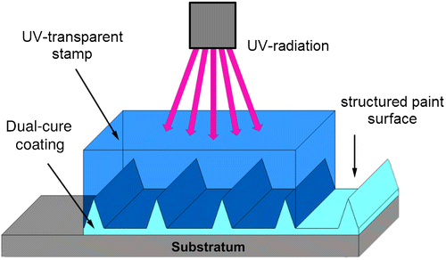
The riblet-textured coating surfaces in the present work were produced manually. A transparent silicone film carrying the negative of the micro-structure was used as an embossing tool. The dual-cure coating was applied to the silicone mould which was placed on the substratum. A self-adhesive PVC foil (Ritrama L-100) was used as the substratum in order to facilitate application to the Taylor–Couette cylinders (used for hydrodynamic testing, see the next subsection). For curing, the samples were moved at slow speed (1.5 m min−1) under a mercury vapour lamp which delivered 80 W cm−1 over the lamp length. Removal of the embossing tool then reveals the desired well-resolved structure transferred to the coating (Figure ).
Figure 2. SEM images of the two different riblet-textured coating systems: Dual-cure Riblets (a) and Modified Intersleek® Riblets (b). The inset defines three riblet characteristics, namely spacing, height and tip angle.
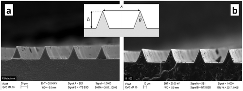
Texture characteristics were measured by scanning electron microscopy (SEM, Zeiss EVO MA 10, 20 kV acceleration voltage, type I secondary electrons, 6.0/5.5 mm working distance, Carl Zeiss AG, Jena, Germany). Cryo-fractures using liquid nitrogen were made and the samples were sputtered with gold for 1 min at 25 mA. Figure a shows a SEM image of the Dual-cure Riblet texture. The riblet characteristics, defined in Figure and measured by SEM, are spacing s = 91.7 ± 1.3 μm, height 42.4 ± 0.5 μm and tip angle θ = 41.5 ± 0.9°. The mechanical coating properties were measured by a tensile test, and are specified with an elastic modulus of 125 MPa and a tensile strength of 8.5 MPa.
Intersleek® 1100SR
Intersleek® 1100SR is an advanced fluoropolymer FR coating that is free of biocides. It is primarily intended for commercial marine vessels and is designed to release marine biofilms even at low speeds. The technology provides a smooth, low-energy surface to which fouling organisms either cannot attach, or to which they adhere only loosely and can therefore easily be removed. In order to ensure maximum smoothness of the surface, it is important to strictly adhere to the application guidelines. For instance, the preferred method of application is airless spray, which is by far the most common method used in marine shipyards for application of paint to large areas.
Modified Intersleek®
To produce coated foils with a riblet structure, the application scheme of Intersleek® 1100SR was modified for three reasons, namely (1) to use self-adhesive PVC foil as the substratum, (2) to apply the coated foil to the curved surface of the Taylor–Couette cylinders (used for hydrodynamic testing, see the next subsection), and (3) to convert the Intersleek® 1100SR finish from one optimised for airless spray application to one compatible with the riblet manufacturing process. The first two points were addressed by replacing the standard primer (Intershield® 300) with Intersleek® 7180; this had superior adhesion to PVC and it was sufficiently flexible to allow the coated film to be bent to a radius of 11.0 cm (matching the Taylor–Couette cylinders) without cracking. The third point required the modification of the Intersleek® 1100SR coating system, as described below.
Initial attempts to prepare riblet surfaces from Intersleek® 1100SR produced articles with poor fidelity. Specifically, the texture was poorly reproduced due to shrinkage on cure. In addition, the riblet-textured coating exhibited surface defects, which resulted from evaporating solvent and poor mould release. These issues were mainly attributed to the solvent content of the Intersleek® 1100SR formulation. Specifically, Intersleek® 1100SR is a three component formulation with mix ratios of nine volumes Part A to two volumes Part B to one volume Part C, and an overall volume solids of 72% ± 2% (ISO 3233:1998). Without the requirement for adequate sprayability, flow and levelling, a modified formulation was prepared where all the non-essential solvent was removed. Parts A and B were converted into 100% volume solid components. Part C was used without modification. With a new mix ratio of 10 volumes Part A to 0.4 volumes Part B to one volume Part C, the total volume solids of the mixed components was calculated as being 96%. This coating formulation is denoted as Modified Intersleek®. Its mechanical properties were measured with a tensile tester, and are specified with an elastic modulus of 0.87 MPa and a tensile strength of 0.84 MPa.
Modified Intersleek® Riblets
The Modified Intersleek® formulation was used to manufacture riblet-textured coatings. Embossing was performed with the same silicone moulds as for the Dual-cure Riblets. Prior to use for the Modified Intersleek®, the silicone moulds were subjected to a low-pressure plasma treatment which generates a thin (nm scale) organosilicon film (ReleasePLAS®) at the mould surface in order to achieve complete de-moulding of the Intersleek® coating. The coatings were conventionally cured at room temperature for 24 h before the mould was removed. The resulting textured coating is denoted as Modified Intersleek® Riblets. The quality of the riblet structure was investigated by scanning electron microscopy. Figure b shows a SEM image of the resulting texture. The riblet characteristics, defined in Figure and measured by SEM, are spacing s = 92.7 ± 0.7 μm, height 42.4 ± 0.5 μm and tip angle θ = 41.7 ± 1.2°.
In addition to the foils for hydrodynamic testing, riblet surfaces were coated on to the surfaces of standard glass microscope slides (76 × 26 mm) for laboratory fouling assays. Slides were produced with two riblet orientations: Flow Aligned (FA), with riblets running parallel to the long axis of the glass slide, such that they were aligned with the flow of water in biofouling removal tests (see below); and Flow Normal (FN), with riblets running parallel to the short axis of the glass slide, such that they were normal to the flow in biofouling removal tests.
Hydrodynamic drag measurements
Hydrodynamic drag of coated cylinders was measured with a Taylor–Couette facility at the TU Delft (Figure ). It consists of two concentric cylinders of acrylic glass (Plexiglas, PMMA): an inner cylinder and an uncoated outer cylinder. The curved outer surface of the inner cylinder was either coated or uncoated; the top and bottom end plates were uncoated. The height of the cylinders was 21.7 cm for the inner cylinder and 22.0 cm for the outer cylinder. Small gaps (Von Kármán gaps) of about 1.5 mm were present between the bottom and top end plates of the two cylinders. The radius of the inner surface of the outer cylinder was 12.0 cm. The radius of the outer surface of the inner cylinder varied between 11.00 cm and 11.09 cm, depending on the radius of the uncoated cylinder and the thickness of the applied coating. The radial gap in between the cylinders (Taylor–Couette gap) had thus a width between 0.91 and 1.0 cm. The Taylor–Couette gap and both Von Kármán gaps were filled with demineralised water.
Figure 3. Taylor–Couette set-up at the TU Delft. (a) A cylinder with Dual-cure Riblets; (b) a cylinder with Modified Intersleek® Riblets; (c) a mounted inner cylinder with an uncoated surface. The outer cylinder (not shown here) is mounted on the brass bottom plate. (d) The fully mounted set-up before it is filled with water. The brass bottom and top plates of the outer cylinder are visible.
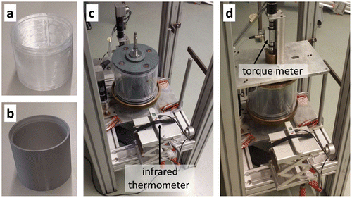
The drag of the inner cylinder was determined from the torque on the inner cylinder measured with a co-rotating torque meter in the shaft. An infrared thermometer was used to determine the instantaneous temperature of the outer cylinder wall, which was then used to infer the instantaneous water temperature and viscosity. In a typical experiment of approximately 78 min, the fluid temperature rose 4–5°C. Before a coated cylinder was measured, it was soaked in demineralised water for at least two weeks to reduce the possibility that coating compounds (eg residual solvent) would contaminate the demineralised water in the Taylor–Couette set-up. Care was taken to remove air bubbles that could be present in the set-up. Measurements were performed at exact counter-rotation: the cylinders rotate in opposite directions with exactly the same surface speed. The cylinder speed was increased in 38 steps from 0 to about 4.6 m s−1, such that the velocity difference (or shear velocity Ush) between the surfaces of the two cylinders varied from 0 to 9.2 m s−1. At each cylinder speed, torque measurements were taken at a sampling frequency of 2 kHz for 120 s. The average torque was determined from the last 100 s to ensure that the cylinders were moving at constant speed.
The measurement data were processed to obtain the drag coefficient Cd as function of the shear Reynolds number Res. They are defined as follows:
with τw the drag force per unit area (or wall shear stress) on the curved surface of the inner cylinder (computed from the measured torque), ρ the fluid density, Ush the velocity difference between both cylinders (also called the shear velocity), d the radial gap width (cylinder and coating dependent, between 0.91 and 1.0 cm) and ν the kinematic fluid viscosity (temperature dependent, approximately 10−6 m2 s−1 at 20°C). The following relation between Res and Ush can be used as a rule of thumb: Res ≈ 104 ⋅ Ush.
To quantify the influence of the riblet coatings on the drag, the drag change DC is introduced. Let represent the drag coefficient of a smooth (ie uncoated) cylinder, then DC is defined as:
It represents the change in drag as compared to the reference drag of a smooth cylinder. Drag increase corresponds with a positive DC, while drag is reduced when DC is negative. Both Cd and DC were computed from the measured torque following the methods described by Greidanus et al. (Citation2015).
Barnacle settlement assay
Adult barnacles, Balanus amphitrite (=Amphibalanus amphitrite), were cultured, induced to release nauplii and reared to the cyprid stage following the methods outlined in Hellio, Marechal et al. (Citation2004), and Hellio, Simon-Colin et al. (Citation2004), except that all stages were carried out in 32 psu artificial seawater (ASW; Tropic Marin, Wartenberg, Germany), and nauplii were reared on Tetraselmis suecica.
Barnacle settlement testing was carried out on coated glass microscope slides: three slides of Intersleek® 1100SR, seven slides of Modified Intersleek® Smooth and seven slides of Modified Intersleek® Riblets, along with six slides coated with polydimethylsiloxane (PDMS; Dow Corning 3-0213, Dow Corning Corporation, Auburn MI, USA). All replicate slides were placed in quadriPERM dishes (Sarstedt, Nümbrecht, Germany) and a 500 μl droplet of 0.22 μm-filtered ASW was pipetted onto each slide surface. Twenty (± 2) cypris larvae were added to the droplet in a minimal volume of ASW using a glass Pasteur pipette. Samples were then incubated at 28°C in conditions of high humidity, in the dark. The numbers of settled cyprids on each replicate were counted after 48 h.
Diatom adhesion and ease-of-removal assay
Six slides each of Modified Intersleek® Smooth, Modified Intersleek® Riblets FA, Modified Intersleek® Riblets FN, PDMS, uncoated glass, and four slides of standard Intersleek® 1100SR, were wetted in deionised water for 24 h and then transferred to 30 psu ASW for a further 24 h prior to testing. Cells of the diatom Navicula incerta were cultured in F/2 medium in 250 ml conical flasks, and harvested while in log phase growth (after three to four days). Cells were resuspended in 0.22 μm-filtered ASW and diluted to an optical density of 0.02 at 660 nm. Test slides were placed in quadriPERM dishes and 10 ml of diatom suspension were added to each dish compartment. Dishes were left in ambient light conditions at room temperature for 2 h to allow diatom settlement and adhesion. All slides were then gently rinsed by immersing the quadriPERM dishes in ASW and agitating them gently by hand while submerged, and then placing them on an orbital shaker at 60 rpm for 5 min, to remove unattached cells. Half of the replicates of each surface (two for Intersleek® 1100SR and three for all other surfaces) were exposed to hydrodynamic shear (flow rate = 5.5 m s−1, wall shear stress ~ 38 Pa) for 5 min in a flow cell (general principles described in Schultz et al. Citation2000; Schultz and Flack Citation2013); the other replicates were not exposed to shear. All slides were then fixed using 2% glutaraldehyde in ASW and air dried. Slides were examined using fluorescence microscopy (Leica DMi8, Leica Microsystems GmBH, Wetzlar, Germany), with illumination at 546 nm (excitation)/590 nm (emission). Diatom cell density (cells mm−2) for each replicate slide was taken as the average of manual counts of the number of diatoms in 30 haphazardly selected fields of view, divided by the measured area of the field of view (0.6 mm2). Diatom densities before and after shear exposure for each surface were compared using one-tailed t-tests, and compared between surfaces using ANOVA.
Biofilm growth and release testing
To assess the influence of the riblets on the fouling-control performance, surfaces were tested in a multispecies biofilm culturing reactor (Longyear Citation2014), colloquially known as the ‘slime farm’. This system consists of a recirculating artificial seawater system (temperature 22 ± 2°C, salinity 33 ± 1 psu, pH 8.2 ± 0.2) inoculated with a multispecies culture of wild microorganisms. The system mimics a semi-tropical environment whereby under controlled hydrodynamic and environmental conditions marine biofilms are cultivated and subsequently grown on coated test surfaces under accelerated conditions. Four coating types were assessed, namely Intersleek® 1100SR, Modified Intersleek® Smooth, Modified Intersleek® Riblets FA and Modified Intersleek® Riblets FN (Table ). Surface samples, prepared on six glass microscope slides for each coating type, were placed in the system for 49 days to allow biofilm development on the surface.
After 49 days, the samples were removed and tested for biofilm release in a variable-speed hydrodynamic flow-cell. Specifically, the fouled microscope slides were mounted in the flow cell, and fully turbulent seawater was passed along the surfaces. The water velocity was increased incrementally from zero to 4.6 m s−1 (1.5, 2.1, 2.6, 3.1, 3.6, 4.1 and 4.6 m s−1), remaining constant at each speed for 1 min. Before each speed increment the slides were imaged and the amount of biofilm retained on the surface as a percentage of the total area (% cover) was assessed using image analysis software (ImageJ, version1.46r, Schneider et al. Citation2012). The percentage cover of biofilm was averaged across the six replicate slides, and mean percentage cover was compared between surfaces at each speed using ANOVA.
Field immersion testing
Immersion panels allow testing of fouling-control performance against a broad spectrum of marine biofouling organisms and environmental conditions. Six sample coatings were applied to 60 × 70 cm wooden panels with six replicates per coating, such that each panel consisted of an array of 6 × 6 coated squares. The positions of each test coating on each row of the panels were varied according to a ‘Latin square’ design. The panels were suspended vertically at Hartlepool Marina, UK (54°41′31.1ʺN 1°12′00.2ʺW, panel facing south) and Changi Sailing Club, Singapore (1°23′35.4ʺN 103°58′43.5ʺE, panel facing south-east) on 26 July 2017. They were fully immersed, such that the top of each panel was 50 cm below the water level. The six coating types (cf Table ) were PDMS, Intersleek® 1100SR, Modified Intersleek® Smooth (brush applied), Modified Intersleek® Smooth (doctor-blade applied), Modified Intersleek® Riblets (orientation H) and Modified Intersleek® Riblets (orientation V). The riblet orientation on the vertically immersed panels is denoted with H or V, whereby horizontal (H) riblets are aligned side to side across the panel, whereas vertical (V) riblets are aligned from the top to the bottom of the panel.
High-resolution images were taken of each board after three weeks in Hartlepool, and after one and six weeks in Singapore. The degree of fouling was assessed by eye, evaluating the surface area covered by each category of fouling (microfouling, weed, soft bodied and hard bodied). The quantity of each fouling type was averaged across the six coating replicates on each panel. Mean percentage biofouling cover was compared between surfaces using ANOVA with Holm–Sidak pairwise tests.
Results
Hydrodynamic drag measurements
Figure a depicts the drag coefficient as function of the shear Reynolds number for three different smooth (ie uncoated) PMMA cylinders. The measurements were performed at different times of the year (so at different water temperatures); some cylinders were measured twice. The figure also shows a power law fit through the data, which yields the (new) baseline . This relation gives the reference drag of smooth cylinders, which is used to compute DC. The figure also displays a previously reported baseline
(Greidanus et al. Citation2015). The set-up has been slightly modified after their experiments, which presumably explains the small difference between both baselines. The drag change as a function of the shear Reynolds number for smooth cylinders is shown both in Figures b and a. The data are scattered around DC = 0.
Figure 4. Drag data for smooth (ie uncoated) cylinders and cylinders coated with Dual-cure Riblets. (a) Drag coefficient as a function of the shear Reynolds number for five measurements on three different smooth cylinders. The letters (a, b, c) indicate the different cylinders, the numbers (1, 2) denote different measurements. The new baseline is a power law fit through the experimental data. The old baseline is the fit through the data of Greidanus et al. (Citation2015). (b) Drag change as a function of the shear Reynolds number for four cylinders coated with Dual-cure Riblets. The data for the smooth cylinders from (a) are also included.
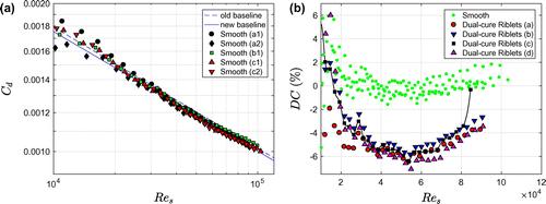
Figure 5. Drag change data for cylinders coated with Modified Intersleek® Riblets and Dual-cure Riblets. (a) Drag change as a function of the shear Reynolds number for four cylinders coated with Modified Intersleek® Riblets. The data for the smooth cylinders are also included. (b) Drag change as a function of the shear Reynolds number for the best-performing Dual-cure and Modified Intersleek® Riblet coatings.
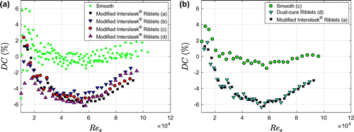
The drag change for the Dual-cure Riblets (Figure b) and the Modified Intersleek® Riblets (Figure a) is very similar. The measurements are quite reproducible for both coating types, with a variability around the average of about ± 1 percentage point. All four replicates of the Dual-cure Riblets demonstrate about 6% drag reduction. Coating (c) detached partly at the seam of the foil at the penultimate rotation rate, as is apparent from the sudden drag increase. The maximum drag reduction of the Modified Intersleek® Riblets varies between 5.2% and 6.2% (Figure a). The final comparison between the two riblet types is presented in Figure b. The best-performing coatings of each type were selected and measured again in one week. A smooth dataset, obtained in the same week, is included. The data for the Dual-cure and Modified Intersleek® Riblet coatings coincide almost perfectly. The maximum drag reduction is 6.3% for the Dual-cure Riblets and 6.2% for the Modified Intersleek® Riblets.
Barnacle settlement assay
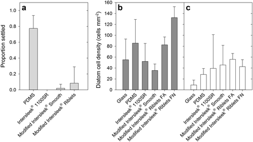
Barnacle cyprid settlement on all Intersleek® 1100SR surfaces (with and without riblets) was minimal (Figure a), despite high settlement on PDMS (~ 80%). The observed settlement on Modified Intersleek® Smooth was entirely composed of a small amount of settlement (14%) on one replicate. Similarly, only one replicate of the riblet-embossed coating showed any cyprid settlement, albeit at a somewhat higher level (59%).
Figure 6. Laboratory fouling assay results. (a) Mean proportion of barnacle (B. amphitrite) cyprids settled after 48 h on each surface type. The number of replicate microscope slides n was 7 for Modified Intersleek® with and without riblets, 6 for PDMS and 3 for Intersleek® 1100SR. Error bars are+95% confidence intervals. (b) Mean diatom (N. incerta) cell density for slides not exposed to hydrodynamic shear; (c) mean diatom cell density for slides exposed to shear (~38 Pa, 5 min). For (b) and (c) n = 2 for Intersleek® 1100SR and n = 3 for all other surfaces. All error bars are+95% confidence intervals.
Diatom adhesion and ease-of-removal assay
The initial density of adhered diatoms (without exposure to shear stress) varied significantly among surfaces (ANOVA, F = 28.334, p < 0.001). Modified Intersleek® Riblets FN had significantly greater diatom density (Figure b) than all other surfaces (Tukey test, p < 0.01), and the Modified Intersleek® Riblets FA surface had greater diatom density than the same formulation without the riblets (Tukey test, p < 0.01). Exposure to shear stress resulted in a significant reduction in diatom density on glass (t = 5.097, df = 4, p < 0.01), PDMS (t = 5.508, df = 4, p < 0.01), and both Modified Intersleek® surfaces with riblets (FA riblets, t = 6.383, df = 4, p < 0.01; FN riblets, t = 16.241, df = 4, p < 0.0001). There was no significant reduction in diatom density on either standard Intersleek® 1100SR (Welch’s t = 2.195, df = 1.5, p = 0.099) or Modified Intersleek® Smooth (t = –1.141, df = 4, p = 0.84). There was still significant variation among surfaces after exposure to shear (Figure c, ANOVA, F = 13.933, p < 0.001); glass had lower cell density compared to all Intersleek® 1100SR-based samples (Tukey tests, p < 0.01), but there were no significant differences in final cell density (post-shear) between any of the Intersleek® 1100SR variants (Tukey tests, p > 0.05).
Biofilm growth and release testing
Four surfaces were assessed, namely Intersleek® 1100SR, Modified Intersleek® Smooth, Modified Intersleek® Riblets FA (riblets parallel with the flow) and Modified Intersleek® Riblets FN (riblets perpendicular to the flow). The test surfaces all showed high levels of fouling, close to 100% cover, after 49 days of immersion in the biofilm culturing reactor. There was no significant variation among surfaces in percentage cover (ANOVA, F(3,20) = 1.797, p = 0.180).
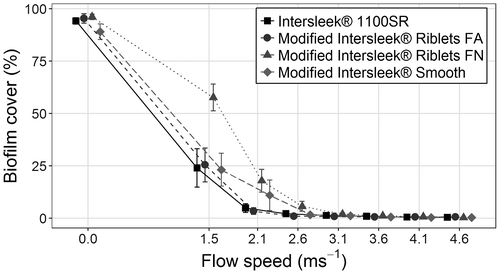
All surfaces underwent biofilm removal testing in the flow cell (Figure ). After exposure to a flow speed of 1.5 m s−1 there was significant variation among coatings (ANOVA, F(3,20) = 4.445, p = 0.015); Intersleek® 1100SR, Modified Intersleek® Smooth and Modified Intersleek® Riblets FA all retained ~23–25% of biofilm, whilst Modified Intersleek® Riblets FN had ~58% of biofilm (Figure ). This pattern remained after exposure to a flow speed of 2.1 m s−1 (ANOVA using square-root transformed data, F(3,20) = 3.443, p = 0.036), but any variation after exposure to 2.6 m s−1 was not statistically significant (ANOVA using square-root transformed data, F(3,20) = 1.923, p = 0.158). At a flow speed of 3.1 m s−1 nearly all visible biofilm had been removed, with <2% remaining on any of the surfaces. At the maximum flow speed (4.6 m s−1) < 1% biofilm remained on any tested surface. Data for flow speeds of 3.1 m s−1 and greater were not analysed statistically because of extremely low levels of biofouling, and failure to meet necessary assumptions for statistical testing.
Figure 7. Biofilm removal testing using the hydrodynamic flow-cell. Six coated slides are shown for each flow speed and coating type. The flow is from left to right. Riblets FA are parallel to the flow, whereas Riblets FN are perpendicular to the flow.
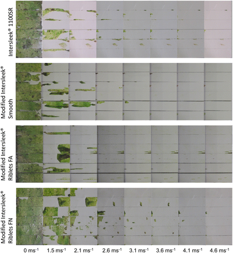
Figure 8. Biofilm release performance of test surfaces under flow conditions. Data are mean percentage biofilm cover (± SE) remaining after exposure to increasing flow speeds. Points have been horizontally offset for clarity of presentation; all surfaces were tested at the same speeds, as indicated on the x-axis. For all surfaces n = 6.
Field immersion testing
After three weeks in Hartlepool Marina, the surfaces were only fouled with microfouling and weed (Figure b). There was significant variation in percentage cover among the surfaces (ANOVA, F(5,30) = 11.668, p < 0.001). Both riblet-embossed Intersleek®s had a higher percentage cover (> 80%) compared to unmodified Intersleek® 1100SR and brush-applied Modified Intersleek® Smooth (Holm–Sidak, p < 0.05), while having a similar percentage cover to PDMS (Holm–Sidak, p > 0.05). PDMS, however, had a greater percentage cover of weed compared to the riblet-embossed Intersleek®s (ANOVA, comparison of weed cover including only PDMS and the surfaces with riblets, F(2,15) = 6.101, p = 0.012, Holm–Sidak tests: p < 0.05 for comparisons between PDMS and riblet surfaces, and p = 0.907 for comparison between the two riblet orientations).
Figure 9. Results of field immersion testing. (a) Example of six coated squares on the panel after six weeks immersion in Changi, Singapore; (b) mean percentage cover of biofouling on test surfaces after three weeks immersion in Hartlepool Marina, UK; (c) mean percentage cover of biofouling on test surfaces after one week (left bars) and six weeks (right bars) immersion in Changi Marina, Singapore. IS = Intersleek® 1100SR; MIS = Modified Intersleek® Smooth (doctor-blade applied); MISB = Modified Intersleek® Smooth (brush applied); MIRV = Modified Intersleek® Riblets Vertical; MIRH = Modified Intersleek® Riblets Horizontal; PDMS = polydimethylsiloxane.
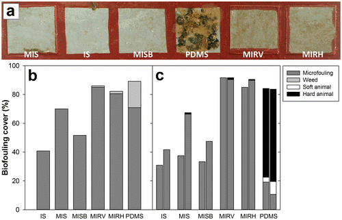
Differences among surfaces were somewhat greater after deployment in Singapore (Figure a and c). After immersion for only one week, there was a significantly higher overall fouling cover on the riblet surfaces and PDMS, compared to the Intersleek® variants without riblets (ANOVA, F(5,30) = 20.279, p < 0.001. Holm–Sidak tests: p < 0.001 for comparisons between riblet coatings and smooth Intersleek®s, p > 0.9 for comparisons between the two riblet orientations and PDMS, and p > 0.9 for comparisons between the different smooth Intersleek® variants). PDMS was, however, differentiated from the two riblet-embossed surfaces by a high proportional cover (61.7%) of hard animal biofouling (eg barnacles and tubeworms); at this time point there was no animal fouling on any of the Intersleek® variants.
After six weeks the pattern was broadly similar, with significant variation in the overall percentage cover among surfaces (ANOVA, F(5,30) = 26.264, p < 0.001). Again, the surfaces were generally divided into two groups on the basis of percentage cover; the riblet surfaces and PDMS had higher percentage cover (> 80%), while standard Intersleek® 1100SR and brush-applied Modified Intersleek® Smooth had < 50% overall biofouling cover (Holm–Sidak, p < 0.001 for comparisons between riblet coatings and Intersleek® 1100SR/brush-applied Modified Intersleek® Smooth, p > 0.5 for comparisons between the two riblet orientations and PDMS, and p = 0.566 for comparison between Intersleek® 1100SR and brush-applied Modified Intersleek® Smooth). Doctor-blade-applied Modified Intersleek® Smooth had an intermediate level of fouling cover (67.3%). PDMS was again distinguished from the riblet surfaces by a high proportional cover of hard fouling organisms: 64.2% compared to <2% hard fouling on the riblet-embossed Intersleek® formulations. This is consistent with the trend observed in the barnacle settlement assays (Figure a).
Discussion
Manufacturing
The embossing-curing technology in principle allows the manufacturing of drag-reducing paints on large surfaces. Some of the remaining hurdles to full-scale application are the time and cost of paint application, the large-scale application to curved surfaces and performance degradation due to wear (Viswanath Citation2002). Wear might be especially a concern for the Modified Intersleek® Riblets. Whereas the Dual-cure Riblets were designed for durability with respect to airborne particulate erosion in aerospace applications, the Modified Intersleek® Riblets are softer and possibly more prone to damage than the Dual-cure Riblets. However, the particulate velocities are lower in maritime as compared to aerospace applications. In addition, previous Intersleek® coating systems have been sufficiently robust to survive use on commercial ships for multi-year in-service periods, such that erosion may not be a significant issue in practice.
Hydrodynamic drag measurements
The data for different cylinders with the same coating type show some scatter. This might be due to several factors such as: (1) uncertainty in the torque measurements (especially for low shear Reynolds number for which the torque is very small), (2) slight variations in the cylinder geometries, surface smoothness and coating thickness, (3) slight differences in alignment of the cylinders in the set-up, in particular slight variations in the heights of the Von Kármán gaps. The drag variation for Res > 3 ⋅ 104 is typically ± 1%, which is hence used as an estimate for the uncertainty of the drag measurements.
Instead of a smooth cylinder, unmodified Intersleek® 1100SR could have been used as the reference surface, since the as-applied untextured AF/FR coating would give the baseline drag in practice. For that reason, the drag of Intersleek® 1100SR coatings was also measured in the same Taylor–Couette set-up, but it was not significantly different from the drag of a smooth, uncoated surface. Hence, DC would not change if the reference drag was based on Intersleek® 1100SR. The uncoated cylinders were used for the baseline for three reasons, namely to compare the results with previous measurements by Greidanus et al. (Citation2015), to save the effort of coating extra cylinders, and to limit the additional variability between the reference surfaces that would have been introduced by the coating application method.
The Dual-cure and Modified Intersleek® Riblets showed the same drag-reducing performance: the maximum drag reductions of 6.3% (Dual-cure) and 6.2% (Modified Intersleek®) are the same within the experimental uncertainty of ± 1 percentage point. Hence, the use of Modified Intersleek® to manufacture riblet coatings did not significantly compromise the drag-reducing potential of such textured coatings. Although the Modified Intersleek® Riblet texture is much softer compared to the Dual-cure Riblets, it is presumably stiff enough such that it does not significantly deform in the turbulent Taylor–Couette flow. The maximum drag reduction is about 6%, which is <7.8% reduction obtained by Bechert et al. (Citation1997) for comparable riblets with a tip angle of 45 degrees. This is possibly due to the curved flow geometry in the Taylor–Couette set-up, which is different from the plane flow geometry in Bechert’s work. The figure of 6% drag reduction will need to be confirmed by future work, for example using flat plates.
Barnacle settlement assay
The riblet pattern did not appear to substantially reduce the ability of Intersleek® 1100SR to prevent fouling by cyprids of B. amphitrite, which is in agreement with previous work showing that a similar riblet pattern actually reduced settlement of barnacle (B. improvisus) cyprids (Berntsson et al. Citation2000). Settlement on the riblet-embossed Intersleek® surface seemed to be slightly increased relative to the smooth surface, but this was entirely the result of one replicate slide with some settlement; the other six replicates of the riblet surface had no settlement. Barnacles (including B. amphitrite) settle gregariously (Knight-Jones Citation1953; Clare and Matsumura Citation2000), and it is possible that settlement of a single barnacle (attaching, for example, to a surface defect or sample contaminant) could have induced settlement of multiple barnacles on a single replicate. However, given the inherent fouling-control properties of the Intersleek® 1100SR surfaces, it was not possible to induce enough settlement or growth of barnacles on the riblet surfaces to conduct any tests of the FR properties against juvenile and adult barnacles.
Diatom adhesion and ease-of-removal assay
The initial attachment density of diatoms was significantly higher on the riblet surfaces compared to smooth Intersleek® 1100SR. However, after exposure to shear, the final cell density was very similar across all Intersleek® 1100SR surfaces, regardless of the presence or orientation of a riblet structure. This indicates that the additional diatoms present on the riblet surfaces were all removed under flow. Few diatoms were removed from the smooth Intersleek® surfaces by hydrodynamic shear, which is in agreement with previous literature indicating that N. incerta biofilms are highly tenacious on silicone-elastomer-based fouling-release coatings (Holland et al. Citation2004). This suggests that in addition to a similar density of strongly-adhered cells, the riblet coatings initially retained a higher density of more loosely adhered cells within the riblet pattern, which were then readily removed under shear stress.
For suitable applications (eg fast moving vessels) this may mean that the overall performance of Intersleek® 1100SR against diatoms is not worsened by the riblet pattern. However, for other applications (eg slower vessels) where shear stresses are not sufficient to remove the loosely attached cells, the riblet structure may increase the accumulation of diatomaceous biofilms, resulting in the loss of any hydrodynamic advantage conferred by the riblet pattern.
It is not clear why the FN riblet surfaces, in the absence of shear exposure, had a higher density of diatom cells compared to the FA riblet surfaces. The material used and the riblet pattern were the same, and the slides were treated identically during the diatom assay. However, the slides with the two riblet orientations were manufactured on different dates, so it is possible that there was some small difference in the paint or the manufacturing process. Since the density of cells after shear exposure was the same as for all the other Intersleek® surfaces, this difference did not have an important effect on the overall outcome.
Biofilm growth and release performance and field immersion testing
There was no significant difference in the resistance of the different Intersleek® formulations to colonisation by biofilms in the biofilm culturing reactor; the semi-natural biofilms covered almost 100% of all the slides.
Greater differentiation was observed in the field immersion tests. When brush-applied, the Modified Intersleek® formulation performed similarly to the unmodified Intersleek® 1100SR. The doctor-blade-applied version acquired more biofouling after three weeks in Hartlepool Marina or six weeks in Changi Marina. However, there was no difference between Intersleek® 1100SR and its modified variant in the release tests, indicating that the modifications to make the formulation compatible with riblet manufacturing did not reduce the biofilm release properties.
The addition of riblets appeared to somewhat reduce the fouling-control performance in the field tests. Surfaces with riblets generally acquired greater biofilm cover, and even a small amount of hard-animal fouling in Singapore. Although the riblet surfaces had similar fouling cover compared to PDMS, the fouling composition was different. The textured surfaces acquired less weed (Hartlepool) and less animal fouling (Changi) than PDMS. As weed and animal fouling have a considerable drag impact (Schultz Citation2007), the riblet-embossed surfaces would be expected to have an improved hydrodynamic performance compared to PDMS.
Riblets orientated parallel to the water flow direction (FA) demonstrated no reduction in the release of biofilm under shear when compared to Modified Intersleek® Smooth. There was a minor reduction in release performance when the riblets were orientated perpendicular to the flow direction (FN). However, the intended use of the riblets is aligned with the flow direction; riblets perpendicular to the flow yield a drag increase.
Conclusions and future work
This study shows that an existing FR coating can be modified to produce a structured drag-reducing surface without substantially compromising its short-term fouling-control or drag-reducing performance. The riblet pattern did not substantially increase barnacle settlement, although diatom adhesion and field immersion tests did demonstrate that riblets can facilitate the growth of biofilms compared to untextured surfaces. When exposed to flow, however, differences in FR properties were not observed.
Future work should focus on the potential benefit of modified Intersleek® riblets to moving vessels. There is no obvious advantage to the use of riblets under stationary conditions, as these can increase settlement and growth of biofilms. In addition, riblets are designed to reduce the drag in turbulent flow, which requires motion of the riblet surface through a fluid. In turn, the accumulation of fouling might also be different when the vessel is sailing at the specific speed for which the riblets are drag-reducing.
The design and practical application of optimised riblet coating systems to commercial ships still presents a number of obvious challenges and the maximum drag reduction of 6% seen for riblet coatings under controlled laboratory conditions may therefore not be achieved in practice. Nevertheless, even a small reduction in drag will potentially provide significant economic and environmental benefits.
It is especially important to investigate whether the texture would stay clean and intact during normal use on an appropriate vessel. If the texture is rapidly lost through fouling or wear, then the drag-reducing properties will be lost as well and the application of riblets would not be beneficial. Demonstration of the long-term stability and FR performance of the riblet-textured Modified Intersleek® under in-service conditions is the next logical step towards the implementation of the technology for shipping applications, which may contribute to meeting the IMO requirements on emissions reduction on ships.
Funding
The research leading to these results has received funding from the European Union Seventh Framework Programme in the SEAFRONT project [grant agreement number 614034]. Additional support for supply and culture of organisms used for biological testing at Newcastle University was received from the Office of Naval Research [grants N00014-13-1-0633, N00014-13-1-0634 to ASC].
Disclosure statement
No potential conflict of interest was reported by the authors.
Acknowledgements
The authors would like to thank K. Eiben for skilful riblet manufacturing and A.J. Greidanus for help with the Taylor–Couette measurements.
References
- Bechert DW, Bruse M, Hage WV, Van der Hoeven JT, Hoppe G. 1997. Experiments on drag-reducing surfaces and their optimization with an adjustable geometry. J Fluid Mech. 338:59–87. doi:10.1017/S0022112096004673.10.1017/S0022112096004673
- Berntsson KM, Jonsson PR, Leijhall M, Gatenholm P. 2000. Analysis of behavioural rejection of micro-textured surfaces and implications for recruitment by the barnacle Balanus improvisus. J Exp Mar Biol Ecol. 251:59–83. doi:10.1016/S0022-0981(00)00210-0.10.1016/S0022-0981(00)00210-0
- Clare AS, Matsumura K. 2000. Nature and perception of barnacle settlement pheromones. Biofouling. 15:57–71. doi:10.1080/08927010009386298.
- Dean B, Bhushan B. 2010. Shark-skin surfaces for fluid drag reduction in turbulent flow: a review. Phil Trans R Soc A. 368:4775–4806. doi:10.1098/rsta.2010.0201.10.1098/rsta.2010.0201
- Department for Transport (UK). 2017. Shipping fleet statistics 2016. Department for Transport, UK [accessed 2017 November 01]. https://www.gov.uk/government/statistics/shipping-fleet-statistics-2016
- Finnie AA, Williams DN. 2010. Paint and coatings technology for the control of marine fouling. In: Dürr S, Thomason JC, editors. Biofouling. Oxford: Wiley-Blackwell; p. 185–206.
- Greidanus AJ, Delfos R, Tokgoz S, Westerweel J. 2015. Turbulent Taylor-Couette flow over riblets: drag reduction and the effect of bulk fluid rotation. Exp Fluids. 56:1–13.
- Hellio C, Marechal J-P, Véron B, Bremer G, Clare AS, Le Gal Y. 2004. Seasonal variation of antifouling activities of marine algae from the Brittany coast (France). Mar Biotechnol. 6:67–82. doi:10.1007/s10126-003-0020-x.
- Hellio C, Simon-Colin C, Clare AS, Deslandes E. 2004. Isethionic acid and floridoside isolated from the red alga, Grateloupia turuturu, inhibit settlement of Balanus amphitrite cyprid larvae. Biofouling. 20:139–145. doi:10.1080/08927010412331279605.
- Holland R, Dugdale TM, Wetherbee R, Brennan AB, Finlay JA, Callow JA, Callow ME. 2004. Adhesion and motility of fouling diatoms on a silicone elastomer. Biofouling. 20:323–329. doi:10.1080/08927010400029031.
- Knight-Jones EW. 1953. Laboratory experiments on gregariousness during setting in Balanus balanoides and other barnacles. J Exp Biol. 30:584–599.
- Kordy H. 2015. Process abilities of the riblet-coating process with dual-cure lacquers. CIRP J Man Sci Tech. 11:1–9.
- Lejars M, Margaillan A, Bressy C. 2012. Fouling release coatings: a nontoxic alternative to biocidal antifouling coatings. Chem Rev. 112: 4390.
- Longyear J. 2014. Chapter 7, Section 2. Mixed population fermentor. In: Dobretsov S, Williams DN, Thomason JC, editors. Biofouling methods. Oxford: John Wiley & Sons Ltd; p. 214–219.
- Ring K. 2000. Recruitment of Balanus improvisus on micro-textures with different geometries and evaluation of methods for analyzing cyprid behaviour [Master’s thesis]. Sweden: Göteborg University.
- Schneider CA, Rasband WS, Eliceiri KW. 2012. NIH Image to ImageJ: 25 years of image analysis. Nat Methods. 9:671–675. doi:10.1038/nmeth.2089.10.1038/nmeth.2089
- Schultz MP. 2007. Effects of coating roughness and biofouling on ship resistance and powering. Biofouling. 23:331–341. doi:10.1080/08927010701461974.10.1080/08927010701461974
- Schultz MP, Flack KA. 2013. Reynolds-number scaling of turbulent channel flow. Phys Fluids. 25:025104. doi:10.1063/1.4791606.
- Schultz MP, Finlay JA, Callow ME, Callow JA. 2000. A turbulent channel flow apparatus for the determination of the adhesion strength of microfouling organisms. Biofouling. 15:243–251. doi:10.1080/08927010009386315.
- Smith TWP, Jalkanen JP, Anderson BA, Corbett JJ, Faber J, Hanayama S, O’Keeffe E, Parker S, Johansson L, Aldous L, et al. 2015. Third IMO GHG Study 2014. London: International Maritime Organization (IMO).
- Stenzel V, Wilke Y, Hage W. 2011. Drag-reducing paints for the reduction of fuel consumption in aviation and shipping. Prog Org Coat. 70:224–229. doi:10.1016/j.porgcoat.2010.09.026.10.1016/j.porgcoat.2010.09.026
- Stenzel V, Schreiner C, Brinkmann A, Stübing D. 2016. Biomimetic approaches for ship drag reduction – feasible and efficient? In: Bertram V, editor. HIPER 2016. Proceedings of the 10th Symposium on High-Performance Marine Vehicles; Oct 17-19. Cortona. p. 131–140.
- Viswanath PR. 2002. Aircraft viscous drag reduction using riblets. Prog Aerosp Sci. 38:571–600. doi:10.1016/S0376-0421(02)00048-9.10.1016/S0376-0421(02)00048-9
- Woods Hole Oceanographic Institution. 1952. Marine fouling and its prevention. Annapolis (MD): United States Naval Institute.
- Yebra DM, Kiil S, Dam-Johansen K. 2004. Antifouling technology—past, present and future steps towards efficient and environmentally friendly antifouling coatings. Prog Org Coat. 50:75–104. doi:10.1016/j.porgcoat.2003.06.001.10.1016/j.porgcoat.2003.06.001
