Abstract
This article presents an analytical model, originally developed in the 1980s, for the gas centrifuge and uses this methodology to determine the main design and operational characteristics of several hypothetical centrifuge designs. A series of simulations for a typical first-generation machine is used to assess the relevance of important breakout scenarios, including batch recycling and cascade interconnection, using either natural uranium or preenriched material as feedstock.
INTRODUCTION
The gas centrifuge for uranium enrichment is playing an increasingly important role in the civilian nuclear fuel cycle. A major concern from the viewpoint of nuclear nonproliferation is the possibility of converting a civilian enrichment facility into one that produces highly enriched uranium (HEU). In the case of a “breakout” scenario, in which the production of HEU for weapon purposes is pursued, this is done as rapidly as possible, without making efforts to conceal intentions or actions. Understanding the potential for breakout clearly involves detailed technical knowledge of the functioning of centrifuges and the cascades built out of them.
The determination of the main characteristics of the gas centrifuge for uranium enrichment is a challenging task for several reasons. Analytically, two entirely independent problems have to be solved: the profile of the gas flow in the machine is determined by the hydrodynamic equations, whereas the separation phenomena are governed by the diffusion equations. In order to execute the separative analysis, the solution to the hydrodynamic problem has to be available. In practice, however, the solution process is reversed, and analysts simply assume an idealized or optimum flow profile and determine the separative performance of the machine. The challenge is then to join the two parts of the analysis in a meaningful way.Citation 1 Analytical approaches are also challenged by the impact of perturbations, such as those caused by the presence of scoops and baffles or by the acceleration of the injected feed—effects that may not be negligible for realistic machines. Finally, research and development on centrifuges has been classified since 1960. There is therefore little data available to validate and explore the limits of approaches described in the open technical literature on centrifuges.
THE 1983 ANALYTICAL SOLUTION BY E. RÄTZ
An excellent derivation of physical principles of the gas centrifuge for uranium enrichment available in the open literature is the one developed by Ernst Rätz in the early 1980s. It emphasizes the separative analysis using a so-called two-shell approach for the axial flow profile to represent the hydrodynamics of the problem. In its most comprehensive form, this analysis has been published as a Ph.D. thesis.Citation 2
The derivation starts off with the partial differential equation for the gas centrifuge for the fractional concentration N(r,z) of the isotope of interest, following the notation of Cohen.Citation 3 The most general form of the equation simplifies for isothermal, equilibrium conditions (∂ N/∂ t = 0) with vanishing net radial drift velocity of the gas.
Here, a is the radius and v a the peripheral velocity of the centrifuge rotor; p(r) is the local gas pressure; and w(r,z) the axial velocity of the gas. For a binary mixture of U-235 and U-238 in the process gas, Δ M = 0.003 kg/mol. R is the universal gas constant, and T is the average temperature of the gas. The coefficient of self-diffusion D is proportional to 1/ρ and D ρ = const. For a specified temperature and as long as the ideal gas law applies, the product D p is equally constant.
In the centrifuge Eq. (Equation1), the first two terms describe separation phenomena due to radial pressure and back-diffusion. The last two terms account for phenomena related to the axial current in the rotor and axial back diffusion.
The equation can be integrated with selected additional assumptions. For tall rotors (Z ≫ a), the second-order effect of axial back diffusion is small and therefore typically ignored. The solutions proposed by Cohen and Rätz, however, differ in one important aspect. Cohen had originally posited that ∂ N/∂ z only weakly depends on the radius and assumed this function constant for the radial integration, which significantly simplifies the solution.Citation 4 In contrast, Rätz shows that this assumption does generally not hold. He therefore introduces a two-shell flow profile, in which average values for ∂ N/∂ z are defined separately for the inner and outer shells of the flow profile. The selection of the radii (r 1 and r 2) will be discussed further below. Ultimately, Rätz derives an analytical expression for the difference in isotope concentration (N P − N W ) at both ends of a machine of length Z operated in the countercurrent mode as a function of variables that are either selected in advance or to be optimized later on.Citation 5
Selection of the Two-Shell Radii
The remaining variables needed to evaluate the separative performance of the machine are the radii r 1 and r 2 of the equivalent two-shell profile. Rätz indicates that these radii have to be “chosen in a sensible manner,” such that they bisect the mass flows in the respective streams as illustrated in .
Figure 1 Typical mass-velocity profile expected for a centrifuge.
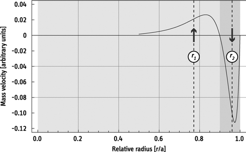
The radial dependency of the mass flow or mass velocity profile ρ(r) w(r), where ρ is the density and w the axial velocity of the gas, is generally unknown. It requires solution of the hydrodynamic equations, which are—as already pointed out above—entirely independent from the separation phenomena in the machine. Good estimates for r 1 and r 2 are important for a sound estimate of machine performance. In general, the designers will try to maximize the effect of elementary (radial) separation by channeling the product flow through the interior of the machine, but this strategy may be limited by the low pressure in this region. Rätz shows that the optimum withdrawal radii ratio is obtained when the following expression is maximal:Citation 7
For various practical purposes, however, the effective withdrawal radius is also constrained by a pressure ratio x of, say, 1000:1. For fast machines, the radii ratio r 1/r 2 will be determined by this pressure ratio rather than by condition (Equation4). Using the fundamental barometric equations for the radial pressure distribution in the machine, one obtains:Citation 8
Here, M is the molar weight of the process gas UF6 (0.352 kg/mol), and all other variables have been defined previously. For typical temperatures and for x = 1000, the optimum radii ratio from Eq. (Equation4) can be exploited for peripheral velocities of up to about 380 m/s; beyond that value, Eq. (Equation5) determines a practical value for the ratio. illustrates how r 1/r 2 changes with rotor velocity.
Figure 2 Optimum withdrawal radii ratio as a function of peripheral velocity.
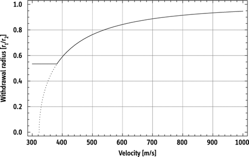
As a result of this effect, i.e., the emptying of the interior of the machine, the performance of very fast centrifuges only increases with δ U ∼ v 2 instead of δ U ∼ v 4, which is theoretically predicted by Dirac's solution for the maximum separative performance of a centrifuge:Citation 9
Separative Power
The separative power of an enriching unit is generally defined as:
with A P (L,F,θ) and A W (L,F,θ) as previously defined. Equation (Equation10) is the main analytical result to be used below to determine the performance of centrifuges. Note that it is not necessary to define the value function itself for this derivation of δ U. Based on the definition of V”(N) from Eq. (Equation8), a solution for V(N) can be specified. This standard expression will be used later on in the analysis.
The separative power δ U as defined in Eq. (Equation10) is a function of the countercurrent, feed rate, cut, and rectifier length. Other parameters of the machine are selected in advance, but they could be treated as variables as well. These are the radius of the rotor a, the peripheral velocity v a , the total length of the rotor Z, and the mean operating temperature T. The radii r 1 and r 2 have to be adjusted if the velocity is varied. The position of the feed point, i.e., the rectifier length, would also be selected in the design stage of the machine. An analysis shows that the optimum rectifier length Z P ✶ depends on the countercurrent-to-feed ratio L/F and the cut θ and is given by the following expression.Citation 11
Separation Factor
Maximizing the separative power δ U of a centrifuge is the primary objective of the design and optimization process. As will be shown below, however, the optimum δ U can be obtained—and a machine be operated—for a broad range of feed rates depending on the magnitude of the countercurrent established in the machine.
Once the separative power of the machine has been characterized as a function of all design and operational parameters, the net effect on the feed material can be quantified by the enrichment factor α and the depletion factor β.
DESIGN AND PERFORMANCE CHARACTERISTICS OF SELECTED EXISTING MACHINES
Several centrifuge designs have played important roles historically as a “base design” for further development or replication elsewhere. Other machines are commercially used today or are being developed for use in new centrifuge facilities under construction or planned in Brazil, Iran, France, and the United States. lists estimated design characteristics of important centrifuge generations, and the discussion below provides some background information on selected machines, explaining some of the estimated values listed here. For convenience, the common shorthand notation (P-1, P-2, etc.) is used to refer to some of these machines.
P1-type: The P-1 is based on early Dutch designs, designated SNOR and CNOR (scientific and cultivated nuclear orbital rotor),Citation 12 which were developed in the initial phases of the Urenco project and used in the Dutch pilot plant SP1. The rotors of the original Dutch machines consisted of six segments, whereas the P-1 apparently only uses four, reducing its length to slightly less than 2 m. Each segment is said to contribute 0.5 SWU/yr to the overall separative power of the CNOR and the P-1 design.Citation 13 All designs use aluminum rotors, which limits the peripheral velocity to about 350 m/s. A rotor diameter between 10 cm and 11 cm has been reported for the P-1.Citation 14 In an interview from April 2006, an Iranian official corroborated many details of the P-1 (IR-1) design: accordingly, its rotor length is 180 cm, the rotor diameter 10.5 cm, and the peripheral velocity 350 m/s.Citation 15 The rotor length is also consistent with pictures of cascades installed in the Iranian pilot and fuel enrichment plants. | |||||
P2-type: Based on publicly available information, the P-2 is a slightly modified version of the G-2 centrifuge. The G-2 itself was a German pre-Urenco design using a maragaing steel rotor with two segments.Citation 16 The G-2 is a supercritical machine and is twice as long as an earlier, subcritical one-segment machine (G-1). The widely reported rotor length of 1.0 m for the G-2 and the P-2 is consistent with available pictures of the original machine. Values between 14.5 cm and 15.0 cm have been reported for the rotor diameter of the G-2.Citation 17 The G-2 was used in the German pilot plant SP2 and in the Dutch demonstration plant B21. The use of high-strength maraging steel for the centrifuge rotor allows peripheral velocities of up to 500 m/s. As a reference value, a velocity of 485 m/s is used in for most maraging steel machines. The separative power of the P-2 is estimated to be 5–6 SWU/yr. | |||||
Publicly available information on other machines listed in is more uncertain. Features can be estimated, however, based on known characteristics of older machines and the relative improvements made compared to them. The design and performance data—and, in fact, even the very existence—of the advanced Pakistani centrifuges P-3 and P-4 largely based on reports by M. Hibbs.Citation 18 The key hypothesis is that both machines are again based on designs studied by Urenco in the late 1970s and early 1980s.
P3-type: According to a Dutch government report, Pakistani scientist A.Q. Khan may have had access to the design of an advanced centrifuge, designated 4-M, which had been under development in The Netherlands in the early 1970s.Citation 19 Available information suggests that the 4-M is a four-segment machine, about 2 m tall,Citation 20 and presumably based on a maraging steel rotor. The separative power of the P-3 has been quoted as just under 12 SWU/yr.Citation 21 | |||||
P4-type: Western intelligence data suggest that Pakistan developed an advanced centrifuge in the mid-1980s. Accordingly, this machine is based on a Durch Urenco design, designated SLM, later known as the TC-10.Citation 22 Reportedly, the rotor has a diameter of 14.5 cm, a length of 3.2 m, and is operated at 508 m/s. The separative performance of the P-4 has been quoted as 21 SWU/yr. | |||||
Additional machines are listed in to illustrate the potential of advanced centrifuge technology. Estimates for Urenco machine design and performance parameters are based on information published by Urenco in several briefings and articles.Citation 23 The documents feature graphs illustrating the separative power, peripheral velocity, and rotor length of Urenco machines in relative units as a function of the centrifuge generation. Data points that are known with reasonable confidence are available to deduce absolute values for the axes. Specifically, the performance of the TC-12, a fourth-generation machine, has been specified with 40 SWU/yr.Citation 24 Its length is often quoted as about 3 m. Similarly, the maximum velocity of all-metal (maraging steel) machines is limited to about 500 m/s. According to the published figures, the use of composites enabled a 1.2-fold velocity increase for third-generation machines and a 1.5-fold increase for the most advanced designs (sixth generation), which would then correspond to 600 and 750 m/s, respectively.
Table 1 Estimated design characteristics of important centrifuge generations.
Finally, estimated design and performance characteristics for the American Centrifuge (AC100) are listed. The developers of this machine, which is the candidate centrifuge for deployment in the new USEC enrichment facility, have specified many features of the machine. It is based on designs developed in the 1970s and early 1980s.Citation 25 The separative performance of the AC100 has been specified with 330–350 SWU/yr.Citation 26 Values for the length and diameter have also been reported.Citation 27 The known dimensions of the machine can be used for an estimate of the rotor speed that is consistent with the quoted performance of the AC100.
PERFORMANCE CHARACTERISTICS OF SOME HYPOTHETICAL MACHINES
Design data of various hypothetical centrifuges and their performance characteristics, as calculated with the formalism presented above, are summarized in . The maximum separative power for each machine can be determined with Eq. (Equation10) once the peripheral velocity and the rotor height and diameter are defined and an adequate combination of radii ratios is selected. The maximum performance δURaetz is achieved for a specific feed rate F✶. The optimum feed rate and, thus, the separation factor of the machine, however, varies with the selected countercurrent-to-feed ratio.
Table 2 Design and performance characteristics of hypothetical centrifuges. Equation (Equation6) determines the theoretical maximum performance δUDirac. The overall efficiency and the resulting effective separative performance δURaetz can be determined with Eq. (Equation10) once the radii ratio is selected. The optimum feed rate F✶ and the corresponding separation factor α β depend on the selected countercurrent-to-feed ratio k.
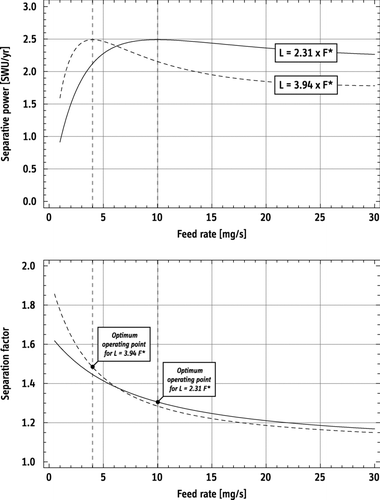
Typical countercurrent-to-feed ratios k range between 2 and 4. The value of k determines the optimum feed rate. For a given maximum separative power of the centrifuge, the effective separation factor then varies inversely with the feed rate. illustrates the dependencies for two design points of a P1-type machine. Accordingly, typical feed rates for the P-1 range between 4.0 and 13.5 mg/s, which corresponds to separation factors of 1.48 and 1.26, respectively.
Figure 3 Separative performance of a P1-type machine as a function of the feed rate for fixed internal circulation (top). Values for the countercurrent rates L have been chosen such that δ U is maximized for 10 mg/s (P1-100) and for 4 mg/s (P1-040). These design points are used for an analysis of cascade-performance below. The respective separation factors are also shown (bottom). Results based on the analytical model by Rätz using Eq. (Equation10).
SIMPLE MODEL OF TRANSIENT RESPONSE OF CENTRIFUGES
The equilibrium characteristics of centrifuges, including separative performance and reference feed rates, can be determined with the methodology presented above. A very simple mathematical model is used here to describe the transient behavior of the machine, which is based on the following main assumptions:
| • | The output rates of the machine (product and tails streams) are determined by the momentary UF6 inventory. In other words, even if the feed rate is gradually or abruptly changed, it will take some time before new output rates are established. In steady-state conditions, the UF6 inventory of the centrifuge and the corresponding wall pressure are therefore determined by the feed rate.Citation 28 | ||||
| • | The separative performance is determined by the momentary feed rate. In particular, if the internal circulation is maintained constant, the machine is operated at non-optimum conditions once the feed rate does not match its optimum value. The dependency is based on Rätz's analysis and is illustrated in . | ||||
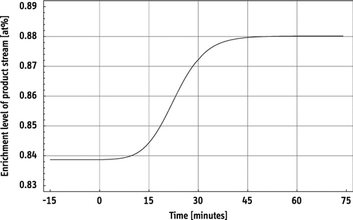
Once these quantities are calculated, the enrichment levels of the product and the tails leaving the machine can also be determined as a function of time. shows the response of a P1-type machine (P1-100) to a gradual decrease of the feed rate from its default value of 10 mg/s for the selected internal circulation to 5 mg/s. The assumed initial UF6 inventory is about 3.5 g, which is consistent with a wall pressure of about 100 torr.Citation 29 As evident from (top), the separative performance is degraded by less than 10%, even for such a 50% reduction of the feed rate. Accordingly, for example, the enrichment of the product leaving the machine increases, even for non-optimum operating conditions. In this example, new equilibrium conditions are reached within about one hour. This value is consistent with values derived with more advanced approaches to model the transient behavior of centrifuges, in which not only mass balances but also some physical phenomena are considered.Citation 30
Figure 4 Enrichment level of product stream leaving a P1-type centrifuge (P1-100). At t = 0, the feed rate is gradually reduced from its reference value of 10 mg/s to 5 mg/s over a 30-min period. The separative performance drops slightly from its optimum value (2.5 SWU/yr) to about 2.3 SWU/yr, if the internal circulation is not adjusted. A new equilibrium is obtained within about one hour. In this simulation, the feed material is natural uranium, and the cut is 0.46.
PERFORMANCE CHARACTERISTICS OF A 164-MACHINE CASCADE
Consider a default 164-machine cascade for an analysis of cascade performance and its response to feed characteristics (feed rate and feed enrichment). The design of this cascade, which is one basic building block of the Iranian enrichment program, can apparently be traced back to Pakistan and Germany.Citation 31 In the previously referenced 2006 interview,Citation 32 G. R. Aqazadeh specified further details of the cascade: accordingly, it is characterized by a total 15 stages; the feed is introduced in stage 5, which consists of 24 machines. The official also quantified the feed and product rates (70 and 7 g per hour, respectively) and a product enrichment of 3.5% that had been achieved at the time.Citation 33 The quoted product rate suggests that only one machine is present in the uppermost stage. With this information, and using the standard formulae for ideal cascades,Citation 34 a plausible cascade shape can be obtained ().
Figure 5 Possible arrangement of 164 machines in a 15-stage cascade.
The simulation of cascade characteristics and performance is based on Rätz's analytical solution for the machine performance from Eq. (Equation10) and the simple numerical model for the transient response of a centrifuge to changes in the feed rate and feed enrichment. These basic machine models permit simulation of a standard (symmetric) enrichment cascade, in which the product stream feeds into the next stage and the tails stream into the previous stage.Citation 35 Again, this cascade model is purely based on mass balances for total uranium and U-235, which are being transferred between stages. In the simulations, a cut of θ = 0.46 is used for all stages, which is close to the value for the ideal symmetric cascade.
The main results of all simulations are summarized in , which lists throughput and enrichment levels for several P1-type machines. Besides standard operation using natural uranium feed, enrichment levels for the first batch-recycling mode are also listed. Results are shown for machines used in this reference cascade that are each optimized for different feed rates.
Table 3 Results of the simulations for the 164-machine cascade using P1-type centrifuges. The four different modes of operation are each characterized by a specific optimum machine feed rate F✶, which translates into corresponding external feed rates and product rates and ultimately determines the enrichment level of the product leaving the cascade. The separative performance for the cascade (SP-C) and for an average machine (SP-AM) are shown. Values for batch recycling assume 3.5% enriched feedstock, initially produced with P1-135, and are taken after 120 hours of operation.
Variation of the feed rate, as expected, results in rather different enrichment levels that are obtained in this reference cascade. The simulations predict that an enrichment level of 3.5% is achieved with a machine feed rate of 13.5 mg/s (P1-135), whereas a reduced flow of 4.0 mg/s (P1-040) yields 5.7% enriched product. Two more candidate design points are listed. The annual throughput of the cascade scales directly with the feed rate. Annual production rates between 34 and 113 kg (net uranium) can be achieved with one 164-machine cascade using P1-type technology.
In addition to the the steady-state results for this cascade and the various machine-types, the transient response of the system to changes in the feed rate or feed enrichment (e.g., batch-recycling mode) is of particular interest. The result of such a simulation is shown in . Depending on the selected design point, which determines the optimum feed rate, a new equilibrium is reached within 24–48 hours for P1-type machines. These periods are short compared to the typical times relevant to a breakout scenario, as will be discussed in the next section.
Figure 6 Transient response of a 164-machine cascade using P1-type technology: Enrichment level of product in batch recycling mode, initiated at t = 0. Depending on the selected default feed rate, a new equilibrium is reached within 24–48 h.
Breakout-Scenario Assessment
The results of the simulations presented above can be used to determine the credibility and relative importance of various breakout scenarios. In this situation, the owner or operator of a safeguarded facility would abrogate agreements for peaceful use and produce highly enriched uranium for weapon purposes as rapidly as possible, without making attempts to conceal these intentions or actions.
Two different strategies are considered here: simple batch recycling and cascade interconnection with partial reconfiguration.Citation 36 The results will show that a complete reconfiguration of the cascades into a single one designed for HEU production is unnecessary: it does not increase the efficiency of the process and is likely to take longer than a partial reconfiguration. Both cases assume that a number of 164-machine cascades are initially available and that the material to be used for breakout is either natural uranium or a sufficiently sized stock of preenriched LEU (3.5%). The objective is the production of weapon-grade HEU with an enrichment level of 90% or more.
Batch Recycling
This is the crudest approach because significant amounts of enriched material are, at least temporarily, discarded in the process. The scenario assumes that the cascades themselves remain unmodified. Therefore, repiping is unnecessary, which may reduce the overall time needed to implement the strategy and may offset the inefficiency of the process itself. In order to further increase enrichment levels, the feed rates can be reduced in some or all of the cascades.
At least two batch cycles are needed to achieve enrichment levels of 90% or higher in a cascade originally designed to produce 3.5% enriched uranium from natural uranium. Cascade throughput in the first batch recycle should be as large as possible to provide sufficient feed for the second cycle. Based on the P1-type reference cascades listed in , one feasible option is to use the P1-135 cascade to go from 3.5 to 16.3%, and the P1-044 cascade from 16.3% to weapon-grade (91.1%). The transient response is shown in . The equilibrium time is on the order of 4 days; i.e., still small compared to the time required to do any repiping. Three P1-135 cascades are needed to produce feedstock for one P1-044 cascade. If natural uranium is used in a breakout scenario, then most cascades have to be operated to produce 3.5% enriched feedstock. Effective production rates and feed requirements are further summarized below.
Figure 7 Enrichment level of the product recovered from a 164-machine cascade of the second batch recyling step. The machines in this cascade are operated at a reduced flow rate (P1-044); feedstock is 16.3% preenriched material from a first batch recycling step, in which machines are operated at the standard flow rate (P1-135). In this simulation, the target enrichment level of 90% is reached after about 3.5 days.
Cascade Interconnection with Partial Reconfiguration
In this approach, which has historically been used by nuclear weapon states to produce weapon-grade uranium,Citation 37 a number of cascades are connected in series to form another cascade. The product of one cascade feeds into another one above, while the tails are recycled in a cascade below. Ideally, no material is discarded and no mixing occurs. The following assessment is based on a Pakistani cascade design, which was apparently proposed for the Libyan project to produce weapon-grade uranium. The South African court document referenced in note 31 specified:
The plant was designed to produce this material in three steps:
| • | Two cascades, C1 and C2, consisting of 1968 centrifuges each, would in parallel enrich natural uranium to 3.5%; | ||||
| • | The HC-01 cascade, consisting of 1312 centrifuges, would enrich the 3.5% material to 20%; | ||||
| • | The HC-02 cascade (456 centrifuges) would enrich the 20% material to 60% enrichment; | ||||
| • | The HC-03 cascade (128 centrifuges) would produce the final product, 90% enriched. | ||||
As noted, it is plausible to assume that the first set of cascades (C1 and C2) are expanded, but essentially identical versions of the standard 164-machine cascade: these cascades were designed for the same type of centrifuge (P-1), produced a typical enrichment level (3.5%), and use a multiple of 164 machines (12 × 164 = 1968). In contrast, all cascades of the HC-type, which represent about one third of the total number of machines (1896 out of 5832), generally require other cascade configurations.Citation 38 illustrates the configuration and further data on this enrichment strategy are summarized in . For the breakout scenario starting from natural uranium, the entire set of 5832 machines is used; for the scenario starting with preenriched feed, only the HC-type cascades are required.
Figure 8 Illustration of the cascade arrangement as proposed for the Libyan enrichment project. Note the asymmetric upstream and downstream connections. Mass values are normalized to one kilogram of product (weapon-grade uranium at 90% enrichment), which is produced in about 4.1 days with this setup, if based on P1-type technology.
Table 4 Feed materials required to produce 1 kg of weapon-grade uranium using cascade interconnection. The product enrichment levels for the sub-cascades are taken from the Libyan project as specified in the South African court documents. Product flows have been calculated here such that they match the required feed flow for the following cascade, while using not more than the assigned SWU/machine fraction. Accordingly, all HC-type cascades strip the tails down to natural uranium, which can be recycled back into the C1/C2 cascades. This strategy saves 31 kg of natural uranium and reduces the total demand to 280 kg per kilogram of weapon-grade uranium produced.
Batch Recycling versus Cascade Interconnection
Based on the data summarized in and , the effectiveness of both approaches can be compared. In each case, it is assumed that the starting point for breakout can either be natural or preenriched uranium. The main results are summarized in and .
Table 5 Summary of the breakout scenario starting from natural uranium. Values for the normalized production rates are for 6000 machines with a total separative capacity of about 15,000 SWU/yr. Batch recycling is extremely resource-intensive compared to cascade interconnection.
Table 6 Summary of the breakout scenario using 3.5% preenriched feed. Values for the normalized production rates are for 2000 machines with a total separative capacity of about 5000 SWU/yr. For the specified strategies, effective production rates would be slightly higher for the less efficient batch recycling mode, which needs a much larger supply of preenriched LEU (90 versus 32 kg per kilogram of weapon-grade uranium produced).
Breakout Starting with Natural Uranium.
This is the less credible scenario because enrichment of the 3.5% enriched material requires most of the capacity and could plausibly be carried out prior to breakout. The batch-recyling strategy is extremely inefficient compared to cascade interconnection because most of this feedstock will be discarded as tails in the subsequent batch cycles. Specifically, as shown in , batch recycling requires more than 100 times more uranium (33 tons compared to 280 kg per kilogram of the product) to produce less than half the amount of HEU.
Cascade interconnection produces 88.5 kg of weapon-grade uranium per year if a separative capacity of 2.5 SWU per year and centrifuge is assumed. A possible disadvantage of cascade interconnection compared to batch recycling would be the need to reconfigure about one third of the existing machines (1892 out of 5832). Given the extreme inefficiency of batch recycling, however, it seems implausible that this delay would offset the higher performance of interconnection, even if reconfiguration took several months.
Breakout with 3.5% Preenriched Feed.
Batch recycling becomes far more attractive if preenriched material is available because the large amounts of enriched uranium discarded in the process come at “no cost” (). The feed-to-product ratio is only about 3:1 compared to cascade interconnection and reasonably low in both cases. For the reference cases, the values are 90 kg and 32 kg of 3.5% enriched uranium per kilogram of HEU produced, respectively. Remarkably, the production rate is even higher for batch recycling when compared to cascade interconnection:Citation 39 Based on the output rates for the two relevant cascades (P1-044 and P1-135) summarized in , 105–110 kg of HEU are produced per year with 1968 machines arranged in 9 + 3 cascades. Note also that the minimum number of cascades needed in this batch recycling scenario is 656 machines (3 + 1 cascades) producing 35–37 kg of HEU per year, assuming 100% availability.
The cascade-interconnection approach, which is based on the three HC-type cascades from the Pakistani design using a total of 1896 machines, produces 88.5 kg of HEU per year, i.e., the same value that is obtained with natural-uranium feed and the complete set of cascades.Citation 40 If 164-machine cascades are initially available, the equivalent of 12 cascades has therefore to be reconfigured. In summary, given the comparable—and even higher—production rate for the batch recycling scenario, cascade interconnection is not necessarily the main concern for breakout with preenriched fuel.
CONCLUSION
This analysis has used an analytical approach, originally developed in the 1980s, to estimate design and performance characteristics of several hypothetical centrifuges, standing in for important centrifuge generations that have been developed and used as part of various research and development programs worldwide. Using a simple numerical model based on uranium mass balances, the transient response of both individual centrifuges and centrifuge cascades has been simulated. The results show that typical equilibrium times are small compared to the time required to produce significant quantities of enriched material.
The main objective of the analysis was to determine the credibility and relative importance of various breakout scenarios and to quantify the HEU production rates for them. Options that have been considered are simple batch recycling of preenriched material and cascade interconnection. A cascade design originally developed in Pakistan for HEU production with P1-type technology has been used to illustrate the significance of these results.
The results show that cascade interconnection is particularly effective if the production of weapon-grade uranium begins with natural uranium—which is not the most credible assumption for a breakout scenario but the default for a dedicated military enrichment program. In this case, only about 280 kg of natural uranium feed is needed to produce one kilogram of weapon-grade HEU. As no material is discarded and ideally no mixing occurs, the strategy essentially reaches the theoretical maximum production rate based on the standard formulae for separative power.
The situation, however, is different if preenriched feedstock is available. In this case, batch recycling for breakout does look much more attractive because the dominant fraction of separative work has already been invested. Discarding a large fraction of this material (in the form of enriched tails) may be acceptable, when the objective is to obtain one or few significant quantities as fast as possible. The results based on the cascade simulations predict that more than 100 kg of weapon-grade HEU can be produced in one year with 3.5%-preenriched material and a capacity of 5000 SWU/yr, which is equivalent to about 2000 P1-type machines. If the size of the preenriched feedstock does not constrain the process, batch recycling does not need to be less effective than the more sophisticated approach of cascade interconnection. In addition, batch recycling does not require reconfiguration of already existing cascades, which would further accelerate a breakout based on this approach. Overall, this finding emphasizes the relevance of preenriched stocks for breakout and the objective of minimizing stockpiles of preenriched UF6 present in the civilian nuclear fuel cycle.
Acknowledgments
The author thanks R. Rajaraman, Houston G. Wood, and the colleagues at the Program on Science and Global Security for valuable discussions and for offering comments on earlier drafts of the article. I also thank the referees for their feedback and suggestions.
Notes
✶Relative numbers as calculated from the quoted machine numbers (3936, 1312, 456, and 128).
NOTES AND REFERENCES
- Whitley , S. 1984 . “Review of the Gas Centrifuge until 1962. Part I: Principles of Separation Physics. Part II: Principles of High-Speed Rotation,” . Reviews of Modern Physics , 56 ( 1 ) : 41 – 97 . Whitley notes that the problem of solving the hydrodynamic equations was circumvented during the Manhattan Project by preferring the externally driven machine. See
- Rätz , E. 1983 . Analytische Lösungen für die Trennleistung von Gaszentrifugen zur Urananreicherung , Ph.D. Thesis Technical University of Berlin . Remarkably, the editor compares the main findings of the thesis with 17 other solutions available at that time and highlights equivalences as well as differences in the approaches and results. A shorter and less complete version of this analysis has been published in English: E. Rätz, An Analytical Solution for the Separative Power of Gas Centrifuges, Fifth Workshop on Gases in Strong Rotation, University of Virginia (Charlottesville, 5–9 June, 1983). Other centrifuge solutions, both analytical and numerical, have been published in the open literature. These would produce similar results. One important feature of the the Rätz formalism, besides its simplicity, is the capability of determining performance characteristics for machines operated under off-optimum conditions
- Cohen , K. 1951 . The Theory of Isotope Separation as Applied to the Large-Scale Production of U235 , New York : McGraw-Hill . ch. 6 and, in particular, pp. 106–109. The derivation of the centrifuge equation is also reproduced in: D. G. Avery and E. Davies, Uranium Enrichment by Gas Centrifuge (London, Mills & Boon Limited, 1973), Appendix II
- Cohen, ibid. p. 120
- Rätz, Analytische Lösungen, ch. 8, p. 8.8
- The countercurrent L is defined by the amount of material flowing in one shell of the profile (upflow or downflow) along the centrifuge rotor. The cut θ is the fraction of the feed that leaves the centrifuge as product. The rectifier ZP is the length of the rotor between the feed point and the product end, in which the material is being enriched. Accordingly, the length of the stripper is (Z − ZP )
- Rätz, Analytische Lösungen, ch. 8, p. 8.17
- Rätz, Analytische Lösungen, ch. 2, pp. 2.4–2.5
- Cohen . The Theory of Isotope Separation 110
- Avery and Davies . Uranium Enrichment For a derivation, see for example Appendix I, or Rätz, Analytische Lösungen, sections 3.2 and 8.1
- Rätz . Analytische Lösungen 8.10
- Kehoe , R. B. 2002 . The Enriching Troika. A History of Urenco to the Year 2000 , 56 Marlow, Buckinghamshire , UK : Urenco Ltd . The acronym is sometimes expanded as commercial nuclear obreptitious rotor.
- Hibbs , M. 2005 . “Current Capacity at Natanz Plant about 2,500 SWU/yr, Data Suggest,” . Nuclear Fuel , 30 ( 3 ) : 17
- Hibbs , M. 2005 . “Report Suggests Pakistan Bought Components for Two Steel Centrifuges,” . Nuclear Fuel , 30 ( 14 ) : 3
- Interview with G. R. Aqazadeh, president of the Iranian Atomic Energy Organization, 12 April 2006, Network 2, in Persian. The measuring unit of the rotor length has been misprinted in the transcript (incorrectly reads “1.80 centimeters”). The rotor diameter has been calculated from the quoted revolutions per minute (64,000 rpm) and the peripheral velocity
- Kehoe . The Enriching Troika 56
- Hibbs , M. 1990 . “Iraq Has Early Urenco Centrifuge Design, but Mass Production Years Away, Expert Says,” . Nuclear Fuel , 15 ( 26 ) : 1 M. Hibbs, “Customs Intelligence Data Suggest DPRK Aimed at G-2 Type Centrifuge,” Nuclear Fuel 28(11) (2003): 3
- Hibbs , M. 2007 . “Pakistan Developed More Powerful Centrifuges,” . Nuclear Fuel , 32 ( 3 ) : 1 M. Hibbs, “P-4 Centrifuge Raised Intelligence Concerns about Post-1975 Data Theft,” Nucleonics Week 48(7) (2007): 1
- Hibbs , M. 2005 . “Classified Dutch report suggested Khan saw key 4-M centrifuge data,” . Nuclear Fuel , 30 ( 2 ) : 3
- Hibbs , M. 2005 . “How Much Access?” . Nuclear Fuel , 30 ( 1 ) : 1
- Hibbs , M. “Pakistan Development More Powerful Centrifuges,” op. cit.
- Hibbs , M. “P-4 Centrifuge Raised Intelligence Concerns about Post-1975 Data Theft,” the Urenco designations SLM and TC-10 are given in Kehoe . The Enriching Troika , 113
- Upson , Pat . “Centrifuge Technology: The Future for Enrichment,” World Nuclear Association, Annual Symposium (London, 5–7 September 2001). The same or similar graphs have been used in other Urenco publications and briefings
- Green , R. September 2003 . “Back to the Future,” . In Nuclear Engineering International September , 36 – 39 . www.neimagazine.comFor example, in public documents filed by Louisiana Energy Services in 1991, quoted in
- Several prototypes were studied during that period. Prominent designs are the so-called Set III, which had a capacity of 200 SWU/yr and was deployed in the pilot gas centrifuge enrichment plant in Portsmouth, the Set IV, and the Set V or Advanced Gas Centrifuge (AGC). The targeted separative performance for the AGC was about 600 SWU/yr; see R. Green, “Back to the Future,” op. CH
- The USEC facility is designed for 3.8 million SWU/yr with 11,500 machines deployed, which is consistent with the lower estimate of 330 SWU per year and machine. Yet, “[i]n 2006, the USEC project team at Oak Ridge tested a centrifuge machine that demonstrated performance of about 350 SWU per machine, per year (exceeding our target level of performance of about 320 SWU per machine, per year). This performance level has been reaffirmed in subsequent testing.” Fact Sheet. American Centrifuge Uranium Enrichment Plant, USEC Inc., (2008), www.usec.com, www.americancentrifuge.com (accessed September 1, 2008)
- Typical dimensions listed for the American Centrifuge are a height of 40 feet (∼12 m) and a diameter of about two feet (∼60 cm); quoted, for example, in: D. Charles, “U.S. Centrifuge Work Revived in Updated Form,” The Washington Post, 23 April, 2007, p. A06
- Alternatively, one could also assume and model that the output rates are directly determined by the feed rate, which would maintain a fixed UF6 inventory in the machine at all times
- One torr is defined as 1/760 of an atmosphere and corresponds to 133.32 Pa. In a centrifuge, wall pressures beyond 100 torr are considered impractical because the UF6 gas runs the risk of desubliming on the rotor wall
- Olander , D. R. 1979 . “Separative Performance Transients in a Gas Centrifuge,” . Nuclear Technology , 44 : 307 – 314 .
- In the charge sheet for the South African trial of Daniel Geiger and Gerhard Wisser, several cascade designs are specified. One of these cascades enriches natural uranium to 3.5% and consists of 1968, or 12 × 164, machines. It is pointed out that “[T]he plant was the product of the original German drawings and descriptions as adapted by Pakistani test results, experience and reference calculations.” (“Summary of Substantial Facts,” Charge Sheet, The State versus Daniel Geiges and Gerhard Wisser, High Court of South Africa, Transvaal Provincial Division, 2006, Paragraph 6.19)
- See note 15
- It is not clear, however, if the quoted feed and product rates refer to uranium hexafluoride or to net uranium. To be consistent with the expected separative performance of the P-1, values for net uranium are more plausible, however, because they indicate a higher machine performance, which would still be comparably low (about 1.32 SWU/yr per machine). Several reference P1-designs, optimized for different feed rates, are explored in this article. In any case, the statements on the number of stages (15 total, 10 in enriching section) and machines (164 total, 24 in feed stage) are considered the primary constraints for defining the shape of the reference cascade further below
- For a discussion of ideal cascades, see, for example, Cohen, The Theory of Isotop Separation, ch. 1, or Avery and Davies, Uranium Enrichment, section 5.2
- Olander , D. R. 1976 . “Two-up, One-down Ideal Cascades for Isotope Separation,” . Nuclear Technology , 29 : 108 – 112 . Other ideal, but non-symmetric, cascades are possible and have been considered for use in enrichment cascades. See, for example
- Other names for cascade interconnection are cascades-in-series and parallel overlap
- For instance, the United States has specified some details of its HEU production complex, in which operation of the gaseous diffusion plants in Paducah, Oak Ridge and Portsmouth was integrated in a similar way. See figure 2.2 (p. 27) in Highly Enriched Uranium: Striking a Balance; A Historical Report on the United States Highly Enriched Uranium Production, Acquisition, and Utilization Activities from 1945 through September 30, 1996, Rev. 1., Draft, U.S. Department of Energy, January 2001 (publicly released in 2006), www.ipfmlibrary.org/doe01.pdf (accessed September 1, 2008)
- Note, however, that the number of machines in the HC-01 cascade is equally divisible by 164 (8 × 164 = 1312)
- Even the SWU requirements per kilogram of HEU produced are lower for batch recycling. This does not mean, of course, that batch recycling is the more efficient process. For a complete assessment of the efficiency, the value of the preenriched feedstock has to be taken into account. As pointed out, however, the value of this stock can be excluded because it is already available and does not affect the time line for this scenario
- Here, it is assumed that the HC-type cascades continue to strip the feed down to 0.72%, even though HC-02 and HC-03 could be redesigned to strip down to only 3.5% in order to recycle their tails into the HC-01 cascade. This alternative strategy would make the production process somewhat more efficient