
ABSTRACT
We report on the feasibility of high pressure neutron scattering in clamp cells at various diffraction and spectroscopy beamlines in the Heinz Maier-Leibnitz Zentrum in Garching (Germany). The cells are compact in order to fit into the existing sample environment devices and to accommodate samples up to about 150 mm³ at pressures above 1 GPa.
1. Introduction
Frustrated magnetic materials manifesting novel quantum phenomena are one of the hot topics in modern condensed matter research. Apart from the fundamental interest, such materials have significant potential for practical applications in the fields of spintronics or quantum computing. Generally, the phenomena originating from competing magnetic interactions appear at very low temperatures and high magnetic fields. External pressure (even moderate) is a convenient tuning parameter, which can create novel spin states (e.g. superconductivity in heavy fermion compounds [Citation1]). Neutron scattering is a standard method to study the magnetic ordering at the microscopic level.
Combined pressure–temperature neutron scattering studies are challenging as usually large samples (several mm3 in size) are required. At the same time, the dimensions and the weight of the pressure cell are limited by the available cryostat capacity. Moreover, the amount of the cell material in the neutron beam should be minimized in order to avoid both beam attenuation and parasitic scattering from the cell, which increase the background and obscure the signal from the sample. The pressure cell should also be non-magnetic down to very low temperatures to be used for polarized neutron scattering to reveal weak magnetism. Only a few high-strength materials satisfy these criteria [Citation2–4].
The most common device for the high pressure neutron experiments is the clamp cell, also commonly used for magnetic measurements [Citation2,Citation4–7]. Its characteristic feature is the application and fixation of the pressure ex situ, before the cell is transferred into the experimental setup. While the pressure cannot be changed in situ, the advantage of this design is the liberty to use the same cell independently in various set-ups by different neutron techniques, e.g. diffraction, spectroscopy, etc. [Citation2,Citation4]. Although clamp cells have a relatively simple design, they have to be carefully optimized in order to reach the targeted pressure under the aforementioned requirements [Citation2,Citation8] for specific neutron facilities.
In this article, we report on the development of the simple compact clamp cells designed for neutron scattering experiments on quantum magnetic materials at low temperatures in existing closed-cycle cryostats and high-field magnets on the beamlines DNS (a diffuse scattering neutron time-of-flight spectrometer) [Citation9], MIRA (a cold three-axes spectrometer with optional focusing guides and polarization analysis) [Citation10,Citation11], and POLI (a double-focusing polarized hot neutron diffractometer) [Citation12,Citation13] at the Heinz Maier-Leibnitz Zentrum (MLZ) in Garching, Germany. The test measurements were performed on the helimagnetic compound MnSi [Citation14,Citation15]. This compound is a good candidate for the characterization of the new pressure cell at low temperatures as it has been previously investigated in a number of pressure-dependent neutron studies in other clamp cells and has a known pressure-dependent behaviour [Citation16]. The quantum criticality suppression as well as the formation of a topological non-Fermi liquid state have been induced in MnSi by pressure [Citation16,Citation17]. Here, we describe the tests performed on MnSi inside the cell at different temperatures and ambient pressure.
2. Cells and tests
The size limitations imposed on the design of a compact and non-magnetic clamp cell usable in various cryostats and magnets at MLZ are as follows:
the maximal outer diameter is less than 33 mm,
the total length of the cell is less than 100 mm and the distance between the cold flange of the cryostat and the sample position is not larger than 75 mm to enable easy positioning of the sample in the neutron beam,
the thickness of the cell at the sample position is as small as possible but the cell still has to accommodate large crystals for inelastic neutron scattering,
the highest reachable pressure at room temperature should be at least 1 GPa.
shows the drawing and photograph of the cell fulfilling these requirements. Its outer and inner diameters at the sample position are 15 and 5 mm, respectively. The cell body has a length of 57 mm, while the closed non-compressed cell has a length of 86 mm. The locking nuts (32 mm in diameter) have inner M20 threads. The cylinder and locking nuts are made of either Berylco 25 (B25 HT, NGK Berylco France), called CuBe2 in the following text, or the Ni-Cr-Al alloy (NiCrAl) [Citation3]. The yield strength (σ) of fully hardened CuBe2 is 1.1 GPa at 300 K, while for NiCrAl it is in the range 1.7–2.4 GPa depending on aging [Citation3,Citation8]. All pistons are made of the Ni-Cr-Al alloy.
Figure 1. (left) The schematic diagram of the cell; (right) the CuBe2 prototype mounted on the sample rod of the 8 T magnet at POLI.
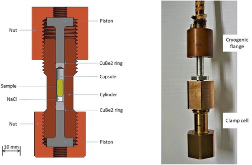
The sample with the maximum diameter of 4 mm and length of about 12 mm is placed in the capsules optionally made of Teflon (PTFE), the Al-Mg alloy (AlMg5, EN AW-5019) or lead. The AlMg5 material has a better mechanical stability than Teflon and lead. The thin-walled capsules, which have to be stable in shape, could be easily machined from this Al-Mg alloy using conventional tools. The sealing of the capsules is ensured with two CuBe2 extrusion rings. The relatively long unthreaded part of the cylinder allows for the use of an internal single-crystalline NaCl standard [Citation18] for the in situ pressure calibration (). The cell is attached to the sample rods of the cryostats and cryo-magnets using M8 threaded holes in both nuts ().
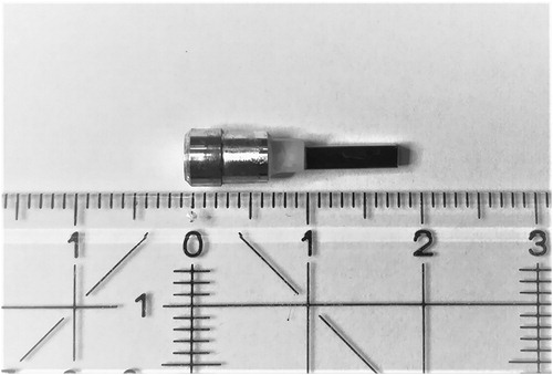
Figure 2. Single crystal of MnSi (1.8 × 2.0 × 8.0 mm³) mounted on the single crystal of NaCl (3.0 × 3.0 × 3.0 mm³) and the AlMg5 capsule plug.
The pressure calibration of the cell prototype, whose cylinder was made of CuBe2, based on the change of the NaCl lattice parameter [Citation18] was carried out on the beamline POLI. The AlMg5 capsule was filled with the 1:1 mixture of Fluorinert FC770 and FC75. The load was generated under a standard laboratory hydraulic press. The diffraction measurements were performed inside the 8 T magnet at two short wavelengths λ = 1.15 Å and λ = 0.90 Å with and without the cell for background estimation. The total vertical angular aperture of the 8 T magnet, designed specifically for the single-crystal diffraction, is 30° (−5°/+25°). In the combination with short neutron wavelengths and a lifting single-counter detector, it is possible to collect the data from several scattering planes (the exact number depending on crystal symmetry, lattice parameters and crystal orientation). Typically, a few hundred reflections can be collected using just one sample fixation [Citation19]. In the current experiment, all available reflections from the NaCl single crystal within the angular limitation were measured with 10 s per counting point at all pressures (the total number of reflections: 143). The overall time for the complete data collection was about 10 h. Detailed profile analysis and subsequent integration of the measured peaks revealed that among them 31 reflections could be observed above the 2σ limit and 21 reflections above the 3σ limit. From the latter ones, the 12 strongest peaks were used for the refinement of the orientation matrix and lattice parameters at different pressures and temperatures. An attempt to use all observed peaks in the refinement of the lattice parameters did not lead to a substantial improvement of the refinement quality. The results on the NaCl sample (3.0 × 3.0 × 3.0 mm³) show that (1) our setup could be reliably used for the mapping of phase diagrams following changes of selected relevant reflections and that (2) full structural data for the absolute structure refinements using a sufficiently big sample and an extended measurement time of a few days are possible at POLI. In addition, powder diffraction patterns can be collected at various pressures and temperatures.
As seen from the curve in , the CuBe2 prototype could be used to Pmax = 1.1 GPa. The limit pressure Pmax of elastic deformation of the cell is derived from the linear part of the curve [Citation7]. This demonstrates that the cell is stable up to the compression limit strictly determined by the mechanical properties of the CuBe2 cylinder (σ = 1.1 GPa) [Citation2,Citation7,Citation8]. It is worth mentioning that Pmax of other cells whose cylinders are made of CuBe2 (also for smaller sample volumes) is 1.1 GPa or lower [Citation2,Citation7]. Since NiCrAl used for pistons has much higher yield strength, it always remains in the elastic regime in our CuBe2 cell. It means that the clamp cell with this design is operational in the pressure range that entirely depends on the material used for its construction. The typical change of the length of the AlMg5 capsule compressed to 1.1 GPa in the CuBe2 cell is about 15%. The capsules and extrusion rings are single-use only. The cells made of both CuBe2 and NiCrAl can be cooled down to the base temperature of 3.8 K in the top-loading CCR cryostat in less than 3 h.
Figure 3. Pressure calibration of the CuBe2 cell with the single-crystalline NaCl internal standard at room temperature.

The CuBe2 cell prototype was tested regarding its transmission and its background at various points in reciprocal space to evaluate feasibility of inelastic neutron scattering studies with thermal and cold neutrons on the helimagnetic phase of MnSi under hydrostatic pressure on the beamline MIRA.
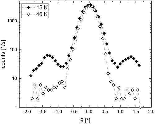
The crystal of MnSi () was oriented with the (110) and (111) reflections in the scattering plane. It was mounted together with the NaCl pressure standard and the cell was filled with the 1:1 mixture of Fluorinert FC770 and FC75. shows a comparison of the scans around the (110) Bragg reflection at 15 and 40 K (λ = 4.05 Å) below and above the magnetic phase transition temperature of 29.5 K. Due to the small ordered moment (0.4 μB/Mn) and large magnetic helix pitch of about 180 Å, the intensity of the magnetic satellites in MnSi is rather low compared to the main Bragg reflections. However, the two magnetic satellites with the propagation vector k = (0.015, 0.015, 0.015) are clearly visible in the helimagnetic phase, demonstrating that the beam attenuation and background are sufficiently low in order to enable detection of such magnetic contributions and to follow their evolution under applied pressure and magnetic field.
Figure 4. Scans on the (110) Bragg reflection of MnSi inside the cell at 15 and 40 K. The dashed lines are guides for the eye.
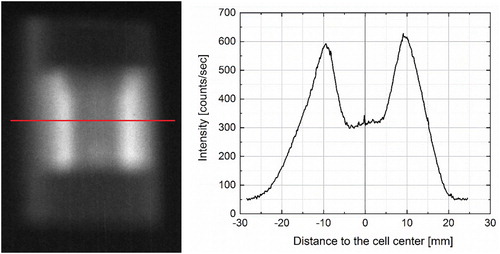
The transmission of the CuBe2 cell at room temperature was determined from the maximum neutron count ratio of the (110) Bragg reflection of MnSi determined in the rocking scans inside and outside of the cell on MIRA (). This ratio is 47% in agreement with theoretical estimations of Ttheo = 49.9% (). A similar transmission is expected also for DNS, a cold-neutron polarized instrument, while it should reach about 80% at the wavelengths close to 1 Å on POLI. Another way to determine the transmission could also be to measure the attenuation of the direct neutron beam passing through the cell by a scintillation camera. Such a transmission of the cell loaded with the NaCl standard and pressure medium on POLI (λ = 1.15 Å) reaches about 50% when the background due to the electronic noise in the camera is subtracted (), while it is about 64% without any background correction. However, this method clearly underestimates the actual transmission determined from the diffracted intensities () and theoretical predictions ().
Figure 5. Rocking scans of the (110) Bragg reflection of MnSi inside (closed symbols) and outside (open symbols) the cell measured at room temperature on MIRA (λ = 4.05 Å). The lines are the Gaussian fits to the data. The x axis values indicate the difference from the nominal position of the (110) Bragg reflection.
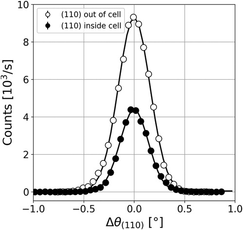
Figure 6. Neutron transmission calculated for the cell cylinders made of CuBe2 and NiCrAl at different wavelengths for the material thickness of 10 mm [Citation20]. The calculation does not include the attenuation effects from the capsule and pressure medium as well as from resonant and inelastic scattering.
![Figure 6. Neutron transmission calculated for the cell cylinders made of CuBe2 and NiCrAl at different wavelengths for the material thickness of 10 mm [Citation20]. The calculation does not include the attenuation effects from the capsule and pressure medium as well as from resonant and inelastic scattering.](/cms/asset/b808b34e-6d72-43e3-97d6-e709df187096/ghpr_a_1841759_f0006_ob.jpg)
Figure 7. Neutron transmission of the loaded CuBe2 cell at POLI – (left) The cell image recorded by the neutron scintillation camera. The red line indicates the sample position and the path of the neutron beam; (right) neutron intensity along the red line shown on the left. The transmission is defined as the ratio between the mean intensity in the centre of the cell and the one at the edge (the distance to the cell centre of about 8 mm) with subtracted background.
As already indicated earlier [Citation3], the Ni-Cr-Al alloy transmits fewer neutrons than CuBe2 ().
3. Conclusions
We have constructed and tested compact and non-magnetic clamp cells that fit into the existing low-temperature sample environment devices and are well adapted to multi-parameter (pressure/temperature/magnetic field) neutron scattering studies on both diffraction (POLI) and spectroscopy (DNS, MIRA) beamlines at MLZ. A good agreement between the design parameters and cell performance under the real experimental conditions could be proved. The new pressure cells can accommodate samples with volumes up to about 150 mm3 at pressures to above 1 GPa. They will be routinely available both to the in-house research and to the wide external MLZ user community. Given their relatively high transmission, they will enable high pressure polarized and inelastic neutron scattering experiments both at MIRA and DNS. A further development of clamp cells for 3He and dilution inserts as well as of fretted cells is also planned.
The single-crystal diffraction measurements were performed on the beamline POLI operated jointly by RWTH Aachen (Institute of Crystallography) and Forschungszentrum Jülich GmbH (JCNS) within the JARA cooperation. This work was supported by the project 05K19PA2 from the Bundesministerium für Bildung und Forschung (BMBF) and the project GE971/5-2 from the Deutsche Forschungsgemeinschaft (DFG).
Disclosure statement
No potential conflict of interest was reported by the author(s).
Additional information
Funding
References
- Scheerer GW, Ren Z, Watanabe S, et al. The dominant role of critical valence fluctuation on high Tc superconductivity in heavy fermions. npj Quant Mater. 2018;3:41.
- Klotz S. Techniques in high pressure neutron scattering. Boca Raton (FL): CRC Press/Taylor and Francis; 2013.
- Cheng Y, Brenk J, Friedrich B, et al. Ni–Cr–Al alloy for neuron scattering at high pressures. Mater Sci Tech. 2020;36(9):949–954.
- Sadykov R, Pappas C, Banneberg LJ, et al. 1.5 GPa compact double-wall clamp cell for SANS and NSE studies at low temperatures and high magnetic fields. J Neutr Res. 2018;20:25–33.
- Bowen DH, Jones GO. Superconductivity of tin, lead and thallium up to 10000 atmospheres. Proc Roy Soc. 1960;254A:522–536.
- Diederichs J, Gangopadhyay AK, Schilling JS. Pressure dependence of the electronic density of states and Tc in superconducting Rb3C60. Phys Rev B. 1996;54:R9662.
- Kamarád J, Machátová Z, Arnold Z. High pressure cells for magnetic measurements – destruction and functional tests. Rev Sci Instr. 2004;75:5022.
- Eremets MI. High pressure experimental methods. Oxford: Oxford University Press; 1996.
- Su Y, Nemkovskiy K, Demirdiş S. Heinz Maier-Leibnitz Zentrum. (2015). DNS: diffuse scattering neutron time-of-flight spectrometer. J Large-Scale Res Facil. 2015;1:A27.
- Georgii R, Seemann K. Heinz Maier-Leibnitz Zentrum. (2015). MIRA: dual wavelength band instrument. J Large-Scale Res Facil. 2015;1:A3.
- Georgii R, Weber T, Brandl G. The multi-purpose three-axis spectrometer (TAS) MIRA at FRM II. Nucl Instrum Methods Phys Res. 2018;A881:60–64.
- Hutanu V. Heinz Maier-Leibnitz Zentrum. (2015). POLI: polarized hot neutron diffractometer. J Large-Scale Res Facil. 2015;1:A16.
- Hutanu V, Meven M, Heger G. Construction of the new polarised hot neutrons single-crystal diffractometer POLI-HEiDi at FRM-II. Physica B. 2007;397:135–137.
- Mühlbauer S, Binz B, Jonietz F, et al. Skyrmion lattice in a chiral magnet. Science. 2009;313(5916):915–919.
- Georgii R, Weber T. The helical magnet MnSi: Skyrmions and Magnons. Quantum Beam Sci. 2019;3(1):4.
- Ritz R, Halder M, Wagner M, et al. Formation of a topological non-Fermi liquid in MnSi. Nature. 2013;497(7448):231–234.
- Pfleiderer C, Reznik D, Pintschovius L, et al. Partial order in the non-Fermi-liquid phase of MnSi. Nature. 2004;427(6971):227–231.
- Skelton EF, Webb AW, Qadri SB, et al. Energy-dispersive x-ray diffraction with synchrotron radiation at cryogenic temperatures. Rev Sci Instrum. 1984;55(6):849–855.
- Hutanu V, Deng H, Ran S, et al. Low-temperature crystal structure of the unconventional spin-triplet superconductor UTe2 from single-crystal neutron diffraction. Acta Cryst B. 2020;76:137–143.
- https://www.ncnr.nist.gov/resources/activation/