
 ?Mathematical formulae have been encoded as MathML and are displayed in this HTML version using MathJax in order to improve their display. Uncheck the box to turn MathJax off. This feature requires Javascript. Click on a formula to zoom.
Abstract
Based on the MGT positioning method, the performance of combined magnetic beacon is studied. The unit size of beacon is designed as D = 2 cm and L = 8 cm, the performance of different structure magnetic beacons combined have been studied and compared in detail, results show that the magnetic field intensity of cross structure is about 30000nT higher than the orthogonal structure which have generated sine waves. According to the TLS to filter the signal based on the regular tetrahedral gradient tensor measurement array. In the laboratory environment (Bearth=46157nT) to validate the model in this paper, the experimental results show that the array of two identical cross-combined permanent magnets will increase the magnetic induction value at the same distance by 1.7 times and the max-average positioning error on the 6 experimental paths is 1.52m. The implications of these findings particularly regarding the array rotation combined magnetic beacon may be useful for the high-precision magnetic position systems.
1. Introduction
Generally speaking, the magnetic field signal is greatly affected by ferromagnetic objects, but it is less sensitive to the direct effects of weather conditions and daily changes, so the modern magnetic positioning systems are increasingly used in medical and drilling fields, but the accuracy of long-distance positioning is poor because of the fast attenuation of magnetic signals [Citation1–3]. For example, in the drilling field, single and static magnetic beacons are commonly used for positioning, the positioning accuracy is mainly dependent on the magnetic field strength but under the influence of the environmental magnetic field (Such as the geomagnetic field), signals generated by beacon is easily overwhelmed, resulting in limited positioning distance [Citation4]. In the medical field, multiple-element arrays beacons are used to locate the magnetic sensor installed in the diagnostic capsule with high positioning accuracy, but the action scope is limited [Citation5–9].
The published literature contains a vast number of papers on the static magnetic position. However, to extract the signal generated by the beacon from the Environmental Magnetic Field (EMF), the initial value of the EMF must be measured firstly, which will reduce the real-time nature of the system and may bring a secondary error. Work by Arie Sheinker (2016) carried out a series of research on rotating magnetic beacon positioning methods [Citation10] corresponding to two beacons which can realize the diagonal positioning and is not necessary to know the precise magnetic moment value of each beacon. In a relatively long-distance, the positioning accuracy is well, but it is easy to cause error when the beacons are not in the same plane. Other closely related work (Deng et al. Citation2017, Asieh Soheilian et al. 2020) [Citation5, Citation11–14] according to the geometric characteristics of magnetic, they converted the value measured by the magnetic dipole into the receiver position estimate, which have provided more ideas for improving the magnetic position and direction tracking accuracy. However, these methods still have some deficiencies in that (1) easily affected by partial metal objects and environmental magnetic fields. In addition, (2) the environmental magnetic field in which the magnetic beacon is located needs to be measured in advance with high accuracy. Moreover, (3) the scope of action is limited [Citation15] by the transmission distance of the magnetic signal and cannot be used remote. In our problem scenario, array beacons can theoretically extend the positioning range to any distance. The dynamic magnetic field generated by the rotating beacon can filter most environmental magnetic field [Citation16] during the calculation process to achieve the long-distance and high-precision positioning.
In order to improve the problem of limited transmission distance of single beacon magnetic signal, this paper derived the calculation formula of the spatial magnetic dipole in detail, and proposed three kinds of combined beacons, namely orthogonal combination, cross combination and cone combination which are suitable for different occasions. In order to reduce the fixed error generated by the magnetometer, a regular tetrahedron measurement array is used to detect the magnetic field signal at the receiving, without measuring the characteristics of the ambient magnetic field; the TLS is used to extract the sinusoidal signal. Processing the obtained dynamic magnetic field data to calculate the MGT to obtain the relative position of the beacon and the sensor, This method retains the advantages of using magnetic beacon positioning [Citation17], at the same time, it does not need to compensate for the earth’s magnetic field, and the array magnetic beacon can effectively expand the navigation provides ideas for the application of magnetic navigation positioning systems in special fields such as underwater and underground.
2. Design of magnetic beacon structure
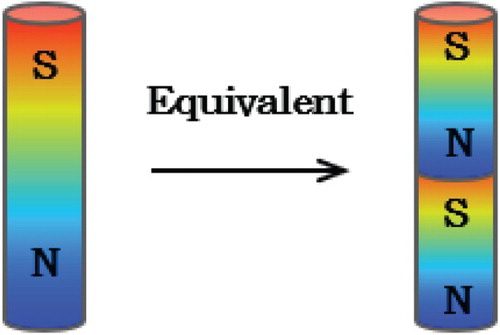
Taking into the requirements for the uniformity and stability of the signal in the magnetic positioning system, we selected a cylindrical magnet beacon as the source structure. When the permanent magnet is uniformly magnetized in the axial direction, the demagnetizing field of the beacon becomes stronger as the dimension factors k = L/D increases resulting in the magnetic signal will decay faster, but too small will weaken the beacon’s mechanical strength and shrink the service life [Citation18]. When the magnet length exceeds 10 cm, the beacon is difficult to press and the mechanical strength is low, and when it reaches 25 cm, it is expensive and not suitable for general use [Citation19]. When the magnetization directions of the permanent magnets are the same, a small-volume magnet unit can be combined shown in Figure , and the magnetic field generated by any volume of the magnet after the combination is almost equal to the magnetic field generated by a magnet of the same size. Therefore, the optimal volume size of the beacon can be obtained by combining a plurality of small volume magnet units.
Figure 1. Schematic diagram of equivalent structure of permanent magnet beacon.
The magnetic induction strength and current density of a permanent magnet satisfy:
(1)
(1) The vacuum permeability
,
is the magnetization of the beacon. When the cylindrical permanent magnet is located at the coordinate origin and is uniformly magnetized in the axial direction, the magnetic field generated at any point
in space can be expressed as:
(2)
(2) Where
is the residual magnetic field strength of the magnet,
and
are the length and radius of the magnet, and the total magnetic field strength can be calculated as:
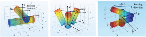
Among them, the design structure and rotation direction of three types of combined magnetic beacons are shown in Figure . The two magnets of the orthogonal combined are arranged in the axial direction, one magnet is axially along the X-axis direction, and the other is along the Y-direction. The conical combined magnetic beacon contains three magnets with magnetization directions along their respective axis directions. The apex inverted tetrahedron at the origin of the coordinates and the axis direction of each magnet differs by 120° in the XOY plane, and the angle with the XOY plane is θ, before comparing the performances of the three types of magnetic beacons, the influence of the θ on the beacon performance needs to be discussed. The cross combined beacon crosses the magnetization direction in the XOY plane, and the cross angle needs to be studied too. The three combined beacons rotate in the counter clockwise direction along the Z axis.
Figure 2. Schematic diagram of three combined beacons. (a) Orthogonal combined beacon structure; (b) Conical combined beacon structure; (c) Planar cross-combined beacon structure.
The magnetic field distribution of the combined beacons is discussed below. The magnetic beacons are still set to be cylindrical magnets of diameter D = 2 cm and length L = 8 cm, the influence of θ on the magnetic field intensity and distribution of the magnetic beacon studied by the conical combined beacon, the model was simulated by Comsol Multiphysics and the rotation frequency of the conical combined beacon in vacuum was set f = 10 Hz. Taking a representative data of one-point in space shown in Figure .
Figure 3. Field strength simulation of cone beacon.
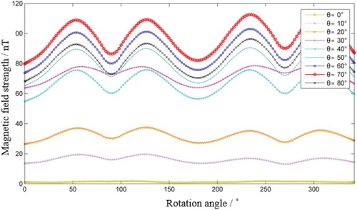
It can be seen from the simulation results that the signal strength generated by the cone combined beacon is nonlinearly proportional to the θ angle. When θ = 70°, the signal amplitude of the magnetic field signal is strong and the features are obvious, which is more conducive to feature extraction. Therefore, conical magnetic beacons can be used as a signal source for positioning systems. Considering the principles of magnets repulsing in the same direction and attracting in opposite directions, in order to make the magnetic field more evenly and symmetrically distributed in space, the three magnets of the plane cross combination beacon are designed to follow the same magnetization direction at XOY and intersect 60° with each other. The signals generated by the three types of magnetic beacons rotating in a vacuum environment at θ = 45° and r = 10 m were simulated and the results shown in Figure .
Figure 4. Signal waveform diagram generated by rotating beacons.
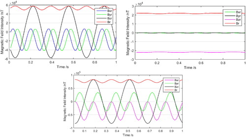
By analyzing the simulation results in Figure , we can know that: (1) when the shape and volume of the magnet are the same, as the number of magnets increases, the signal strength changes nonlinearly. (2) The three components and the total magnetic strength generated by the orthogonal beacon and the cross beacon during rotation are sine waves, and the cross combined beacon is about 30,000 nT higher than the orthogonal combined beacon. (3) The characteristic frequency resolution of the magnetic signal generated by the cone combined beacon during rotation is small and difficult to detect, but the magnetic field in the Z axis direction is higher than other beacons, although the signal strength at one point in space is lower than the other types of combined beacons, but with higher directivity, it is suitable for static magnetic positioning systems. According to the localization method in this paper, the cross combined beacon is selected as the signal source for research.
3. Coupled signal extraction
The magnetic signal is the key to the position system [Citation20]. In practice, signals received by the fluxgate magnetometer include signals generated by magnetic beacons , all inherent errors
, soft magnetic interference and the resulting change in magnetic field error
, the total magnetic strength
received can be expressed as:
Where
is the soft magnetic induction coefficient of the background magnetic field and as a symmetric matrix, each component is a known constant. For the magnetic field generated by the rotating beacon is a standard sine wave magnetic field, the signals generated by non-beacons can be regarded as noise, that is
, the formula (2) can be simplified as:
(3)
(3) Among them,
is the total signal produced by the magnetic beacon and the environmental noise,
is the direction,
as the inherent deviation of the signal receiving system is a known quantity, and
,
,
are the frequency and amplitude and phase of the magnetic signal,
is the noise signal, and the signal frequency is determined by the rotation frequency of the beacon which is a known value. Linearizing the magnitude of the total magnetic strength could get as follow:
(4)
(4) Among them,
,
,
, the sampling value obtained at the moment
by the induction magnetic signal
of the receiving is:
(5)
(5)
Therefore, the error function of the system can be defined as:
(6)
(6) Where
is the total number of extracted signals, and where
(
) is the time when the magnetic signal is received. In practice, a certain frequency offset occurs during the transmission of the signal. To ensure the accuracy of the extraction, the actual frequency
of each signal needs to be found. Set the highest and lowest limits of the frequency as
of the signal
to make the frequency satisfy
. Determine the iteration step of each signal frequency as
and the number of iterations is
. To find the minimum error function
, use the TLS to solve the appropriate values of
,
and
.
(7)
(7)
(8)
(8)
(9)
(9)
The TLS of the system error function is , and then the values of
,
and
are solved, and the frequency
of each signal is cyclically iterated in order to find the frequency which can minimize the error function, and the amplitude and phase calculate as:
(10)
(10)
So that the signal at the receiving end is:
(11)
(11) To ensure the accuracy of the results, it is possible to iterate multiple times with as many sampling points as possible to extract the sinusoidal signal required by the positioning system from the ambient noise.
4. Positioning mechanism of magnetic field gradient tensor
4.1. Magnetic field gradient tensor
MGT contains a large amount of magnetic field information [Citation21], the measurement of it can reflect the vector information of the magnetic field and describe the magnetic signals well without special treatment [Citation22]. In the Cartesian Coordinate System, the change rate of components of magnetic induction in different directions constitutes a second-order tensor denoted as G as follows:
(12)
(12) Since the baseline length between magnetometers is much shorter than the distance from the magnetic source to the measurement point, the differential method is used to calculate the MGT actually. According to the principle of magnetic connectivity, both the divergence and the rotation of the static magnetic field are 0 [Citation23].
(13)
(13) According to the beacon structure proposed in this paper, it produces a time-varying magnetic field signal B(t), At this time, it is necessary to measure and calculate each variable in MGT through research, so this paper uses the regular tetrahedral tensor measurement model to solve this problem.
4.2. Magnetic gradient tensor positioning model
Assuming the position of the magnetic source is and the coordinates of the measuring point is
, the basic expression of Euler deconvolution is:
(14)
(14) Where B is the magnetic induction intensity function of the magnetic source, where M is the background magnetic field, and where N is the tectonic index which is related to the geometry of the field source and indicates the field decays with distance. In general, the magnetic field strength of the background changes relatively slowly with distance, so the first derivative value is relatively small, and the first derivative of the artificial magnetic source can be ignored [Citation24, Citation25]. The structural index of the magnetic field source is 3, so take the first derivative of every directions in (12) to eliminate the background magnetic field M can get the following formula:
(15)
(15)
So that when the magnetic beacon is located at the coordinate origin , the position of the measured point is:
(16)
(16) Therefore, by measuring the three-component and MGT of a magnetic dipole at a certain measuring point, the position coordinates of the measuring point relative to the magnetic dipole can be calculated, at the same time, the values of roll angle and pitch angle are derived.
5. Experiment and analysis
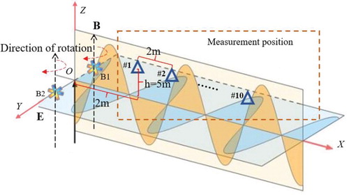
5.1. Rotating magnetic beacon layout and signal measurement array
The unit structure of a single permanent magnet is diameter D = 10 cm and long L = 50 cm. The surface of the magnet is wrapped with a plastic film with a thickness of 1 mm. The remanence of the magnetic beacon is 1.5 T, the size factor is 5, the demagnetization factor is 0.14, the magnet volume is 1250cm3, the basic structure of the rotating magnetic beacon is the cross combined beacon and Figure is the layout schematic diagram of the two types of beacons.
Figure 5. Schematic diagram of beacon location. (a) Unary beacon. (b) Binary beacon.
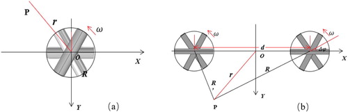
The beacon whirl along the Z axial counter clockwise direction, and the rotation frequency is . Similarly, the distance between the binary array beacons is d, and the difference between the initial rotation angles of the two beacons is
, when the field strength at point P is measured at the distance r, and the origin position is the midpoint of the two beacons.
Through the analysis, the tetrahedral array measurement system is used to verify the proposed positioning method [Citation26]. The gradient tensor system mounted on the target includes four vector magnetometers located at the apex of the tetrahedron. As shown in Figure , The core point of the tetrahedron is the core of the circumscribed sphere.
Figure 6. Tetrahedral gradient tensor measurement system.
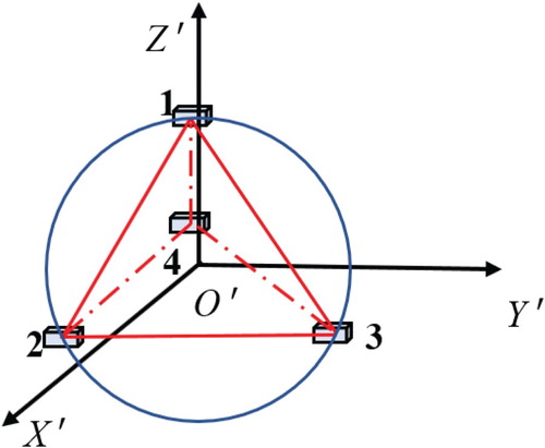
The magnetic field of each magnetometer is , according to the component of the gradient tensor of the difference equation:
(17)
(17) Among them,
,
and
is the difference between magnetometer No.1 and No. k, and
is the displacement difference witch is a known value.
(18)
(18)
(19)
(19) Eliminate the singular values and take the average of the maximum values in each signal period to obtain the MGT and field strength at the core of the measurement array, which can be expressed as Equations (16) and (17).
(20)
(20)
(21)
(21) The position information of the target can be obtained by bringing the above measurement values into Equation (16).
5.2. Experiment and result analysis
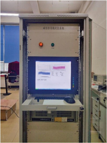
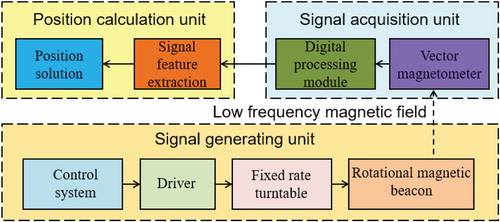
In the laboratory environment, with magnetic beacons as the core to built an experimental platform for the target positioning system which is mainly composed of the following parts: magnetic beacon, turntable, three-axis magnetometer sensor, AC and DC power supply, signal acquisition and data processing software, etc. The data acquisition system is shown in Figure .
Figure 7. Magnetic field data acquisition system.
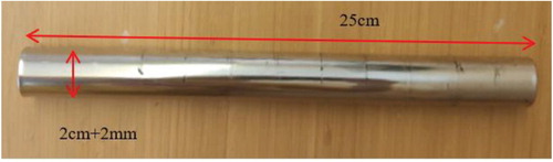
Select NdFeB series permanent magnet as the beacon material, the relevant parameters are shown in Table and a single magnet is shown in Figure . Among them, the surface of the NdFeB magnet is 12,000 Gauss, the operating temperature is 80°, the turntable energization voltage is 30 V, the rotation frequency is 20 Hz, and the standard fastener is H62 brass.
Table 1. The main parameters of the two kinds of NDFeB.
Figure 8. Schematic diagram of a single magnet.
Through comparative analysis, the sintered NdFeB permanent magnet with grade N55 is used as the raw material of the magnetic beacon and the error of the positioning result is defined as:
(22)
(22) Among them,
is the true value and
is the calculated value of the target position. According to the actual define the value of arrays and the rotation frequency of the beacon is
, d = 5 m,
. In the coordinate of the measurement array, using the position of the magnetic beacon as the coordinate origin. In order to facilitate the positioning of the magnetic sensor, the height of the sensor is defined as 5 m, and vertical coordinates is 0 as Figure .
Figure 9. Magnetic beacons and measurement location.
After determining the position of the coordinate origin, to accurately measure the precise position of each measuring point and record it by tape, and then measure the signal data of the magnetometer at each measuring point, repeat the experiment and check the collected data which mainly includes the collection time, total magnetic field, X-axis component, Y-axis component, Z-axis component, etc. Import the checked data into MATLAB software for position calculate, the experimental process is shown in Figure .
Figure 10. The experimental process.
As shown in Figure , multiple experiments were performed at each location to obtain data of sensor No.1, where Bx, By, and Bz are the three components of the magnetic field. Signal measurement waveforms at three positions which are #1, #5, and #10.
Figure 11. Magnetic field signal of sensor 1 at #1, #5 and #10.
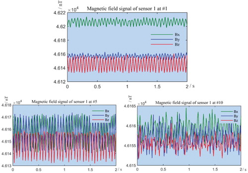
The results show that as the distance increases, the signal strength decreases and the characteristics of the signal gradually weaken, which can be clearly seen at position #1, but at position #10 the signal is basically in a distorted state. Consider the mirror symmetry of the magnetic field, perform position calculation on the six paths shown in Figure and the positioning errors are shown in Figure .
Figure 12. Schematic diagram of six positioning paths.
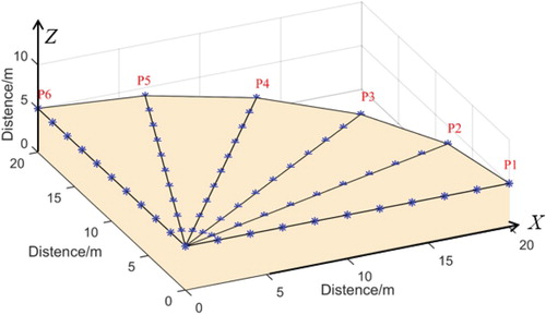
The positioning error of each path is shown in Figure , where figure (a) (b) (c) are the errors in the X-axis direction, Y-axis direction and Z-axis direction, and define the max-average positioning error as .
(23)
(23) Among them,
means the average error of 10 measuring points on each path, and
.
Figure 13. Positioning errors caused by different paths in three axes. (a) The errors in the X-axis direction. (b) The errors in the Y-axis direction. (c) The errors in the Z-axis direction.
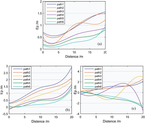
The results show that the lateral max-error is 1.58 m, the longitudinal max-error is 2.86 m, the vertical max-error is 3.47 m and the max-average positioning error is 1.52 m. Among them, the error generated in the Z-axis direction is the main source of error, which because the baseline length of the Signal Receiving System is restricted in this direction and leads to the deviation of the MGT calculation. In addition, the error in the X-axis and the Y-axis direction changes regularly with paths, because the beacon cannot be fully synchronized during the rotation process, but this does not change the effect of positioning at each location. The error sources of the comprehensive analysis system mainly include the following aspects: (1) the coordinates of magnetic beacon and target carrier are not completely coincident. (2) the measurement accuracy of magnetometer sensor is not high. (3) some disturbances which are difficult to model such as measurement noise and system noise and the surrounding environment (Temperature, Humidity, etc.) will also affect the performance of each measurement.
6. Conclusions
Aiming at the problem of short range and low robustness of magnetic beacon positioning system, (1) this paper puts forward three combined structures of orthogonal, cone and crossing by the cylindrical based on the analysis magnetic field of permanent magnet and obtains the magnetic field characteristics of rotating beacon in space. (2)Through finite element analysis, we found the three components of magnetic field of orthogonal and cross combined beacon is sine wave magnetic field, and the magnetic field stability is good. The field of cone combined beacon has good directivity, which is more suitable for the static magnetic positioning system with invariant characteristics. (3) This paper improved the positioning distance and robustness well, at the same time, there is no need to measure the size of the environmental magnetic field in advance, which greatly improves the real-time performance of the system, so that if conditions permit, multiple arrays can be used as a signal source. Further analysis the factors that affect the positioning error, the distance and asynchronous rotation of the beacons in actual work will lead to low positioning accuracy results.
Disclosure statement
No potential conflict of interest was reported by the author(s).
Additional information
Funding
Notes on contributors
Hua Guan
Professor Guan Hua is the vice president of information and navigation College of Air Force Engineering University. He has been engaged in the research of geomagnetic navigation and positioning technology for a long time, and has unique views and research methods on magnetic beacon positioning technology.
References
- Sun H, Yang BF, Li C, et al. Compensation method for double estimation of geomagnetic sensors in geomagnetic navigation. J Detect Control. 2019;41(5):90–95.
- Luo JP, Chen MY, Li JP, et al. An indoor autonomous guided vehicle based on electromagnetic tracking and positioning ibeacon. Proceedings of the 30th China Conference on Control and Decision (5). Liaoning: IEEE; 2018. p. 1225–1230.
- Zhou YH, Kou BQ, Liu P, et al. Force characteristic analysis of a magnetic gravity compensator with annular magnet array for magnetic levitation positioning system. Aip Adv. 2018;8(5):056706.
- Jia WD, Lin CS, Sun YH, et al. Research on magnetic target location method based on a single magnetic gradiometer. Bing Gong Xue Bao Acta Armam. 2017;38(8):1572–1577.
- Deng GQ, Yao AG, Gong Z, et al. Real-time positioning method of horizontal directional drilling based on ground magnetic beacons. Earth Sci. 2017;42(12):2336–2344.
- Liu CY, Wang G, Xia HG, et al. Magnetic beacon autonomous positioning method based on firefly algorithm. Navig Position Timing. 2018;05:65–70.
- Luo ZY, Guo XD, Qin RH, et al. Digital design of electronic capsule frequency division excitation localization device. Int J Biomed Eng. 2018;;41(5):423–427.
- Li CF, Li GQ, Liu HQ, et al. A novel gold nanoparticles decorated magnetic microbead-based molecular beacon for DNA multiplexing detection by flow cytometry. Anal Chim Acta. 2020;1110:19–25.
- Zhong YC, Yi F, Xie XX, et al. Molecular beacon-based fluorescence magnetic nanoprobes for tumor-related HSP90 mRNA in-suit detection and imaging. Fed Am Soc Exp Biol. 2019;33:S1.
- Sheinker A, Ginzburg B, Salomonski N, et al. A method for indoor navigation based on magnetic beacons using smartphones and tablets. Measurement. 2016;81:197–209.
- Davis CP, Chew WC, Tucker WW, et al. A null-field method for estimating underground position. Transact Geosci Remote Sens. 2008;46(11):3731–3738.
- Paperno E, Sasada I, Leonovich E. A new method for magnetic position and orientation tracking. Transact Magn. 2001;37(4):1938–1940.
- Li QH, Zheng YX, Yuan LIU, et al. A positioning and orientation method based on double magnetic beacons. Proceedings of 2016 China International Conference on Inertial Technology and Navigation; 2016. p. 533–537.
- Zhang SM, Meng X. Use of an inertial/magnetic sensor module for pedestrian tracking during normal walking. IEEE Trans Instrum Meas. 2015;64(3):776–783.
- Zheng LF, Wan Y, Guan SY, et al. A method for expanding the workspace of electromagnetic positioning system. J Beijing Univ Aeronaut Astronaut. 2019;45(10):1956–1964.
- Tu B, Li DS, Lin EH, et al. Rotating magnetic beacons magnetic field strength size in SAGD. Front Mech Eng Chin. 2010;5(4):446–449.
- Zhang DC. Research on positioning method based on magnetic beacons and error analysis. Harbin: Harbin Institute of Technology; 2016.
- Chang S, Fu XM, Zhang CC, et al. Underwater SLAM method based on magnetic beacons. J Underwater Unmanned Syst. 2019;27(3):277–283.
- Pourarian F. Development of high performance permanent magnets based on Nd-Fe-B system. Magn Superconduct Mat. 2000;2:975–990.
- Kurniawan C, Nainggolan MM, Sebayang K, et al. Preparation and characterization of Fe-Mn-doped barium hexaferrite permanent magnet. J Phys Conf Ser. 2017;817(1):012057.
- Zhang QW. Research on magnetic measurement and positioning technology of connected wells. Guangdong: Guangdong University of Technology; 2015.
- Pedersen LB, Rasmussen TM. The gradient tensor of potential field anomalies: some implications on data collection and data processing of maps. Geophysics. 1990;55(12):558–1566.
- Wang SS, Zhang MJ, Zhang N, et al. Calculation and correction of magnetic object positioning error caused by magnetic field gradient tensor measurement. Syst Eng Elect Technol. 2018;29(3):16–21.
- Ni FQ. Mathematical methods of electromagnetic field theory. Teach China Univ;6:29.
- Pasku V, Angelis AD, Angelis GD, et al. Magnetic field-based positioning systems. IEEE Commun Surv Tutor. 2017;19(3):2003–2017.
- Fan XT, He J, Liu YX. Development of magnetic field spatial distribution measurement technology. Navig Contr. 2020;19(1):97–104.