
 ?Mathematical formulae have been encoded as MathML and are displayed in this HTML version using MathJax in order to improve their display. Uncheck the box to turn MathJax off. This feature requires Javascript. Click on a formula to zoom.
Abstract
For ultrasonic welding of carbon fiber-reinforced plastics (CFRPs), a sharp shaped resin called the energy director (ED), is usually inserted between them. In this study, finite element analyses for ultrasonic welding of CFRPs were performed using a two-dimensional model. The effects of the shape of the ED on the temperature increase, deformation history, and dissipated energy behaviors are discussed. Flat and triangular ED shapes are considered. From the results, it is easier for a triangular ED to increase the temperature than for a flat ED, and hence, the consumed energy and time are less for a triangular ED than for a flat ED. However, in the triangular ED, the temperature is distributed significantly, that is, there is a very high temperature at some point and a very low temperature at other points. Thus, unexpected chemical reactions, such as oxidation, may occur. This study concludes that a triangular ED is not always better than a flat ED. In any case, it was found that an abrupt temperature increase was caused by a synergistic effect. That is, the increase in temperature causes the viscoelastic and frictional dissipated energy to be remarkable, and the increase in the dissipated energy increases the temperature.
1. Introduction
Carbon fiber-reinforced plastics (CFRPs) are widely used in the aerospace industry because of their superior specific strength and stiffness. In the future, CFRPs are expected to be applied in a wide range of fields, including the automotive industry. To date, most CFRPs have been molded using thermosetting resin composites, but the use of thermoplastic composites instead of thermosetting resin composites is accelerating because of their moldability and productivity [Citation1–7]. Thermoplastic composites have advantages such as excellent impact resistance and recyclability [Citation8] as well as short processing time [Citation9]. In addition, given the characteristics of thermoplastic resins, it is possible to perform welded joints [Citation8], and joining components without bolts or rivets leads to reduced weight and stress concentration. Ultrasonic welding is a welding method [Citation5,Citation10,Citation11]. Ultrasonic welding uses the heat generated when transmitting vibration energy Appendix 1 to the welded interface to melt and weld the resin [Citation12]. Because thermoplastics can be welded quickly and efficiently, and with high energy efficiency, they are expected to be used in the future to join large components such as those of aircraft [Citation13–15]. In ultrasonic welding, it is common to melt by inserting a protrusion of resin at the interface [Citation1,Citation16–18]. This protrusion is called the energy director (ED) [Citation19–21]. As EDs are the starting point for melting, they enable highly reproducible welding when introduced in the interface.
Numerous studies have discussed EDs [Citation1,Citation14,Citation16,Citation19,Citation21–24]. Wang Tao et al. reported that when a flat ED is inserted in the interface, the extent of the unmelted area and the number of cracks are significantly reduced compared to the case without ED insertion [Citation12]. In addition, Levy et al. reported that the edge of the flat ED caused slippage at the weld interface and heat generation due to friction. In another paper, it was reported that when a triangular ED was introduced, stress concentration occurred at the tip, and the heat generation due to viscoelastic energy dissipation became dominant [Citation25]. Thus, it has been reported that the starting point of resin melting and welding time differ depending on the shape of the ED.
The purpose of this study is to develop a two-dimensional ultrasonic welding model and to discuss the effects of different ED shapes and pressing pressures on the temperature rise behavior of the ED. Two types of ED shapes, flat and triangular, were considered. The analysis was performed using the finite element method, and the ultrasonic vibration was expressed by repeatedly applying an oscillating stress to the top of the composite. In this analysis, the actual vibration frequency, which is approximately 20 kHz [Citation1,Citation16,Citation26–30], was set to 10 Hz to reduce the computational cost. To avoid the vibration energy being lower than the actual value, the specific heat and density of the ED were set lower than the actual values in this analysis to increase the amount of heat generated. For simplicity, the inelastic behavior of the resin was modeled as linear viscoelasticity without considering plasticity. The energy dissipation due to viscoelasticity refers to the energy lost without being stored when an external force is applied. We also introduced the Arrhenius-type time-temperature superposition principle into the viscoelastic behavior. In other words, as the temperature of the ED increased, the viscoelastic behavior became more pronounced and the dissipated energy increased, which led to a further increase in temperature. In the Results and Discussion section, we first compared the change in deformation over time for different ED geometries. Next, the heat generation and energy dissipation were calculated, and their rates were qualitatively discussed. Finally, the temperature distribution of the ED during heat generation was calculated, and the differences between the ED shapes were compared.
2. Analysis method
2.1 Finite element analysis
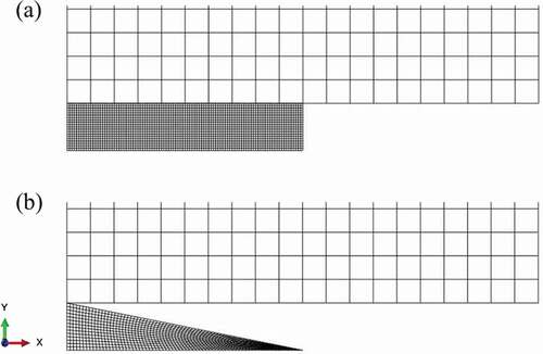
The two-dimensional ultrasonic welding model shown in was created. The general-purpose finite element analysis code ABAQUS 2018 was used in the numerical analysis. The composites were square in shape, and the length of one side was 1 mm. The EDs were rectangular (flat) and triangular. The mesh of the ED is shown in . The material properties set for the composite and ED are listed in [Citation25]. In this analysis, the properties of the CFRP were not considered to have a significant effect on the results, so isotropy was assumed, and a value of stiffness higher than that of the resin (the lateral stiffness of unidirectional CFRP) was used. Thermal stresses were not considered in the Appendix 1 model because they were not expected to affect the analytical results significantly. The oscillating stresses were set to 0.6 MPa and 4.5 MPa. Numerical simulation is difficult because of the large difference between the actual welding time (~10° s) and vibration frequency (~10−5 s). In this study, the specific heat and density were set lower than the actual values to increase the amount of heat generated by a single vibration, and the 10 Hz vibration simulated an ultrasonic vibration of approximately 20 kHz. An interfacial interaction property was introduced between the composite and ED, and the friction coefficient was set to 0.13.
Table 1. Material properties [Citation25]
Figure 1. Analysis model of thermoplastic polymer welding.
Figure 2. Mesh over the computation domain; (a) Flat ED, (b) Triangular ED.
2.2 Viscoelastic properties
In this study, the relaxation modulus was defined for the ED using EquationEquation (1)
(1)
(1) [Citation31]. Here, E(0) is the initial modulus,
is the relaxation time, and n is the power law.
In this study, the relationship between the elastic modulus and time is derived using EquationEquation (1)(1)
(1) with
and
[Citation32,Citation33]. The normalized curve shown in was created to determine the elastic modulus at a certain point in time.
Figure 3. Stress relaxation data.
We also assumed thermorheological simplicity, where the relaxation time is shorter at higher temperatures. In this case, the conversion time is given by EquationEquation (2)(2)
(2) .
Here, is called the shift function. When the temperature is changed from a reference temperature to any temperature
, all relaxation times become
times the value at
.
For the shift function, we used the Arrhenius rule expressed in EquationEquation (3)(3)
(3) .
is the activation energy, and
is the general gas constant. In this study, the activation energy was set to 150 kJ/mol [Citation25], and the reference temperature was set to −35 °C. This reference temperature was effective for showing qualitative differences in the results within the scope of this analysis. It should be noted that the reference temperature itself has no significant meaning.
2.3 Governing equation of heat generation
The energy dissipation rate owing to frictional sliding is defined by EquationEquation (4)(4)
(4) [Citation1].
where τ is the frictional stress and γ ̇ is the sliding velocity.
Furthermore, the amount of energy released to each surface as heat is given by EquationEquation (5)(5)
(5) .
where is the amount of energy converted to heat at the ED interface, and
is the amount of energy converted to heat at the composite interface.
is the fraction of the frictional energy converted into heat. In this study, f is the fraction distributed to each surface, which is assumed to be 0.5. The energy dissipation of viscoelasticity is then defined using EquationEquation (6)
(6)
(6) ,
where is the inelastic thermal conversion coefficient, which was set to 0.9.
is the stress, and
is the inelastic strain rate. There is no validity in this numerical setting, and thus this analysis does not deviate from the qualitative evaluation. Therefore, the total amount of energy converted as heat,
, is expressed as the sum of the energy dissipation due to frictional sliding and viscoelastic energy dissipation, as shown in EquationEquation (7)
(7)
(7) .
3. Analysis results and discussion
3.1 Transformation of the energy director
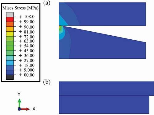
The time histories of the synthetic displacements when the model is subjected to stress are shown in . The left end (0.000 s) shows the scene before stress loading, and the deformation of the ED increases with time. First, we discuss the case where the model is subjected to a stress of 0.6 MPa. The deformation of the flat ED was extremely small compared to that of the triangular ED. Subsequently, both the flat and triangular EDs deformed when a stress of 4.5 MPa was applied. However, the triangular ED started
Appendix 1 to deform at the first stress loading, whereas the flat ED started to deform significantly at the tenth stress loading. This may be due to the stress concentration at the vertex in contact with the interface. shows the stress distributions of the flat and triangular EDs at 0.25 s when a stress of 0.6 MPa is applied. In the flat ED, the stress distribution is uniform, whereas in the triangular ED, stress concentration occurs at the vertex in contact with the interface. In other words, as shown in EquationEquation (6)(6)
(6) , the viscoelastic energy dissipation is proportional to the stress, and the stress concentration at the vertex makes the viscoelastic dissipation more pronounced and preferentially generates heat. The analytical results of this study support the experimental fact [Citation31] that a triangular ED can be welded with less vibration energy than a flat ED.
Figure 4. Relationships between displacement and time for; (a) Flat ED (0.6 MPa), (b) Triangular ED (0.6 MPa), (c) Flat ED (4.5 MPa), (d) Triangular ED (4.5 MPa).
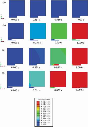
Figure 5. Stress distribution at 0.25 s; (a) Triangular ED (0.6MPa), (b) Flat ED (0.6MPa).
3.2 Temperature change of energy director
shows the temperature variation of the ED with time under a stress of 0.6 MPa. Here, temperature refers to the average temperature of the entire ED.
Figure 6. Temperature histories of the ED (0.6 MPa).
shows that the triangular ED showed a significant temperature increase at the third and tenth stress loading, whereas the flat ED did not. This result can be attributed to the energy dissipation. The energy dissipation due to viscoelasticity under the same loading conditions is shown in . The triangular ED shows a significant increase at the third and tenth stress loading, similar to the temperature change in . At the third loading, the temperature increases because it partially exceeds 80°C due to the stress concentration at the ED vertex, as shown in . Similarly, the large temperature change at the tenth load is considered to be due to the fact that the overall temperature exceeded 80°C. The temperature increase between the third and the tenth load is not large, which may be due to the deformation of the ED, which prevents Appendix 1 the stress from concentrating. The energy dissipation due to friction under the same loading conditions is shown in . Compared to the energy dissipation due to viscoelasticity, the energy dissipation due to friction is very small. These results indicate that the viscoelastic properties of the resin are the dominant factor in the temperature rise of the ED when a triangular ED with a pronounced stress concentration is used.
Figure 7. Temperature distribution near the apex of a triangular ED under a stress of 0.6 MPa. In the third loading, the stress was concentrated at the apex of the triangle ED and the temperature partially exceeded 80°C, resulting in a large temperature increase.
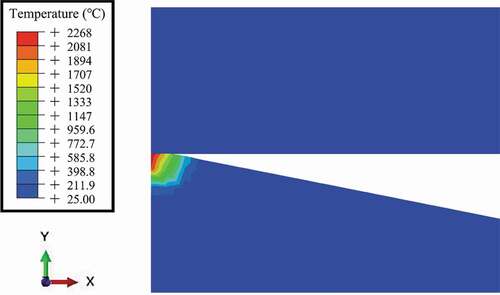
Figure 8. Dissipation energy of viscoelasticity (0.6 MPa).
The above results show that the energy dissipation due to viscoelasticity initially occurs when ultrasonic vibration is applied when the pressing pressure is low and a triangular ED is used. Then, the dissipated energy is converted into heat, which increases the temperature of the ED, accelerates the apparent time according to the Arrhenius-type time-temperature superposition principle, and reduces the apparent
Appendix 1 stiffness. The apparent time is accelerated by the Arrhenius-type time-temperature superposition principle, and the apparent stiffness is reduced, suggesting that the process results in the melting of the ED. shows the temperature change of the ED with time under a stress of 4.5 MPa, which shows that the temperature of the flat ED increases after the 10th stress, unlike that under a stress of 0.6 MPa. The time variation of the energy dissipation due to viscoelasticity and friction is shown in . For both viscoelasticity and friction, the energy dissipation of the flat ED gradually increased up to the 9th stress loading and then rapidly increased at the 10th stress loading. First, we discuss the stress loading up to the 9th time. Because the slope of the frictional dissipative energy is more pronounced than that of the viscoelastic dissipative energy, heat generation due to the frictional dissipative energy occurs first at the interface according to EquationEquation (5)(5)
(5) , and the ED temperature increases. Then, the apparent time is accelerated according to the Arrhenius-type time-temperature superposition principle, and the apparent stiffness decreases. Therefore, the ED deforms, and the viscoelastic dissipated energy increases according to EquationEquation (6)
(6)
(6) . Next, the tenth
Appendix 1 stress loading is described. In the present analysis, a rapid temperature increase was observed when the temperature reached approximately 80 °C. As the temperature rises, the dissipated energy of viscoelasticity increases according to the Arrhenius time-temperature superposition principle; thus, the temperature increases further, which further increases the dissipated energy. This means that the ED is in a coupled state. In the case of the model assumed in this analysis, the point at which the coupled state became pronounced was around 80 °C. However, even in the case of other characteristics, it is thought that the above coupled state appears when the temperature rises to some extent.
Figure 9. Dissipation energy of friction (0.6 MPa).
Figure 10. Temperature histories of the polymer (4.5 MPa).
Figure 11. Dissipation energy of viscoelasticity (4.5 MPa).
In actual ultrasonic welding, the vibration energy, pressure, and welding time are the main parameters that affect the welding quality. In this study, we found that the ED temperature increased rapidly regardless of the shape of the ED. This may make it difficult to optimize the parameters, which may affect the progress of research on ultrasonic welding.
In the present analysis, the specific heat and density values were set to lower values and the heat capacity was set to higher values in order to simulate 20 kHz ultrasonic vibration at 10 Hz. The temperature rise of triangular EDs is faster than that of flat EDs, which is qualitatively consistent with the results of previous studies [Citation1,Citation25]; that is, they can be welded with less vibration energy. It is a future task to discuss the temperature rise rate quantitatively. Furthermore, for simplicity, the specific heat was assumed to be constant regardless of the temperature, which resulted in the divergence of the ED temperature. However, because the specific heat depends on the temperature, the heat generation due to energy dissipation should converge. The temperature dependence of the specific heat is another issue to be analyzed in the future.
3.3 Temperature distribution of the energy director
The time variation of the temperature distribution of the triangular ED under a stress of 4.5 MPa is shown in . The vertices in contact with the composite material generate heat locally, indicating a temperature difference inside the ED. The temperature distribution of the flat ED under 4.5 MPa is shown in .
Figure 12. Dissipation energy of friction (4.5 MPa).
Figure 13. Temperature distribution of Triangular ED (4.5 MPa); (a) 0.010 s, (b) 0.011 s.
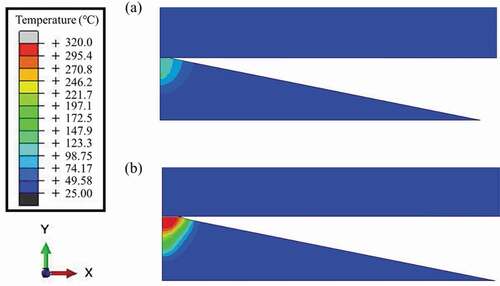
Figure 14. Temperature distribution of Flat ED (4.5 MPa); (a) 0.945 s, (b) 0.946 s.
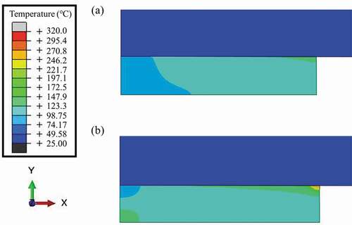
As shown in the , compared to the triangular ED, the heat is generated relatively evenly inside the flat ED. If there is a temperature difference inside the ED during the welding process, the ED may burn because of the simultaneous existence of melted and unmelted parts. Therefore, the present analysis indicates that unexpected chemical reactions may occur due to localized and excessive heating when using a triangular ED compared to a flat ED.
It should be noted that this study is only a qualitative study because it is two-dimensional, and the frequency is smaller than that of ultrasound. In the future, we will develop an analytical method that enables quantitative discussions by extending the method to three dimensions and considering analytical devices to simulate realistic ultrasonic frequencies.
4. Conclusion
In this study, a two-dimensional model of two types of EDs used in ultrasonic welding was developed, and the temporal changes in deformation, temperature, and dissipated energy were compared. The deformation of the triangular ED started earlier than that of the flat ED. In addition, the higher the stress applied, the higher the amount of heat generated. Therefore, compared with a flat ED, the triangular ED may require less welding energy and shorten the welding time. The heat generation process of the ED was suggested to be a coupled state of energy dissipation due to viscoelasticity, energy dissipation due to friction, and temperature rise, which may lead to a rapid temperature Appendix 1 rise. Therefore, the aforementioned rapid temperature rise may be a factor in the difficulty of optimizing the pressure, frequency, and welding time in ultrasonic welding. While the temperature inside the flat ED was relatively uniform, the triangular ED had a localized temperature distribution at the apex, resulting in a large temperature difference inside it. In other words, the triangular ED has the potential to reduce the welding energy and shorten the welding time, but the local heating may be excessive, and thus unexpected chemical reactions may occur.
Disclosure statement
No potential conflict of interest was reported by the author(s).
Additional information
Funding
References
- Levy A, Le Corre S, Fernandez Villegas I. Modeling of the heating phenomena in ultrasonic welding of thermoplastic composites with flat energy directors. J Mater Process Technol. 2014;214(7):1361–1371.
- Gouin O’Shaughnessey P, Dubé M, Fernandez Villegas I. Modeling and experimental investigation of induction welding of thermoplastic composites and comparison with other welding processes. J Compos Mater. 2016;50(21):2895–2910.
- Yousefpour A, Hojjati M, Immarigeon JP. Fusion Bonding/Welding of thermoplastic composites. J Thermoplast Compos Mater. 2004;17: 303–341
- Yousefpour A, Hojjati M, Immarigeon J-P. Fusion bonding/welding of thermoplastic composites. J Thermoplast Compos Mater. 2004;17(4):303–341.
- Wang K, Shriver D, Banu M, et al. Performance prediction for ultrasonic spot welds of short carbon fiber-reinforced composites under shear loading. J Manuf Sci Eng. 2017;139(11):111001–111010.
- Sakai T, Shamsudim NSB, Fukushima R, et al. Effect of matrix crystallinity of carbon fiber reinforced polyamide 6 on static bending properties. Adv Compos Mater. 2021;30(sup2):71–84.
- Fukushima R, Yamada Y, Kageyama K, et al. Effect of heat treatment on mechanical properties of carbon-fiber-reinforced themoplastic. Adv Compos Mater. 2021;30(6):527–543.
- Villegas IF, van Moorleghem R. Ultrasonic welding of carbon/epoxy and carbon/PEEK composites through a PEI thermoplastic coupling layer. Compos Part A Appl Sci Manuf. 2018;109:75–83.
- Tanabe D, Nishiyabu K, Kurashiki T. Effects of heating condition on high-frequency welding for thermoplastic CFRP laminates. JSME (in Japanese). 2015;81:1–13.
- Mizukami K, Mizutani Y, Todoroki A, et al. Detection of defects in thermoplastic CFRP welded zones using eddy current thermo-sensing. Trans. JSME (in Japanese). 2014;80(812):SMM0084–SMM0084.
- Villegas IF. In situ monitoring of ultrasonic welding of thermoplastic composites through power and displacement data. J Thermoplast Compos Mater. 2015;28(1):66–85.
- Roopa Rani M, Rudramoorthy R. Computational modeling and experimental studies of the dynamic performance of ultrasonic horn profiles used in plastic welding. Ultrasonics. 2013;53(3):763–772.
- Tao W, Su X, Wang H, et al. Influence mechanism of welding time and energy director to the thermoplastic composite joints by ultrasonic welding. J Manuf Process. 2019;37:196–202.
- Goto K, Imai K, Arai M, et al. Shear and tensile joint strengths of carbon fiber-reinforced thermoplastics using ultrasonic welding. Compos Part A Appl Sci Manuf. 2019;116:126–137.
- Palardy G, Villegas IF. On the effect of flat energy directors thickness on heat generation during ultrasonic welding of thermoplastic composites. Compos Interfaces. 2017;24(2):203–214.
- Palardy G, Shi H, Levy A, et al. “A study on amplitude transmission in ultrasonic welding of thermoplastic composites. Compos Part A Appl Sci Manuf. 2018;113:339–349.
- Benatar A. Ultrasonic welding of thermoplastic composites. Materials and Processing Report. 2016;3:1–10.
- Levy A, Le Corre S, Chevaugeon N, et al. A level set based approach for the finite element simulation of a forming process involving multiphysics coupling: ultrasonic welding of thermoplastic composites. J Mech A/Solids. 2011;30(4):501–509.
- Yang SQ, Dong Z, Yan JC, et al. SIMULATION ON HEATING PROCESS IN ULTRASONIC WELDING OF PLASTICS. Acta Metall Sin. 2000;13:80–83.
- Villegas IF, Moser L, Yousefpour A, et al. Process and performance evaluation of ultrasonic, induction and resistance welding of advanced thermoplastic composites. J Thermoplast Compos Mater. 2013;26(8):1007–1024.
- Tutunjian S, Dannemann M, Fischer F, et al. A control method for the ultrasonic spot welding of fiber-reinforced thermoplastic laminates through the weld-power time derivative. J Manuf Mater Process. 2018;3:1–17.
- Takeda S-I, Tanks JD, Sugimoto S, et al. Application of sheet-like energy directors to ultrasonic welding of carbon fibre-reinforced thermoplastics. Adv Compos Mater. 2021;30(2):192–204.
- Senders F, van Beurden M, Palardy G, et al. Zero-flow: a novel approach to continuous ultrasonic welding of CF/PPS thermoplastic composite plates. Adv Manuf Polym Compos Sci. 2016;2:83–92.
- Suresh KS, Rani MR, Prakasan K, et al. Modeling of temperature distribution in ultrasonic welding of thermoplastics for various joint designs. J Mater Process Technol. 2007;186(1–3):138–146.
- Takamura M, Uehara K, and Koyanagi J, et al. Multi-Timescale simulations of temperature elevation for ultrasonic welding of CFRP with energy director. Journal of Multiscale Modelling. 2021;12:214003. DOI:https://doi.org/10.1142/S1756973721430034
- Levy A, Corre SL, Poitou A. Ultrasonic welding of thermoplastic composites: a numerical analysis at the mesoscopic scale relating processing parameters, flow of polymer and quality of adhesion. Int J Mater Form. 2014;7(1):39–51.
- Wu X, Liu T, Cai W. Microstructure, welding mechanism, and failure of Al/Cu ultrasonic welds. J Manuf Processes. 2015;20:321–331.
- Tolunay MN, Dawson PR, Wang KK. Heating and bonding mechanisms in ultrasonic welding of thermoplastics. Polym Eng Sci. 1983;23(13):726–733.
- Balle F, Magin J. Ultrasonic spot and torsion welding of aluminum to titanium alloys: process, properties and interfacial microstructure. Phys Procedia. 2015;70:846–849.
- Nonhof CJ, Luiten GA. Estimates for process conditions during the ultrasonic welding of thermoplastics. Polym Eng Sci. 2004;36(9):1177–1183.
- Zhang C, Li L. A coupled thermal-mechanical analysis of ultrasonic bonding mechanism. Mater Process Sci. 2009;40:196–207.
- Koyanagi J, Nakada M, Miyano Y. Tensile strength at elevated temperature and its applicability as an accelerated testing methodology for unidirectional composites. Mech Time-Dependent Mater. 2012;16(1):19–30.
- Koyanagi J. Comparison of a viscoelastic frictional interface theory with a kinetic crack growth theory in unidirectional composites. Compos Sci Technol. 2009;69(13):2158–2162.