 ?Mathematical formulae have been encoded as MathML and are displayed in this HTML version using MathJax in order to improve their display. Uncheck the box to turn MathJax off. This feature requires Javascript. Click on a formula to zoom.
Abstract
Pupil stability is one of the factors which limit the performance and operational stability of adaptive optics (AO) systems. This paper analyses two pupil-tracking methods to measure the lateral pupil shift: the first one utilizes the fluxes in all outer edge sub-apertures of a Shack–Hartmann sensor and the second one utilizes the real-time interaction matrix used in an AO system. Experiments with 9 × 9 Shack–Hartmann sensor are conducted to verify both pupil-tracking algorithms. The results show that both algorithms are effective, after two correction steps, the residual pupil shift is reduced to less than 5% of a Shack–Hartmann sub-aperture.
1. Introduction
Nowadays, adaptive optics (AO) has become one of the key technologies for large ground-based telescopes (Citation1) and has been adopted in almost all 8–10 m class telescopes to improve their optical quality while observing through the turbulent atmosphere. To make full use of the AO system, the wavefront sensing channels and correcting device channels need to be registered precisely during closed-loop operation to guarantee optimal performance of the AO system (Citation2).
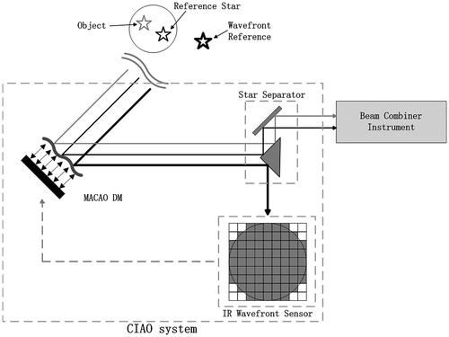
GRAVITY is an AO-assisted beam combiner for the second generation very large telescope (VLT) interferometer (VLTI) instrumentation (Citation3,4) within which there is a system named Coudé infrared adaptive optics (CIAO) (Citation5,6) used to ensure the required wavefront quality for the interferometer. Figure shows the schematic of a CIAO system, in total four CIAO units are available for GRAVITY to correct the wavefronts of the beams of the four telescopes of VLT. For each telescope, after being corrected by the deformable mirror (MACAO DM), the light is split into two parts by the Star Separator: the light of the wavefront reference (star) goes into the near-infrared (IR) wavefront Sensor, which composes the AO system together with the MACAO DM. The light of the object and the reference star goes into the Beam Combiner Instrument, where they interfere with the corresponding signals from other telescopes.
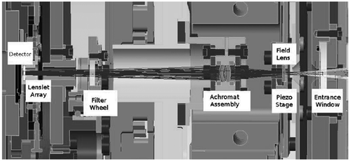
Misalignments or the motions of the optical elements between the deformable mirror and the Shack–Hartmann wavefront sensor (SHWFS) can induce both lateral and rotational pupil shifts during the telescope’s operation. These shifts lead to the mis-registration between the optical pupils defined by the DM and the wavefront sensor sub-apertures which are registered to the actuators of the DM. As a result, pupil shift can lead to the loss of light as well as the degradation of the performance of the AO system (Citation7). This paper focuses on the lateral pupil shift in the CIAO system which exists between the DM and SHWFS. A pupil actuator (field lens) located in CIAO cryostat can be used to stabilize the pupil position (Citation8) (Figure ). This requires a precise measurement of the actual pupil position.
Figure 2. Optical path inside the CIAO WFS cryostat. After entering the entrance window, the beam passes through a field lens (mounted on an X–Y piezo stage – N-111 NEXLINE OEM Linear Actuator) which can shift the pupil on two orthogonal directions, an achromatic doublet, and a filter (mounted in a filter wheel), before imaging the pupil on the lenslet array and the detector.
This paper analyses two pupil-tracking methods: Section 2 describes the first method which utilizes the fluxes in all outer edge sub-apertures of the Shack–Hartmann sensor and Section 3 describes another method which utilizes the real-time interaction matrix obtained during the closed-loop control of the AO system. Experiments are conducted to verify these two methods; the results are shown, respectively, in Sections 2 and 3. In Section 4, we make a comparison of these two algorithms. Section 5 summarizes our conclusions.
2. The intensities method
2.1. Principle of the intensities method
The CIAO SHWFS is used here to illustrate the method. We use the 9 × 9 square microlens array of the CIAO SHWFS (Figure ) to measure the integrated fluxes in certain sub-apertures and detect whether the pupil is shifted. In the intensities method, we choose the fluxes in the 24 outer edge sub-apertures to measure the pupil shift.
Figure 3. Schematic of the CIAO lenslet array with pupil coverage. The grey circles define the ring-shaped illuminated area of the lenslet array, which ideally matches the geometrical size of the VLT’s M8 pupil.
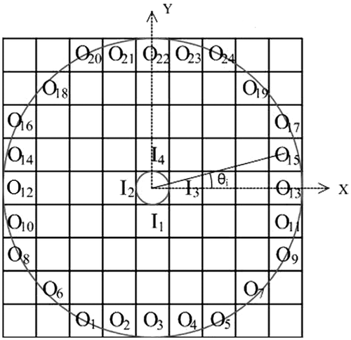
The integrated fluxes of the sub-apertures are marked with O1, O2, … , O24 (outer ring sub-apertures) and I1, I2, I3, I4 (inner ring sub-apertures). When the lateral pupil shift is smaller than the length of a sub-aperture, the pupil’s central position PX and PY can be calculated via Equations (Equation1(1)
(1) ) and (Equation2
(2)
(2) ):
(1)
(1)
(2)
(2)
where θi is the angle between the centre of the sub-aperture Oi and X-axis (Figure ).
2.2. Result of the experiment using the intensities method
We use the CIAO SHWFS in the laboratory to perform the experiment. As shown in Figure , the fluxes in the 24 outer edge sub-apertures of the 9 × 9 Shack–Hartmann sensor are used to measure the pupil shift. Due to the internal optical alignment of the wavefront sensor as well as the stroke of the pupil actuator, we could only introduce a lateral pupil shift between –0.4 and 0.4 in the length of a sub-aperture on the SHWFS, which corresponds to a shift of –0.36 to 0.36 m on the VLT’s primary mirror.
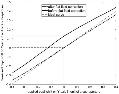
To verify the performance of the algorithm, we conduct the following experiment: we move the pupil’s centre along Y-axis from –0.4 to 0.4 sub-aperture while keeping the pupil’s centre on X-axis fixed at different values. We measure 200 frames of fluxes in the SHWFS at each position, and then use the intensities of all the 24 outer edge sub-apertures of each pupil’s position to calculate pupil’s shift PY. Finally, we compare PY with the applied shift to evaluate the performance of this algorithm. To compensate the deviation in the measurement of the pupil shift caused by the non-uniformity of the illumination in the pupil, a flat-field calibration is implemented. The measurement of pupil shift on X-axis is similar to the measurement of pupil shift on Y-axis. The result of the experiment is shown in Figure .
Figure 4. Variation of measured pupil shift PY on Y-axis by the intensities method due to the applied pupil shift ‘shifty’ on Y-axis while keeping pupil’s shift on X-axis ‘shiftx’ at different values. The dashed line represents the ideal result of the measured pupil shift.
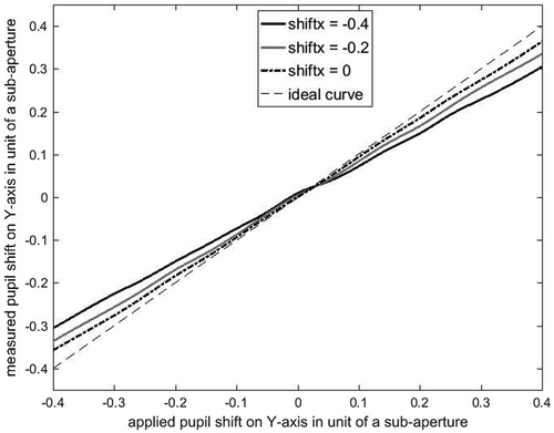
Figure shows that the measurement of the pupil shift on Y-axis is quite precise when ‘shiftx’ = 0 (the dot-dash-line), the maximal deviation is less than 0.05 sub-aperture. The deviation of the measurement gets larger as ‘shiftx’ departs from 0.
We adopt the maximal deviation between the measured pupil shift and the applied pupil shift to be the indicator to evaluate the performance of the algorithm. The result is shown in Figure . As the range of the applied pupil shift on Y-axis shrinks from ±0.4 (–0.4 to 0.4 sub-aperture) to 0, while keeping ‘shiftx’ at 0, the maximal deviation (dotted curve) reduces from 0.042 to 0, other curves which represent different ‘shiftx’ also have the same tendency. On the other hand, as ‘shiftx’ varies from –0.4 to 0, the average values of the curves also decline, which means the deviation of the measurement is reduced when ‘shiftx’ decreases. The results of the measurements, when ‘shiftx’ varies from 0 to 0.4, are not shown here because they are basically the same with the results when ‘shiftx’ varies from 0 to –0.4.
Figure 5. Variation of the maximal deviation between the measured and applied pupil shift on Y-axis due to the stroke/range of the applied pupil shift on Y-axis. The diamond blocks mark the residual pupil shifts after each correction.
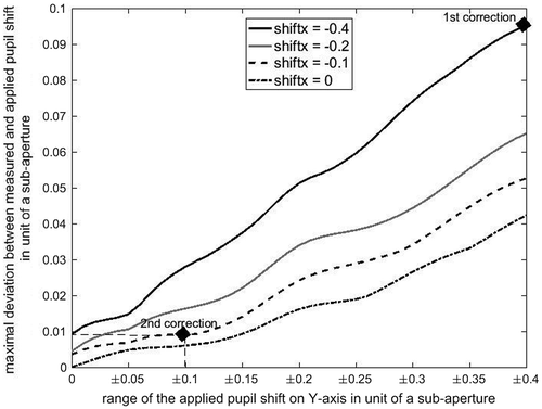
The maximum of the maximal deviations of the measured pupil shift in Figure is 0.095 sub-aperture (the diamond block marked with ‘1st correction’). It means for an initial pupil shift within –0.4 to 0.4 sub-aperture on both axes, the residual pupil shift after one pupil shift correction will decrease to under 0.095 sub-aperture. Furthermore, this residual deviation decreases to less than 0.01 sub-aperture (the ‘2nd correction’ diamond block) after performing the correction for the second time. In CIAO, the budget of the wavefront error caused by the misalignment between the DM and the SHWFS is 50 nm, which corresponds to a residual pupil shift after the correction of 10% of the length of a sub-aperture (Citation9,10). As the smaller the pupil shift is, the better the CIAO system works, here we adopt a stricter demand: 5% of the length of a sub-aperture – this could be achieved within two correction steps with the intensities method when the initial pupil shift on both axes are within –0.4 to 0.4 sub-aperture.
2.3. Using additional sub-apertures
For completeness, we consider another similar algorithm in which the four inner sub-apertures are also utilized. The formulas of this algorithm are:(3)
(3)
(4)
(4)
The factor 2 in Equations (Equation3(3)
(3) ) and (Equation4
(4)
(4) ) is to normalize the value of the formula to 1 or –1 when the pupil shift is an entire sub-aperture in either positive or negative direction.
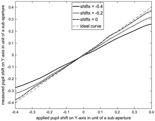
We analyse the data with this algorithm to compare it with the former one which just utilizes the outer sub-apertures. The result is shown in Figure . Compared with Figure , although when ‘shiftx’ = 0, the precision of the measurement in Figure is pretty high, it degrades when ‘shiftx’ departs from 0 – even approaches about 0.15 sub-aperture when ‘shiftx’ = –0.4 and ‘shifty’ = 0.4 – which means the precision of the algorithm degrades fast when the pupil shift departs from the axes. As a result, in general, the performance of the algorithm which only utilizes the fluxes in the 24 outer sub-apertures is better than the one which utilizes the fluxes in both inner and outer sub-apertures.
Figure 6. Variation of measured pupil shift on Y-axis with the intensities method which utilizes both the 4 inner and 24 outer sub-apertures due to the applied pupil shift on Y-axis while keeping pupil’s shift on X-axis at different values. The dashed line represents the ideal result of the measured pupil shift.
2.4. Error discussion
2.4.1. Integration time
Disturbances and noises such as the atmosphere turbulence (to simulate the atmosphere turbulence in the actual observation, an artificial turbulence with a seeing of 0.5 arcsec is added in the experiment), photon noise and detector noise can induce errors to the measurement of the pupil shift and these errors can be reduced by gathering more frames of data in the experiment (in other words, extending the integration time). Assume is the variance of the measurement signal PX, to detect a pupil shift as small as 5% of a sub-aperture,
needs to be less than 10−4d2 with d as the length of a sub-aperture (which means an average measurement error of about 1% sub-aperture).
We test the impact of the number of gathered frames in our experiment on the variance of the measured pupil shift for the intensities algorithms. The result is shown in Figure (grey curve).
Figure 7. Variation of the variance of measured pupil shifts due to the number of frames gathered in the experiment.
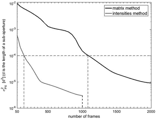
The grey curve in Figure shows that the variance of the measurement for the intensities algorithms decreases as more frames are gathered. If we want to reduce to less than 10−4d2, the least number of frames that should be gathered for the intensities method is 150. In fact, we set the number to 200 in our experiment. As the frequency of the AO closed-loop operation is 500 Hz, the integration time is 0.4 s.
2.4.2. Non-uniformity of the illumination of the pupil
The pupil in the experiment is not illuminated uniformly, this non-uniformity leads to deviation in the intensities method – it causes a deviation of 0.13 sub-aperture – when the pupil’s centre is at the original point.
A flat-field calibration is implemented to eliminate the deviation and it records the intensities in the sub-apertures when the pupil’s centre is at the original point. Every frame of intensity data has to be divided by this calibration frame before further process. Figure shows the comparison of the measurements of the pupil shift before and after the flat-field calibration with ‘shiftx’ = 0. The deviation caused by the non-uniformity of the illumination in the pupil is significantly eliminated after implementing the flat-field calibration.
2.4.3. Precision of the pupil actuator
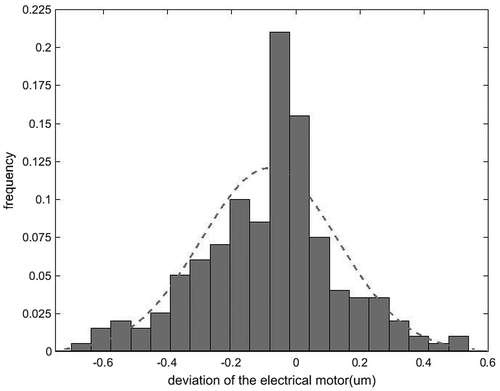
The pupil position located on the lenslet array of the SHWFS is moved via a pupil actuator based on an internal piezo walk mechanism. The precision of this actuator determines the precision of the applied pupil shift in the experiment. As the length of a sub-aperture of the SHWFS in our experiment corresponds to a pupil actuator motion of 300 μm and we want the deviation caused by the pupil actuator to be smaller than 1% of a sub-aperture, the location precision of the actuator needs to be smaller than 3 μm. We test the error distribution for this actuator in the stroke –0.4 to 0.4 sub-aperture, the result is shown in Figure .
The error distribution of the actuator complies with a Gaussian distribution whose mean value is –0.08 μm and standard deviation is 0.21, thus the precision of the actuator is –0.50 to 0.34 μm with a confidence interval of 95% – which is much smaller than 3 μm, as a result, the deviation caused by the pupil actuator can be neglected in our analysis.
2.4.4. Pupil rotation
Pupil rotation can lead to the change of the intensities’ distribution in the SH sensor. But in our experiment, the piezo walk mechanism can only move the pupil along two orthogonal directions, therefore the pupil rotation is negligible.
3. The matrix method
3.1. Principle of the matrix method
The matrix method computes the pupil shift by comparing two interaction matrices (IM) of the DM which are measured, respectively, before and during the closed-loop AO operation. The former IM is also called the nominal IM (M0) which is obtained when the applied pupil shift is zero.
Figure shows the structures of matrix M0 in CIAO SHWFS, as each of the 68 sub-apertures has two tilts (X and Y directions), M0 can be decomposed into M0X and M0Y. Because there are 60 actuators on the back of the DM and each actuator has its own IM, both M0X and M0Y are 60 × 68 matrices. The DM’s IM varies when the pupil shifts during the closed-loop AO operation. Let M1 be the real-time DM’s IM obtained during the closed-loop AO operation, M1 has the same structure as M0 and can be decomposed into M1X and M1Y.
Figure 10. Schematics of M0 with pupil coverage. The grey circles define the ring-like illuminated area of the lenslet array. Only the 68-squared sub-apertures with at least 50% of their area covered by the pupil are used for wavefront sensing. M0 is decomposed to M0X (left figure) and M0Y (right figure). Sxij and Syij (i = 1,2, … , 60; j = 1,2, … , 68) are the tilts in the valid sub-apertures on X and Y directions of every actuator. (M1 has the same structure with M0, but its tilts are signed as Sx’ij and Sy’ij).
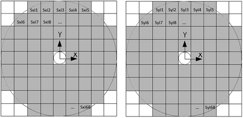
To apply the matrix algorithm, we need to differentiate the matrix M0 on X and Y directions to get two new matrices, dM0X and dM0Y, which represent M0’s gradients on the two directions. Figure shows the structures of dM0X and dM0Y. As with M0X and M0Y, both dM0X and dM0Y are 60 × 68 matrices.
Figure 11. Schematics of dM0X (left figure) and dM0Y (right figure),which are obtained by differentiating M0X and M0Y on X and Y directions. dSxij and dSyij (i = 1,2, … , 60; j = 1,2, … , 68) are the differentiations of Sxij and Syij in M0X and M0Y.
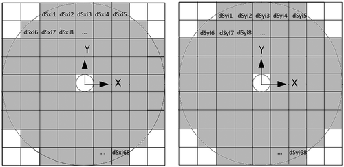
The matrix method uses M0, M1 and dM0 to calculate the pupil shift. Assume a pupil shift (PX, PY) which is much smaller than the length of a sub-aperture and the corresponding real-time IM obtained in the AO closed-loop control is M1. Because the shift is small, we have:(5)
(5)
Equation (Equation5(5)
(5) ) with least square estimation, PX and PY can be written as:
(6)
(6)
As PX or PY is just a number instead of a matrix, Equation (Equation6(6)
(6) ) can be written as:
(7)
(7)
3.2. Result of the experiment using the matrix method
We conduct the experiment of the matrix method on the CIAO bench in the lab. As shown in Figure , there are 68 sub-apertures in the SH sensor, each sub-aperture can measure the average wavefront slopes at X and Y directions in every frame. The deformable mirror (MACAO DM) has 60 actuators and we need to measure the voltages applied to the 60 actuators to calculate the real-time IM. Assume a DM command Ccomm and the SHWFS’s measurement Wmeas after performing Ccomm, we have:(8)
(8)
where Tturb is the atmosphere turbulence during the SHWFS’s measurement and M1 is the real-time interaction matrix. Furthermore, we have:(9)
(9)
where:
| M1 | = | is the real-time IM (dimension: 136 × 60), |
| Δmeas | = | is the difference between two successive SHWFS measurements (dimension 136 × 1), |
| Δcomm | = | is the difference between two successive DM command vectors (dimension 60 × 1), |
| Δturb | = | is the turbulence increment between the two successive frames |
We are able to measure a wealth of pairs (Δmeas, Δcomm) by acquiring slopes and voltages data. As Δturb is uncorrelated from Δcomm, it can be considered just like a ‘noise’ term. Thus, getting plenty of measurements allow us to solve Equation (Equation9(9)
(9) ) for M1 by the least square estimation. Assume
and
with N the number of frames acquired, M1 can be calculated:
(10)
(10)
The experiment is conducted as follows: move the pupil’s centre along Y-axis from –0.4 to 0.4 sub-aperture while keeping the pupil’s centre on X-axis fixed at different values. We measure 2000 frames of the slopes in the 68 sub-apertures of the SH sensor and the voltages of the 60 actuators during the closed-loop control at each pupil position, then make use of the slopes and voltages to calculate M1 with Equation (Equation10(10)
(10) ). Finally, we compute the pupil shift by comparing M1 with the nominal IM M0 using Equation (Equation7
(7)
(7) ).
The result of the experiment is shown in Figure : the matrix method works well when ‘shiftx’ is small, but its precision degrades fast as ‘shiftx’ departs from 0, the maximal deviation reaches more than 50% when ‘shiftx = –0.4’. To evaluate the performance of the measurement, we adopt the maximal deviation between the measured pupil shift and the applied pupil shift to be the indicator. As the deviation of the measurement is too high, when the pupil centre gets far from the original point, we verify this algorithm’s performance when the applied pupil shift is within only –0.2 to 0.2 sub-aperture on both axes. The result is shown in Figure .
Figure 12. Variation of measured pupil shift on Y-axis PY with the matrix method as a function of the applied pupil shift on Y-axis ‘shifty’ while keeping pupil’s shift on X-axis ‘shiftx’ fixed at different values. The dashed line represents the ideal result of the measured pupil shift.
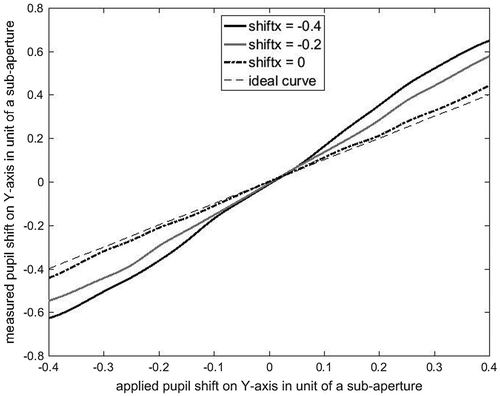
Figure 13. Variation of the maximal deviation between the measured and applied pupil shift on Y-axis measured by the matrix method due to the stroke/range of the applied pupil shift on Y-axis. The diamond blocks mark the residual pupil shifts after each correction.
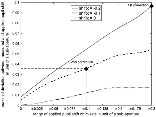
Figure shows that the average values of the curves decline when ‘shiftx’ varies from –0.2 to 0, in addition the maximal deviations also decrease as the range of applied pupil shift on Y-axis (‘shifty’) shrinks from ±0.2 (–0.2 to 0.2 sub-aperture) to 0. The deviation of the pupil shift measured by this algorithm decreases fast after applying multiple pupil shift corrections. The two diamond blocks in Figure show that an initial pupil shift within –0.2 to 0.2 sub-aperture on both axes can be reduced to 0.097 and 0.036 length of a sub-aperture after 1 and 2 pupil shift correction steps, which means the requirement on residual pupil shift – 5% of the sub-aperture – can be achieved within two correction steps with the matrix method.
3.3. Error discussion
3.3.1. Integration time
We test the impact of the number of gathered frames in our experiment on the variance of the measured pupil shift for the matrix algorithm. The result is shown in Figure (black curve).
The black curve in Figure shows the variance of the measurements for the matrix algorithm decreases as more frames are gathered. To reduce to less than 10−4d2, the least number of frames that should be gathered is 1100. In fact, we set the number to 2000 in our experiment. As the frequency of the AO closed-loop operation is 500 Hz, the integration time is 4 s.
3.3.2. Pupil rotation and the precision of the pupil actuator
Pupil rotation can lead to the mis-registration seen by the interaction matrix of the AO system. But in our experiment, the piezo walk mechanism can only move the pupil along two orthogonal directions, thus the pupil rotation is negligible.
The pupil actuator used in the experiment for the matrix method is identical with the one used for the intensities method. Thus, the result of the test shown in 2.4.3 is still valid here, which means the deviation caused by the pupil actuator can be neglected in the experiment of the matrix algorithm.
4. Comparison of the two algorithms
Table shows the comparison of the two algorithms. Firstly, in our experiment, the deviation of the matrix algorithm reaches more than 50% when the pupil shift’s range exceeds –0.2 to 0.2 sub-aperture, while the intensities algorithm can keep the deviation lower than 25% within the range –0.4 to 0.4 sub-aperture, thus the intensities algorithm has a larger valid range. Secondly, compared with the matrix algorithm’s 4 s integration time, the intensities algorithm only needs a 0.4 s integration time, which makes it more suitable for those situations which need high-frequency pupil corrections. Thirdly, unlike the intensities algorithm, the matrix algorithm does not directly utilize the fluxes in the sub-apertures, thus it has a lower requirement on the brightness of the observed object and is more suitable for observing faint science objects.
Table 1. Comparison of the intensities algorithm and the matrix algorithm.
Generally, the intensities algorithm works better in situation with bright object, high-frequency pupil correction and large pupil shift, while the matrix algorithm is more suitable for situation with faint object, low-frequency pupil correction and small pupil shift.
5. Conclusion
We analyse two pupil-tracking methods which can measure the lateral pupil shift with a SH sensor based on AO system. The first one utilizes the fluxes in all outer edge sub-apertures of a Shack–Hartmann sensor and the second one utilizes the real-time interaction matrix obtained during closed-loop operation of the AO system. We conduct two experiments with the CIAO system to verify these pupil-tracking algorithms. The results of the experiment show that both algorithms are effective, after two correction steps, the residual pupil shift is reduced to less than 5% of a sub-aperture. The intensities algorithm works better in situation with bright object, high-frequency pupil correction and large pupil shift, while the matrix algorithm is more suitable for situation with faint object, low-frequency pupil correction and small pupil shift.
Disclosure statement
No potential conflict of interest was reported by the authors.
References
- Davies, R.; Kasper, M. Adaptive Optics for Astronomy. Annu. Rev. Astron. Astrophys. 2012, 50, 305–351.10.1146/annurev-astro-081811-125447
- Montagnier, G.; Fusco, T.; Beuzit, J.-L.; Mouillet, D.; Charton, J.; Jocou, L. Pupil Stabilization for SPHERE’s Extreme AO and High Performance Coronagraph System. Opt. Exp. 2007, 15, 15293–15307.10.1364/OE.15.015293
- Eisenhauer, F.; Perrin, G.; Brander, W.; Christian Straubmeier; Karine Perraut; António Amorim; Markus Schöller; Stefan Gillessen; Pierre Kervella; Myriam Benisty; Constanza Araujo-Hauck; Laurent Jocou; Jorge Lima; Gerd Jakob; Marcus Haug; Yann Clénet; Thomas Henning; Andreas Eckart; Jean-Philippe Berger; Paulo Garcia; Roberto Abuter; Stefan Kellner; Thibaut Paumard; Stefan Hippler; Sebastian Fischer; Thibaut Moulin; Jaime Villate; Gerardo Avila; Alexander Gräter; Sylvestre Lacour; Armin Huber; Michael Wiest; Axelle Nolot; Pedro Carvas; Reinhold Dorn; Oliver Pfuh; Eric Gendron; Sarah Kendrew; Senol Yazici; Sonia Anton; Yves Jung; Markus Thiel; Élodie Choquet; Ralf Klein; Paula Teixeira; Philippe Gitton; David Moch; Frédéric Vincent; Natalia Kudryavtseva; Stefan Ströbele; Eckhard Sturm; Pierre Fédou; Rainer Lenzen; Paul Jolley; Clemens Kister; Vincent Lapeyrère; Vianak Naranjo; Christian Lucuix; Reiner Hofmann; Frédéric Chapron; Udo Neumann; Leander Mehrgan; Oliver Hans; Gérard Rousset; Jose Ramos; Marcos Suarez; Reinhard Lederer; Jean-Michel Reess; Ralf-Rainer Rohloff; Pierre Haguenauer; Hendrik Bartko; Arnaud Sevin; Karl Wagner; Jean-Louis Lizon; Sebastian Rabien; Claude Collin; Gert Finger; Richard Davies; Daniel Rouan; Markus Wittkowski; Katie Dodds-Eden; Denis Ziegler; Frédéric Cassaing; Henri Bonnet; Mark Casali; Reinhard Genzel; Pierre Lena. GRAVITY: Observing the Universe in Motion. Messenger 2011, 143, 16–24.
- Gillessen, S.; Eisenhauer, F.; Perrin, G. GRAVITY: A Four-telescope Beam Combiner Instrument for the VLTI. Proc. SPIE 2010, 7734, 77340Y.10.1117/12.856689
- Kendrew, S.; Hippler, S.; Brandner, W. GRAVITY Coudé Infrared Adaptive Optics (CIAO) System for the VLT Interferometer. Proc. SPIE 2013, 8446, 84467W.
- Scheithauer, S.; Brandner, W.; Casey P. Deen; Tobias Adler; Henri M. Bonnet; Pierre Bourget; Fanny Chemla; Yann Clénet; Françoise Delplancke-Stroebele; Monica Ebert; Frank Eisenhauer; Michael Esselborn; Gert Finger; Éric Gendron; Adrian Glauser; Frédéric Yves Joseph J. Gonté; Thomas Henning; Stefan Hippler; Armin Huber; Zoltan Hubert; Gerd Jakob; Liselotte Jochum; Laurent Jocou; Sarah Kendrew; Ralf Klein; Johann Kolb; Martin Kulas; Werner Laun; Rainer Lenzen; Marcus Mellein; Eric Müller; Javier Moreno-Ventas Mateos; Udo Neumann; Sylvain Oberti; Jürgen Ott; Laurent Pallanca; Johana Panduro; José R. Ramos; Miguel Riquelme; Ralf-Rainer Rohloff; Gérard Rousset; Nicolas Schuhler; Marcos Suárez Valles; Gérard Zins. CIAO – Wavefront Sensors for GRAVITY. Proc. SPIE 2016, 9909. Submitted for publication.
- Clénet, Y.; Gendron, E.; Rousset, G. Dimensioning the Gravity Adaptive Optics Wavefront Sensor. Proc. SPIE 2010, 7736, 77364A.10.1117/12.856661
- Deen, C.; Yan, P.; Huber, A. Integration and Bench Testing for the GRAVITY Coude IR Adaptive Optics (CIAO) Wavefront Sensor. Proc. SPIE 2014, 9148, 91482T-1.
- Hippler, S.; Brandner, W. VLTI GRAVITY Phase C: Wavefront Sensor System Design; Technical Report of ESO Project GRAVITY, Doc No. VLT-TRE-GRA-15881-5101: Heidelberg, 2014.
- Clenet, Y.; Gendron, E. VLTI GRAVITY Phase C: Wavefront Sensor Adaptive Optics Performance; Technical Report of ESO Project GRAVITY, Doc No. VLT-TRE-GRA-15882-5201: Heidelberg, 2012.

