Abstract
The decrease in dislocation density and hence the high strength loss can be modelled during martensite tempering as a recovery process. In this work, an innovative approach is presented to understand the role of silicon associated with the inhibition of the recovery rate. A phenomenological model is presented, where a combination of cross-slip and solute drag is identified as the main governing mechanism for recovery up to 450 C, from where it is postulated that recrystallisation occurs.
1. Introduction
The microstructural changes occurring during martensite tempering can be described as a recovery process [Citation1,Citation2]. Recovery is a process that takes place during the annealing of plastically deformed materials, which leads to a change of the dislocation microstructure without the migration of a high-angle grain boundary [Citation3,Citation4]. As-quenched martensite adopts a complex microstructure consisting of various sub-structures, where laths are separated by low-angle grain boundaries (15
) [Citation5]. When recovery takes place during tempering, the stored energy in the material decreases by a change in the dislocation structure by dislocation annihilation, dislocation rearrangement and sub-grain growth [Citation6]. The lower energy configuration is achieved by the movement of individual dislocations by glide, climb and cross-slip. The dominant process determines the rate of recovery. Additionally, where significant alloying exists, solute drag effects also become significant. For a detailed description of each of these processes, the readers are referred to the comprehensive review by Nes [Citation7].
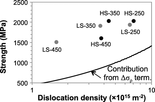
In a previous work by the authors where strengthening mechanisms of medium-carbon (0.5–0.6 wt.%) steels were unveiled, it was shown that the reduction in the dislocation density during tempering is what leads to the loss in ultra high strength of martensite. Furthermore, it was proposed that silicon plays an inhibiting role in martensite recovery during tempering [Citation8]. Recovery results in a reduction in the dislocation density, and the rate at which such reduction took place was seen to be slower in the presence of silicon. Given silicon’s relatively small size compared to other substitutional elements, it is considered in this work that its interaction with dislocations can be more pronounced. As shown in Figure , dislocation forest hardening () constitutes a significant proportion of the overall strengthening in tempered martensitic alloys (for more details, readers are referred to the extended work presented in [Citation8]). Therefore, it is the aim of this work to provide insight into the recovery mechanism, as well as to establish a connection between recovery and the loss in ultra-high strength properties during tempering under the influence of silicon.
Figure 1. Representation of the dislocation forest hardening contribution () to the yield strength of tempered martensitic steels. The dots on the graph represent the measured dislocation density (x-coordinate) and yield strength (y-coordinate) values of the material, where HS and LS represent high-silicon and low-silicon alloys, respectively, tempered at 250, 350 and 450
C.

2. Background to recovery
In this work, the extent of recovery will be quantified by the dislocation density reduction rate, making use of recovery models from literature to determine which recovery mechanism adjusts to our experimental data [Citation8].
The two mechanisms of highest relevance are: (i) thermally activated annihilation based on Friedel’s cross-slip mechanism [Citation9], and (ii) solute-drag controlled mechanisms. The former makes the assumption that the rate controlling factor is the dislocation annihilation reaction itself, and not so much the movement of dislocations into configurations where annihilation becomes possible. The latter takes into account the case of heavily alloyed systems.
For cross-slip, the rate of recovery is given by [Citation7]:(1a) where
is the instantaneous dislocation density,
is the initial dislocation density, t is the time and
is the relaxation time parameter for cross-slip, C is a constant,
is the activation energy for cross-slip, R is the gas constant and T is the absolute temperature.
The solute drag controlled recovery rate is given by [Citation7]:(1b) where k is the Boltzmann constant,
is the relaxation time parameter for solute drag, a is a constant in the order of unity,
is the distance between solute pinning points and is taken to be
where
is the solute concentration, G is the shear modulus, and b is the Burgers vector.
is the temperature-dependent parameter for solute diffusion,
is a constant,
is a vibrational frequency term, and
is similar to the activation energy for bulk diffusion of the solute.
Essentially, Equation (2d) incorporates the thermally activated diffusion process of the solute. Therefore, this expression can be approximated by the more familiar case of silicon diffusion in -Fe,
. Equation (2b) thus becomes:
(2a)
3. Experimental procedure
Two quenched-and-tempered medium-carbon steels are considered in the current study: HS (high silicon, Fe-0.56C-2.30Si-0.69Mn-0.89Cr wt.%) and LS (low silicon, Fe-0.55C-1.43Si-0.72Mn-0.91Cr wt.%), where details on other microalloying elements can be found in [Citation8].
The dislocation density values obtained from a previous work by the authors [Citation8] are used in the current study. The dislocation density was estimated from the microstrains obtained using the line-broadening method in X-ray diffraction (XRD), where measurements were made using high-energy X-rays from a synchrotron source. The samples were heat treated in an Adamel Lhomargy dilatometer (DT1000), and initially were cylinders of 3 mm diameter and 12 mm length. These were then machined into needles of 0.5 mm diameter and 6 mm length prior to XRD (details on the procedure are found in [Citation10] and [Citation8]).
In order to observe the microstructural evolution of tempered martensite, transmission electron microscopy (TEM) was carried out using a Philips CM30 microscope. The heat treatments were perfomed in an Adamel Lhomargy dilatometer (DT1000) using cylinderical rods of 3 mm in diameter and 12 mm long. 3 mm discs were then cut from the dilatometry samples, and electropolished using a solution composed of 15 ml perchloric acid and 85 mm ethanol. A twinjet electropolisher Struers Tenupol-5 was used, operated under a voltage of 20.5 V, at 16 C, and a flow rate set at 12.
4. The model
The expressions for cross-slip and solute-drag will be used to model the reduction in during tempering against the experimentally obtained values. For modelling cross-slip, the parameters used for determining
were
kJ/mol [Citation11], and C was fitted to be
. For modelling solute drag,
for HS and 11.02 for LS,
nm for HS and 0.2483 nm for LS assuming the
Burgers vector.
GPa [Citation12], and
)
) [Citation13], where
is the atomic fraction of silicon. Borg and Lai [Citation13] showed that in
-Fe–Si systems, the activation energy for the diffusion of silicon in
-Fe was around 220 kJ/mol, where
was seen to be decreased with increasing silicon content. In this study, the values used were
and 245 kJ/mol for HS and LS, respectively. Throughout modelling,
m
, and
s, which is the tempering time from the as-quenched condition.
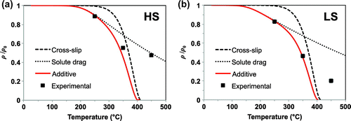
Figure shows the summary of the two expected dislocation density annihilation for HS and LS when solute drag and cross-slip meachanisms are compared. Based on Figure , the following observations can be made: in both HS and LS, assuming a solute-drag controlled mechanism of recovery underestimates the recovery kinetics, while on the other hand, the cross-slip controlled mechanism predicts a faster recovery than what is experimentally observed. Nevertheless, postulating that in reality a combination of both effects may occur, Equations (1) and (2) are combined, and it is proposed that annihilation can be represented as additive terms, yielding the following expression:(2b)
Figure 2. Modelling recovery considering cross-slip and solute drag mechanisms, and a combination of both processes, for (a) HS and (b) LS.

Using the exact same parameters as before, the dislocation density evaluation is shown as ‘Additive’ in Figure . For both HS and LS, the use of Equation (Equation4(2b) ) gives a closer agreement with the experimentally observed dislocation density reduction during tempering than the curves for solute drag and cross-slip. Nevertheless, in both cases, the combined function predicts a faster recovery rate than what is experimentally observed for the sample tempered at 450
C. A possible explanation is that at 450
C recovery becomes less relevant, and instead some recrystallisation might occur, releasing only partially the dislocation-related lattice strains in selected areas. The occurrence of recrystallisation in steels at such temperatures is not new, Borchers et al. [Citation14] have reported a transition between recovery and recrystallisation upon annealing of heavily deformed pearlitic wire, precisely when the temperature is increased from 400 to 450
C.
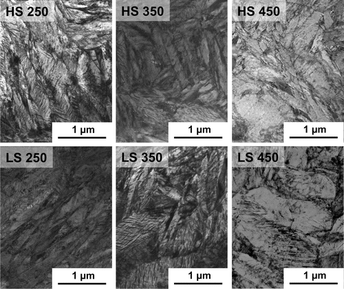
This is corroborated by the microstructural characterisation using TEM. Figure shows representative microstructures of the conditions HS 250, HS 350, HS 450, LS 250, LS 350 and LS 450. It can be clearly seen that the microstructures for the samples tempered at 250 and 350 C remain similar, consisting of elongated and narrow lath/plate features. However, the microstructure obtained after tempering at 450
C is different, where wider and globular-like lath units can be observed. Therefore, it is likely that a different process takes place when tempering at 450
C that leads to such differences in the microstrucure. This is consistent with the findings from modelling recovery, where at 450
C, the model predicts faster recovery kinetics than those experimentally observed.
5. Discussion and concluding remarks
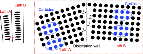
It should also be noted that during martensite tempering, carbide precipitation also occurs additional to the process of recover. Both processes may take place simultaneously within the microstructure, leading to some interaction between the two. However, as experimentally observed in Figure and illustrated in Figure , while the microstructure consists of intralath carbides, where carbide precipitation predominantly occurs within the central region of the martensitic laths, recovery is a localised process that takes place at low-angle grain boundaries, e.g. lath boundaries. There is a possibility that a long-range interaction exists between a dislocation stress field and the distorted matrix surrounding a carbide, but such interaction may be treated as a constant term in the recovery kinetics. Whether it will have an accelerating or an inhibiting effect, it is not known presently. The current model also has its limitation in that it does not take into account the carbon that may be segregated in lath boundaries. As recovery proceeds and some lath boundaries disappear, the trapped carbon would be released back into the matrix and be consumed in carbide precipitation. Hence, a more complex interaction between precipitation and recovery may occur, even under static conditions.
Figure 4. Schematic representation of intralath precipitation and recovery of low-angle grain boundaries.

In summary, the evolution in dislocation density throughout the tempering of martensitic steels can be modelled as a recovery process. From this study, it is concluded that both solute drag and cross-slip are mechanisms by which recovery occurs, and that silicon has an inhibiting role in recovery kinetics. Having identified the mechanisms controlling dislocation behaviour, it is possible to model the dislocation density given the time–temperature conditions of tempering. This is valid for temperatures below 450 C, as around this temperature, recrystallisation is proposed to occur. This is also supported by microstructural evidence, where at 450
C, a different microstructure is observed than at lower temperatures.
Acknowledgements
All the experimental work presented in this work was carried out during B.K.’s PhD studies at the Department of Materials Science and Metallurgy (University of Cambridge), for which B.K. and P.E.J.R. are grateful to Prof. A.L. Greer and Prof. M.G. Blamire for the provision of laboratory facilities and would like to acknowledge ASCOmetal for financial support. D.S.M. would like to acknowledge the financial support to Spanish Ministerio de Economia y Competitividad (MINECO) through in the form of a Coordinated Project (MAT2013-47460-C5-1-P) and the experimental support of Mr. Javier Vara.
Additional information
Funding
Notes
No potential conflict of interest was reported by the authors.
References
- R.N. Caron and G. Krauss, The Tempering of Fe-C Lath Martensite, Metall. Trans. 3 (1972), pp. 2381–2389.
- G.R. Speich and W.C. Leslie, Tempering of Steel, Metall. Trans. 3 (1972), pp. 1043–1054.
- R.D. Doherty, D.A. Hughes, F.J. Humphreys, J.J. Jonas, D. Juul Jensen, M.E. Kassner, W.E. King, T.R. McNelley, H.J. McQueen and A.D. Rollett, Current Issues in Recrystallization: A Review, Mater. Sci. Eng. A 238 (1997), pp. 219–274.
- E.J. Mittemeijer, Recovery, Recrystallization and Grain Growth: The Microstructure-property Relationship Using Metals as Model Systems, Springer, Berlin Heidelberg, Berlin, 2010.
- S. Morito, H. Tanaka, R. Konishi, T. Furuhara and T. Maki, Effect of Block Size on the Strength of Lath Martensite in Low Carbon Steels, Acta Mater. 51 (2003), pp. 1789–1799.
- F.J. Humphreys and M. Hatherly, Recrystallization and Related Annealing Phenomena, 2nd ed., Elsevier, Oxford, 2004.
- E. Nes, Recovery Revisited, Acta Metall. Mater. 43 (1995), pp. 2189–2207.
- B. Kim, E. Boucard, T. Sourmail, D. San-Martin, N. Gey and P.E.G. Rivera-Diaz-del-Castillo, The Influence of Silicon in Tempered Martensite: Understanding the Microstructure-properties Relationship in 0.5-0.6 wt.% C Steels, Acta Mater. 68 (2014), pp. 169–178.
- J. Wittig and G. Frommeyer, Deformation and Fracture Behaviour of Rapidly Solidified and Annealed Iron-silicon Alloys, Metall. Mater. Trans. A 39 (2008), pp. 252–265.
- B. Kim, C. Celada, T. Sourmail, D. San-Martin and P.E.J. Rivera-Diaz-del-Castillo, The Effect of Silicon on the Nanoprecipitation of Cementite, Acta Mater. 61 (2013), pp. 6883–6992.
- J.T. Michalak and H.W. Paxton, Some Recovery Characteristics of Zone Melted Iron, Trans. AIME 221 (1961), pp. 850–857.
- G. Ghosh and G.B. Olson, The Isotropic Shear Modulus of Multicomponent Fe-base Solid Solutions, Acta Mater. 50 (2002), pp. 2655–2675.
- R.J. Borg and D.Y.F. Lai, Diffusion in α--Fe--Si Alloys, J. Appl. Phys. 41 (1970), pp. 5193–5200.
- C. Borchers, Y. Chen, M. Deutges, S. Goto and R. Kirchheim, Carbon-defect Interaction During Recovery and Recrystallization of Heavily Deformed Pearlitic Steel Wires, Philos. Mag. Lett. 90 (2010), pp. 581–588.

