
 ?Mathematical formulae have been encoded as MathML and are displayed in this HTML version using MathJax in order to improve their display. Uncheck the box to turn MathJax off. This feature requires Javascript. Click on a formula to zoom.
Abstract
A thermomechanical welding (TMW) process is proposed to improve the overall quality of TIG welds by minimizing extensive grain growth or even promoting a fine-grained microstructure. In this study, the welding substrates are tested in three different conditions: as-received (hot-rolled) and cold-rolled with 25% and 50% thickness reduction of AISI 304L plates. The pneumatic hammer is operated with 6 bar pressure and 35 Hz frequency. The results show that the frequent hammering induced two types of vibration on the welds: a) a mechanical vibration and b) the vibration of the TIG arc. Both vibrations combined with the plastic deformation in the solid state refined the solidified microstructure of the fusion zone (FZ), characterized by fine vermicular δ-ferrite with relatively small content. The TIG arc vibration also enlarged the depth of the FZ. Higher hardness was measured on the TMW welds when comparing with the TIG welds without subsequent hammering. The mean grain size of the heat-affected zone (HAZ) was smaller for the material in the cold-rolled condition than in the as-received condition due to martensite reversion and static recrystallization. It is concluded that the proposed TMW process could refine the fusion zone microstructure and hence enhance its mechanical property.
1. Introduction
Austenitic stainless steels (ASSs) exhibit excellent corrosion resistance, toughness, and weldability, as required for products like flue gas ducts, measurement nozzles, or vessels, and other components exposed to high temperatures, severe corrosive environments, and large mechanical loads [Citation1–3]. One of the usual manufacturing processes for these ASSs is tungsten inert gas (TIG) welding [Citation4]. Generally, the TIG welds require high mechanical properties and must be defect-free due to strict service requirements. However, in conventional TIG welding of ASSs, the fusion zone (FZ) and heat-affected zone (HAZ) of TIG welds are characterized with coarse-grains due to the exposure of the material to high thermal cycles combined with the absence of the allotropic transformation during cooling. Usually, two types of δ-ferrite morphology are observed in TIG welds, known as ‘vermicular’ and ‘lacy’ δ-ferrite, solidified in the FA mode [Citation5–7]. The morphology and content of phases significantly have much influence on the mechanical properties of the weld, for example, the low-temperature toughness and the corrosion resistance [Citation8,Citation9]. Since large grain size has many negative effects on mechanical properties [Citation10], the refining of the TIG weld microstructure can improve the tensile strength, hardness, and toughness [Citation11,Citation12] etc.
Grain refinement methods include heat treatments applied after phase transformation or annealing twins [Citation13–15], the use of mechanical and/or electromagnetic vibrations on the weld pool during welding or additive manufacturing [Citation16–18], and thermomechanical processing such as large plastic deformations [Citation19]. Hot plastic deformation of ASSs gives rise to dynamic recrystallization [Citation20–23] and mechanical twins at extremely high stresses due to the low stacking fault energy of the austenitic phase [Citation24,Citation25]. In addition, heat treatments can be applied to promote the occurrence of reverse transformation of deformation-induced martensite (DIM) [Citation26–29], the static recrystallization [Citation30–32], and the grain growth [Citation30,Citation33] of cold-worked ASSs. Excessive grain growth or even secondary recrystallization may also take place, depending on the degree of cold working and annealing temperature [Citation34,Citation35].
The main objective of this work is to investigate the influence of the thermomechanical welding (TMW) process on the microstructure and mechanical properties of welds compared with regular TIG processing. The dimensions and ferromagnetic phase content of FZ, mean grain size of HAZ, and hardness distribution of both TIG and TMW welds are analyzed to reveal the mechanism of the TMW process that results in a refined solidified microstructure at various heat inputs. Finally, the drawbacks of the current TMW system are analyzed, and related developments are provided to optimize the weld quality.
2. Experimental procedure
2.1. Materials
The studied plates are made of AISI 304L ASSs. Three processing conditions were analyzed: (a) as-received (AR, i.e. hot-rolled), (b) cold-rolled to 25% of thickness reduction (CR25), and (c) cold rolled to 50% (CR50) of thickness reduction. The initial thickness of the AR plate is 30 mm, and of the CR25 and CR50 plates are 22.5 and 15 mm, respectively. The chemical composition of AISI 304L is listed in .
Table 1. Chemical composition of the AISI-304L ASS (Weights%).
The microstructure of AR AISI 304L is characterized by δ-ferrite phases (black), aligned parallel to the rolling surface, as shown in . shows the prior γ-austenite grains became pancaked due to the cold rolling. It was found that numerous slip band-like structures were produced in the deformed γ-austenite grains. The plastic deformation induced the formation of ε-martensite and α′-martensite (DIM), in agreement with previous work [Citation31]. The variation of DIM formation with the temperature and true strain for AISI 304L can be found in Ref. [Citation36]. The structures of DIM phases were observed using scanning electron microscopy (SEM) in the back-scattered electron (BSE) mode, as shown in as well as by light optical microscopy (LOM) after Beraha’s tint etchant ( in Appendix I).
Figure 1. LOM images of the ASS (AISI-304L) at different processing states: (a) as received, (b) cold-rolled with the 25% height reduction (CR25), (c) BSE image of the CR25 sample, and (d) mean ferromagnetic phases contents measured by two different methods [Citation31].
![Figure 1. LOM images of the ASS (AISI-304L) at different processing states: (a) as received, (b) cold-rolled with the 25% height reduction (CR25), (c) BSE image of the CR25 sample, and (d) mean ferromagnetic phases contents measured by two different methods [Citation31].](/cms/asset/ad57893b-1bcd-4220-81e9-fca40353b70d/twld_a_2182728_f0001_c.jpg)
The ferromagnetic phases in ASS AISI 304L include δ-ferrite (bcc) and α’-martensite (bcc), while the phase ε-martensite (hcp) is paramagnetic [Citation28]. The contents of the ferromagnetic phases are displayed in . The values 3.15–3.34 vol% were measured for the AR plate, consistent with the Schaeffler-Delong constitution diagram [Citation37]. shows that the higher the thickness reduction by cold working, the larger is the content of the ferromagnetic phase due to the α’-martensite formation [Citation26,Citation38,Citation39]. Slight deviations of the ferromagnetic phase content of the CR25 and CR50 plates were detected by the feritscope compared to the results obtained by the image processing, as shown in .
2.2. Experimental setup
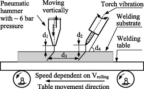
The setup of the TMW system is schematically presented in . The pneumatic hammer is made of 42CrMo4 steel with a hardness of 550 HV 10. The rectangular tip is 15 mm 2 mm. The hammer moves vertically with a free stroke of 13 ± 0.5 mm and a cycling frequency of 35 Hz at a constant air pressure of 6 bar [Citation40,Citation41]. In , four parameters, i.e. d1–d4, determine the relative positions of the hammer and welding torch with a needle. d3 is the offset between the hammer and the torch needle, that determines the point where the hammering starts after the TIG welding. The TIG arc had a specific vibration caused by the frequent hammering during TMW welding, and the amplitude depended on the hammering force.
Figure 2. Schematic diagram of TMW system with a pneumatic hammer.
The processing parameters of the TMW system are summarized in . The welding speed V (cm/min), the welding current I (A), and the parameter d3 (mm) determine the specific welding experiment. The other processing parameters were kept constant.
Table 2. Processing parameters of the TMW system in this work.
2.3. Experimental procedure
The AISI 304L plates with identical length and width dimensions (i.e. 100 mm 50 mm) were tested as follows: (a) regular TIG welding (b) TMW welding with the processing parameters and corresponding heat inputs (J/mm) listed in . The heat inputs were calculated at a unified thermal efficiency of 0.9 based on the online welding calculator developed by voestalpine [Citation42]. The lower the welding speed and/or the higher the welding current, the larger the heat inputs for the TIG bead-on-plate welding. The cooling time t8/5 was calculated using the procedure shown in Appendix II and listed in .
Table 3. Processing parameters and the related heat inputs (J/mm) of the TMW and TIG welding experiments on the AISI-304L ASSs.
Standard metallographic techniques were used to analyze the microstructure of the performed samples [Citation2]. Two samples were extracted from each weld as shown in to evaluate their microstructure. The samples were electrolytically etched by a solution containing 60% nitric acid and 40% distilled water [Citation2,Citation43]. The microstructure of welds was captured using a light optical microscope (Zeiss Observer Z1m with an Axio-Cam-MRC5 camera). The macro images of welds were captured by a macro observing system with a camera (Nikon-N90). The three geometric attributes of the FZ, i.e. semi-width (W), depth (D), and semi-area (A) (), were obtained from the macro images. The mean grain size within the HAZ was measured in the green region at the cross-section of the sample, and the data were calculated by image processing using ImageJ analysis.
Figure 3. 3D schematic diagram of the TIG bead-on-plate semi-weld with dimensions: A—semi area, W—semi width, and D—depth of the FZ observed at the cross-section. In addition, the red arrow indicates the TIG welding trajectory.
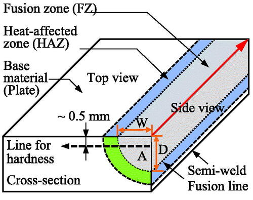
The content of the ferromagnetic phase was determined from the top surface of welds with the ferritscope-FMP30 (produced by company Fischer). According to the standard procedures [Citation2,Citation31,Citation44], five measurements with a 10 mm interval along each weld were carried out to calculate the mean value. Finally, the mechanical property of welds was determined by Vickers hardness (HV 0.3) along the cross-section of welds. Line measurements were performed to evaluate the hardness distribution from the FZ to the base material. The line is parallel to the top surface of welds with an approximate 0.5 mm interval, as shown in .
3. Results and discussion
There are two kinds of vibration acting on the weld during the TMW: (a) the mechanical vibration by frequent hammering on the cooling weld, and (b) the TIG arc vibration on the liquid weld by the vibrated torch (seen in ). These coupled vibrations influence the phase and microstructure evolutions of the FZ. The effect of plastic deformation on the microstructure refinement is also analyzed.
3.1. Influence of heat input on the weld size and phase content
3.1.1. Dimensions of the FZ
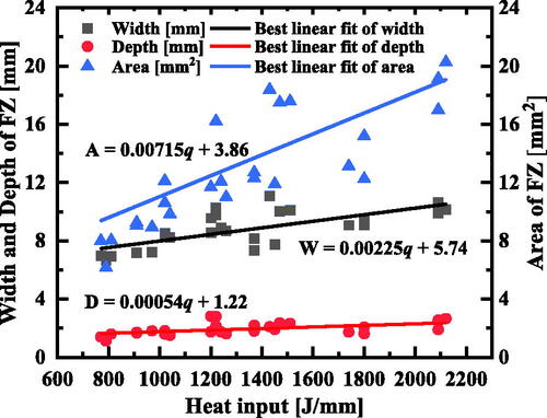
shows the evolution of the dimensions of the FZ of TIG bead-on-plate welds by varying heat input (q). The width W (mm), depth D (mm), and area A (mm2) of the FZ present a more or less linear trend with respect to the heat input. Evidently, the heat input q is a function of the welding current, voltage and speed for the TIG bead-on-plate welding [seen in EquationEquation (A-1(1)
(1) ) in Appendix II]. EquationEquation (1)
(1)
(1) indicates the relationship between the dimensions (described by f(U, I, V)) of the FZ and the parameters of TIG bead-on-plate welding and shows that the lower welding speed and/or the larger welding current, the higher heat input and thus the larger size of the FZ.
(1)
(1)
where
is a constant,
and
are fitting parameters for the depth, width, and area of the FZ observed at the cross-section of welds.
Figure 4. Evolution of the FZ dimensions (i.e. width-W, depth-D, and area-A at the cross-section) of TIG bead-on-plate welds of the AISI 304L ASS to heat inputs.
3.1.2. Ferromagnetic phase content of the FZ
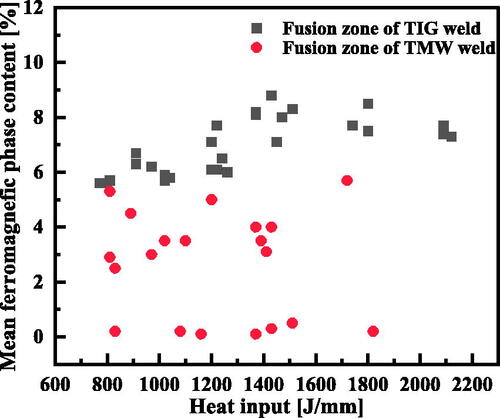
shows the mean ferromagnetic phase contents (abbreviated with MFPC) in the FZ of both TIG and TMW welds at various heat inputs. It can be seen that the MFPC of TMW welds is systematically smaller than that of TIG welds. In this work, the AISI 304L welds have a moderate Creq/Nieq ratio (∼1.86 calculated by Hammer’s equivalents [Citation45]), indicating that these studied welds were solidified in the FA mode (within the Creq/Nieq ratio range of 1.48–1.95 [Citation5,Citation6]) at normal TIG welding conditions. However, during the TMW welding, the frequent vibration of the TIG arc caused by the hammering broke the primary dendritic δ-ferrite, retarding its growth due to the deviation of preferential direction <100 > [Citation6,Citation7]. This phenomenon reduced the δ-ferrite content in TMW welds. In addition, the distribution of phases is relatively more homogeneous due to the stirring of the weld pool by the frequent vibrations.
Figure 5. Comparasion of the mean ferromagnetic phases content between the TIG and TMW welds of the AISI 304L ASS at various heat inputs at the FZ.
3.2. Influence of frequent hammering on the microstructure of TMW welds
shows the macro-pictures of TIG and TMW (with 20 mm offset) welds for CR25 plates at identical TIG welding conditions. Both welds are clarified into three regions according to the microstructures: (a) FZ (FZ), (b) HAZ (outlined by black dash lines), and (c) base material (BM) of CR25 AISI 304L ASSs. The significant difference in FZ morphology is that the FZ top region becomes flatting during the TMW due to frequent hammering. However, the microstructure of FZ is totally different, as observed in .
Figure 6. Low magnified LOM images of two different bead-on-plate welds of cold-rolled AISI 304L with 25% thickness reduction: (a) a TIG weld and (b) a TMW weld obtained with 20 mm offset at a constant TIG welding current of 150 A, and welding speed of 12 cm/min.
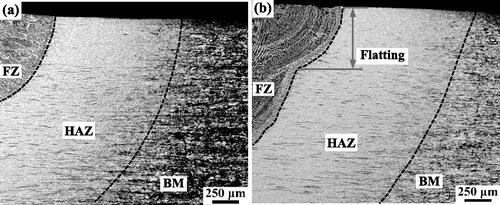
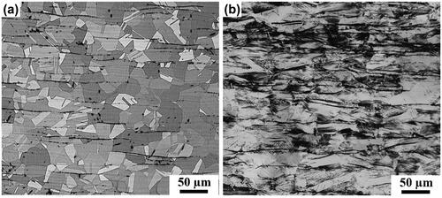
Figure 7. LOM images of the FZ and HAZ of TIG and TMW bead-on-plate welds on the material of cold-rolled AISI 304L by 25% thickness reduction (CR25) at the constant welding current of 150 A, and welding speed of 12 cm/min, and additionally with 20 and 30 mm offsets between the TIG torch and hammer for the TMW welds. (a–c) are in FZ, and (d–f) are in the HAZ.
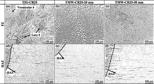
shows typical microstructures of the FZ and HAZ for both TIG and TMW welds of CR25 plates at constant TIG welding parameters of 150 A and 12 cm/min. show the coarser microstructure of the FZ for the TIG welds than for TMW welds. Concerning the FA solidification mode of such welds [Citation5,Citation6], the δ-ferrite is the primary phase, and then γ-austenite solidified as the secondary phase (formed as divorced eutectic [Citation7]). In , two types of δ-ferrite morphology in the TIG welds are observed: one is known as ‘vermicular,’ and the other is ‘lacy.’ When performing the TMW welding, the TIG arc and mechanical vibrations refined the solidified microstructures of welds, characterized by numerous vermicular δ-ferrite with various thicknesses, as shown in . These different microstructures of FZ are adcribed to the given distinct offsets (i.e. 20 and 30 mm, respectively). The offset determines the deformation temperature as starting frequent hammering: the larger the offset, the smaller deformation temperature. The temperature plays an important rolea on the plastic deformation. The mechanical vibration on the solidifying microstructure due to the frequent hammering lead to different cooling conditions and kinetics of phase transformation (i.e. FA mode solidification), and finally result in the distinct microstructure evolutions. In addition, these vermicular δ-ferrites are usually located at the centre of solidification cells surrounded by γ-austenite.
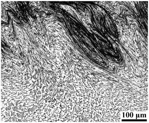
shows that grain in the HAZ of TIG and TMW welds become equiaxed cells because of the static recrystallization of the cold rolled material at high temperatures. It can be observed clearly that no apparent difference in grain size and grain morphology in the HAZ existed between the TIG and TMW welds. One point is that the plastic strain from the hammering is relatively small in the HAZ to produce any refinement by dynamic recrystallization. The plastic deformation on the top surface layer (0.3–0.5 mm thickness) of FZ observed in shows that there is extensive flow localization, resulting in significant microstructure heterogeneity.
Figure 8. Large heterogeneous microstructure of TMW bead-on-plate weld top region (side view of FZ) of the cold-rolled AISI 304L subjected to a 25% thickness reduction (CR25) at a welding current of 150 A, a welding speed of 12 cm/min, and an offset of 30 mm.
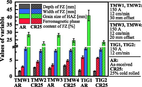
shows that the depth of FZ is larger for TMW welds with 20 mm offset than that with 30 mm offset since the smaller the hammering offset is, the higher temperature of the weld when starting the hammering. Generally, the FZ depth of TMW welds is relatively larger than that of TIG welds, ascribed to the effect of TIG arc vibration during hammering. In addition, the width of FZ is similar for all welds. However, the mean grain size of HAZ and the MFPC of FZ is larger for TIG welds than that of TMW welds, consistent with the findings in Sections Dimensions of the FZ and Ferromagnetic phase content of the FZ.
Figure 9. Comparasion of the width, depth, and mean ferromagnetic phase content in the FZ and mean grain size of HAZ of both TIG welds and TMW welds of the AISI 304L ASS at different processing conditions.
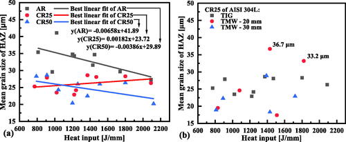
shows the mean grain size at the HAZ of AR, CR25, and CR50 AISI 304L plates at various heat inputs. The grains are larger in the HAZ of the TIG weld of AR (27.3–41.1 µm) than that of the CR25 (22.9–28.6 µm) and CR50 (20.2–28.6 µm), as plotted in . Martensite reversion transformation and static recrystallization (SRX) takes part in the HAZ of the cold-rolled plates and refines the grains [Citation46,Citation47]. Similar to the linear fitting of FZ dimensions to heat input [seen in and EquationEquation (1)](1)
(1) , the best linear fitted plots of the mean grain size of HAZ to the heat input and correlated equations are shown in . It can be seen that the mean grain size of HAZ of the CR25 welds roughly increases as increasing the heat input. In addition to the static recrystallization, annealing twins and martensite reversion (i.e. α′ → γ and/or ε → γ [Citation48]) take place. Therefore, there is a significant difference for the cold-rolled AISI 304L plates with distinct thickness reductions in the final microstructure. comparatively shows the mean grain size of the HAZ between TMW welds and TIG welds of CR25 plates at various heat inputs. It can be seen that a more considerable fluctuation of the mean grain size of HAZ occurs in the TMW weld than in the TIG weld. For instance, two significantly large mean grain sizes, viz., 33.2 and 36.7 µm, were observed for the TMW welds with a 20 mm offset when the heat input >1400 J/mm. Such irregular deviations are generally ascribed to the occurrence of secondary recrystallization. The competitive microstructure changes, including the martensite reversion transformation, static recovery, static recrystallization, secondary recrystallization, and occurrence of annealing twins, highly depend on the heat input. Their interactions and occurring sequence result in the distributions of mean grain size, shown in . Briefly, the hammering indirectly influenced the heat input, leading to the different thermal effects on the microstructure evolution of HAZ and finally resulting in various mean grain sizes.
Figure 10. Mean grain size of the HAZ in TIG and TMW welds: (a) TIG welds at different initial material states, and (b) in the TMW welds of CR25 AISI 304L at various heat inputs.
3.3. Influence of hammering on the mechanical property of TMW welds
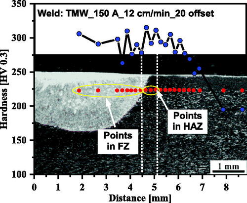
shows the hardness (HV 0.3) distribution of the TMW weld from the FZ to HAZ and further to the base material. This TMW welding was carried out on the AR plate at the welding current of 150 A and welding speed of 12 cm/min with a 20 mm offset between the hammer and welding torch. The higher hardness is in the FZ and HAZ close to the fusion line due to the formation of fine microstructures and somehow strain hardening by hammering, which decreases gradually to the bottom at the base material of the AR plate. To get the mean value of hardness in the FZ and HAZ at different welding conditions, all points in FZ and the first four points in HAZ (i.e. the regions covered by yellow ellipses in ) for each sample were selected to do data analysis.
Figure 11. Hardness profiles of the TMW weld of as-received AISI 304L at a welding current of 150 A, a welding speed of 12 cm/min, and a 20 mm offset between the hammer and TIG torch.
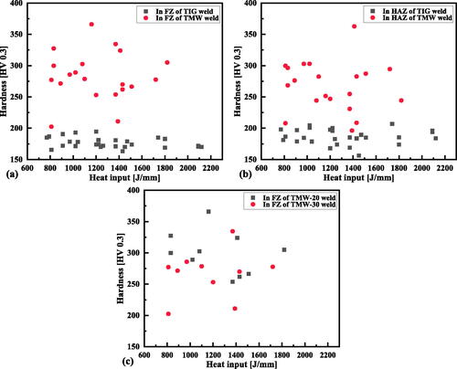
shows the mean hardness in FZ and HAZ of both TIG and TMW welds at various heat inputs. Firstly, the hardness is apparently larger in the FZ and also HAZ of TMW welds than that of the TIG welds, as shown in , respectively. Meanwhile, the hardness distribution is correlated with the microstructure state, as evidenced in . The influence of hammering offset on the hardness of FZ can be seen in . Roughly concluded, the larger hammering offset of TMW welding and the smaller FZ hardness is due to the smaller plastic strain and low temperature when starting the hammering. The deviation is ascribed to the competitive behaviour of the strain hardening and the microstructure recrystallization during hammering. To sum up, the mechanical property of TMW welds is relatively enhanced than that of TIG welds.
Figure 12. Comparasion of the hardness in the TIG and TMW welds of ASS AISI 304L to heat inputs for different positions of welds (a) FZ, (b) HAZ, and (c) for different offsets of the TMW welding.
4. Summary and conclusions
The TIG and TMW were conducted on the as-received and cold-rolled (with 25% and 50% thickness reduction) AISI 304L plates over a welding current range of 125–175 A and a welding speed range of 7–12 cm/min. The TMW process was composed of TIG welding and subsequent hammering. Plastic deformation was carried out on the cooling TIG weld using frequent hammering with a 20 or 30 mm offset between the TIG torch and hammer. The dimensions (i.e. width, depth, and area) and ferromagnetic phase content of the FZ, the mean grain size of the HAZ, hardness (HV 0.3) distribution of TIG and TMW welds, and the related microstructure were compared to analyze the effect of hammering and vibration on the microstructure and mechanical property of welds. Static recrystallization (SRX) in HAZ and δ-ferrite morphology in FZ were discussed. Several conclusions are summarized as follows,
(a) Two types of vibrations occurred during the TMW welds due to frequent hammering: one is TIG arc vibration, and the other is the mechanical vibration of the sheet. Both vibrations broke the dendritic δ-ferrite during the solidification of the FZ. The FZ is characterized by numerous fine vermicular δ-ferrite compared to coarse lacy δ-ferrite observed in TIG welds. The severe plastic deformation observed on the top surface layer of FZ produced a largely heterogeneous microstructure. In addition, the TIG arc vibration enlarged the depth of FZ.
(b) Ferromagnetic phase content of FZ in TMW welds is smaller than that in TIG welds. The frequent hammering fragmented the dendritic δ-ferrite and retarded its growth due to deviation of preferential growth direction.
(c) The hammering has a minor influence on the grain size evolution of HAZ because of the neglected plastic strain on that region. The mean grain size of HAZ is usually smaller for welds of the cold-rolled than as-received AISI 304L plates since martensite reversion and SRX occurred in the cold-rolled plate rather than the single grain growth in the as-received plate.
Several aspects has to be clearified for TMW welding: (a) the influence of single mechanical vibration on the microstructure refinement of FZ, (b) the effect of more extensive plastic deformation on FZ by decreasing the hammer length (approximately equals to the width of FZ) to investigate the dynamic recrystallization of AISI 304L welds.
Acknowledgments
The authors carried out this work under the project of FWF Project in Austria– Thermomechanical welding (No. 16732).
Disclosure statement
No potential conflict of interest was reported by the authors.
References
- Lo KH, Shek CH, Lai JKL. Recent developments in stainless steels. Mater Sci Eng R-Rep. 2009;65(4–6):39–104.
- Szałowski B. Effect of thermomechanical welding on the austenitic stainless steel [master’s thesis]. Austria: Graz University of Technology; 2022.
- Sutton BJ. Development of a primary solidification mode diagram for austenitic stainless steel weld metals using CALPHAD-based modeling [dissertation]. America: The Ohio State University; 2021.
- Li LC, Chai MY, Li YQ, et al. Effect of welding heat input on grain size and microstructure of 316L stainless steel welded joint. AMM. 2013;331:578–582.
- Suutala N, Takalo T, Moisio T. Ferritic-austenitic solidification mode in austenitic stainless steel welds. MTA. 1980;11(5):717–725.
- Inoue H, Koseki T. Solidification mechanism of austenitic stainless steels solidified with primary ferrite. Acta Mater. 2017;124:430–436.
- Inoue H, Koseki T. Clarification of solidification behaviors in austenitic stainless steels based on welding process. Nippon Steel Tech Rep. 2007;95:62–70.
- Osamu K, Kazuo K, Yasushi K. Effects of δ-ferrite morphology on low temperature fracture toughness of austenitic stainless steel weld metal. Weld Int. 1992;6(8):606–611.
- Inoue H, Koseki T, Ohkita S, et al. Formation mechanism of vermicular and lacy ferrite in austenitic stainless steel weld metals. Sci Technol Weld Join. 2000;5(6):385–396.
- Naghizadeh M, Mirzadeh H. Effects of grain size on mechanical properties and Work-Hardening behavior of AISI 304 austenitic stainless steel. Steel Res Int. 2019;90(10):1900153.
- Morris JW. Jr., The influence of grain size on the mechanical properties of steel. OSTI.GOV Technical Rep.; 2001.
- Wang P, Zhao J, Ma L, et al. Effect of grain ultra-refinement on microstructure, tensile property, and corrosion behavior of low alloy steel. Mater Charact. 2021;179:111385.
- Poddar D, Chakraborty A, B RK. Annealing twin evolution in the grain-growth stagnant austenitic stainless steel microstructure. Mater Charact. 2019;155:109791.
- Sadeghi F, Zargar T, Kim JW, et al. Role of the annealing twin boundary on the athermal α′-martensite formation in a 304 austenitic stainless steel. Materialia. 2021;20:101218.
- Jin Y, Bernacki M, Rohrer GS, et al. Formation of annealing twins during recrystallization and grain growth in 304L austenitic stainless steel. MSF. 2013;753:113–116.
- Wen T, Liu SY, Chen S, et al. Influence of high frequency vibration on microstructure and mechanical properties of TIG welding joints of AZ31 magnesium alloy. Trans Nonferrous Met Soc China. 2015;25(2):397–404.
- Sabzi M, Dezfuli SM. Drastic improvement in mechanical properties and weldability of 316L stainless steel weld joints by using electromagnetic vibration during GTAW process. J Manuf Process. 2018;33:74–85.
- Ma C, Li CL, Yan YH, et al. Investigation of in situ vibration during wire and arc additive manufacturing. 3D Print Addit Manuf. 2021. DOI:10.1089/3dp.2021.0053
- Al-Qawabah SMO, Zaid AI. Different methods for grain refinement of materials. Int J Sci Res. 2016;7(7):1133–1140.
- Dehghan-Manshadi A, Barnett MR, Hodgson PD. Hot deformation and recrystallization of austenitic stainless steel: part I. Metall Mat Trans A. 2008;39(6):1359–1370.
- Dehghan-Manshadi A, Barnett MR, Hodgson PD. Hot deformation and recrystallization of austenitic stainless steel: part II. Metall Mat Trans A. 2008;39(6):1371–1381.
- Dehghan-Manshadi A, Barnett MR, Hodgson PD. Recrystallization in AISI 304 austenitic stainless steel during and after hot deformation. Mater Sci Eng A. 2008;485(1–2):664–672.
- Sarkar Jkc A. Investigation of progress in dynamic recrystallization in two austenitic stainless steels exhibiting flow softening. Int J Met Eng. 2013;2(2):130–136.
- Jozaghi T, Samimi P, Chumlyakov Y, et al. Role of thermally-stable deformation twins on the high-temperature mechanical response of an austenitic stainless steel. Mater Sci Eng A. 2022;845:143199.
- Wang CH, Sun CY, Cai W, et al. Evolution of partial dislocation slip-mediated deformation twins in single crystals: a discrete dislocation plasticity model and an analytical approach. Int J Plast. 2022;152:103230.
- De AK, Speer JG, Matlock DK, et al. Deformation-induced phase transformation and strain hardening in type 304 austenitic stainless steel. Metall Mat Trans A. 2006;37(6):1875–1886.
- Naghizadeh M, Mirzadeh H. Microstructural evolutions during annealing of plastically deformed AISI 304 austenitic stainless steel: martensite reversion, grain refinement, recrystallization, and grain growth. Metall Mat Trans A. 2016;47(8):4210–4216.
- Padilha AF, Lesley RL, Rios PR. Annealing of cold-worked austenitic stainless steels. Isij Int. 2003;43(2):135–143.
- Kheiri S, Mirzadeh H, Naghizadeh M. Tailoring the microstructure and mechanical properties of AISI 316L austenitic stainless steel via cold rolling and reversion annealing. Mater Sci Eng A. 2019;759:90–96.
- Paggi A, Angella G, Donnini R. Strain induced grain boundary migration effects on grain growth of an austenitic stainless steel during static and metadynamic recrystallization. Mater Charact. 2015;107:174–181.
- Siddiqui MF. Recrystallization and grain growth behavior of austenitic stainless steel 304L [master’s thesis]. Austria: Graz University of Technology; 2021.
- Naghizadeh M, Mirzadeh H. Recrystallization and grain growth upon annealing of cold worked austenitic stainless steels [book: recrystallization: types, techniques and applications]. New York: Nova Science Publishers, Inc.; 2020. p. 97–116.
- Shirdel M, Mirzadeh H, Parsa H. M. Microstructural evolution during normal/abnormal grain growth in austenitic stainless steel. Metall Mat Trans A. 2014;45(11):5185–5193.
- Padilha AF, Dutra JC, Randle V. Interaction between precipitation, normal grain growth, and secondary recrystallisation in austenitic stainless steel containing particles. Mater Sci Technol. 1999;15(9):1009–1014.
- Randle V, Brown A. Development of grain misorientation texture, in terms of coincident site lattice structures, as a function of thermomechanical treatments. Philos Mag A. 1989;59(5):1075–1089.
- McGuire FM. Stainless steels for design engineers. USA: ASM International, Materials Park; 2008.
- Hedström P. Deformation induced martensitic transformation of metastable stainless steel AISI 301 [dissertation]. Sweden: Luleå University of Technology. 2005.
- Sohrabi MJ, Naghizadeh M, Mirzadeh H. Deformation-induced martensite in austenitic stainless steels: a review. Arch Civ Mech Eng. 2020;20:124.
- De AK, Murdock DC, Mataya MC, et al. Quantitative measurement of deformation-induced martensite in 304 stainless steel by X-ray diffraction. Scr Mater. 2004;50(12):1445–1449.
- Azkue JE. In-situ analysis of thermomechanical welding process [bachelor’s thesis]: Spain: Mondragon University Faculty of Engineering. 2022.
- Mayer T. Einfluss des thermomechanischen Schweißens auf einen austenitischen Zusatzwerkstoff [dissertation]. Austria: Graz University of Technology. 2017.
- Welding VB. Welding calculator, Available from: https://www.voestalpine.com/welding/Services/weldNet-Software-Solutions/Welding-alculator2.
- Baghdadchi A, Hosseini VA, Karlsson L. Identification and quantification of martensite in ferritic-austenitic stainless steels and welds. J Mater Res Technol. 2021;15:3610–3621.
- NUSATEK. Ferrite Content Measurement (Ferritescope Test). Available from: http://www.nusatek.com/on-site-material-inspection/ferrite-content-measurement-ferritescope-test.html.
- Suutala N. Effect of manganese and nitrogen on the solidification mode in austenitic stainless steel welds. MTA. 1982;13(12):2121–2130.
- Odnobokova M, Belyakov A, Enikeev N, et al. Annealing behavior of a 304L stainless steel processed by large strain cold and warm rolling. Mater Sci Eng A. 2017;689:370–383.
- Tikhonova M, Belyakov A, Kaibyshev R. Static grain growth in an austenitic stainless steel subjected to intense plastic straining. Adv Mat Res. 2014;783:1021–1026.
- Alves J, Brandao LP, Paula A. Mechanically induced martensitic transformation of hot rolled and annealed 304L austenitic stainless steel at room and cryogenic temperatures. Mat Res. 2019;22(suppl. 1):e20190150.
Appendix I
shows the microstructure of as-received and cold-rolled with 25% thickness reduction (CR25) of AISI 304L plates at initial conditions. These two samples were immersed in etching by Beraha’s tint etch. This etchant comprises one part HCL, two parts H2O, and 1 g K2S2O5 per 100 mL solution, which can reveal the δ-ferrite and DIM phases. (a) shows the black δ-ferrite and prior γ-austenite grains with twins. The DIM in the CR25 plate is characterized by black colour, and the correlated morphology is shown in (b).
Figure A-1. LOM observations (photographed in black and white) of the as-received (a) and cold-rolled with 25% thickness reduction (b) of AISI 304L ASS at initial conditions.
Appendix II
Table A-1. The calculated time t8/5 (s) of performed TMW and TIG welding tests on the ASS AISI-304L
Heat input by TIG bead-on-plate welding is a function of welding parameters formulated in Equation (A-1). In addition, this equation is utilized on the same thickness of the plate.
(A-1)
(A-1)
where q is heat input (J/mm), U is welding voltage (V), I is welding current (A), V is welding speed (cm/min) of TIG bead-on-plate welding, and
is the related thermal efficiency, and 0.9 is selected in work. The cooling time t8/5 is used to evaluate the colliding rate of a weld bead and its corresponding HAZ to pass through the temperature range from 800 °C to 500 °C. The t8/5 of performed TIG and TMW welding experiments were all listed in , which was calculated by the online welding calculator developed by Voestalpine [Citation42].