
Abstract
Different kinds of design structure are created and used in engineering design and development processes. Function structures, design grammars and bills of materials are common examples. However, there is a lack of clarity regarding distinctions and similarities between different kinds of structure and systematic ways to articulate them. This paper brings together research on product structuring and shape computation to inform the specification of principles for the definition of design structures. The principles draw together findings reported in the computational geometry and product definition literature with research from a range of companies and industry sectors that encompasses enterprise and process structures. The potential value of the principles to computer-integrated manufacturing and through-life support is demonstrated through application to four case studies.
Introduction
Engineering design is an important early stage of the innovation processes that deliver new products to markets where societal challenges are addressed and wealth generated. High-quality engineering design information is critical to the effective and efficient manufacture, production and through-life support of such products. The emerging discipline of engineering design informatics brings together ICT (Information and Communications Technology) and engineering design to support the creation of well-founded engineering information support systems. However the current state-of-the-art is characterised by experience-based frameworks and approaches from engineering design coupled with general purpose ICT frameworks (such as SYSML) which provide wide-ranging functionalities but require substantial effort and scarce expertise to create even demonstrator solutions. These problems can be attributed, in part, to shortcomings in the cognate body of knowledge that underpins the discipline of engineering design which result in slow incremental progress based on a series of ad hoc solutions with few if any high-impact breakthroughs. The importance of the discipline of engineering design informatics is growing for CIM because digital information is becoming a key input to and platform for manufacturing systems. These systems have a direct impact on the effectiveness and efficiency of manufacturing operations and, as a result, deficiencies in the information that drive them are likely to become a limiting factor in system performance. In addition, design information provides new opportunities as a critical underpinning to enable the closing of loops between manufacturing and design, so offering the potential for design to be better informed by manufacturing practices and experiences.
The goal of this paper is to contribute requirements for an underlying theoretical framework for the representation and structuring of design and manufacturing information that will address these issues and contribute to the creation of affordable, efficient and effective ways to support engineering products through life. This is especially challenging because the lives of many products are expected to extend beyond the working lives of the engineering designers who created them, and design information is often inaccessible because it has embedded within it idiosyncrasies of the people who created the design or the computational systems they used. Benefits would include a well-founded theoretical and computational infrastructure on which the next generation of design, manufacturing and lifecycle support systems could be built. The novel contribution of this paper is the development of six principles for the definition of design structures and a template-based method that has been used to operationalise the application of the principles to case-study design structures.
This paper proposes a collection of six principles for the definition of design structures. It begins with a review of literature on design structures and their application in engineering product development processes. This is followed by a description of the research methodology used to develop the principles and a section outlining the principles themselves. Building on these principles, a template for their application to engineering problems is proposed and used to validate the principles through application to four case studies. The case studies cover a range of design and manufacturing process stages and associated design structures. Learning from across these case studies is then discussed and areas for future research identified.
Background
For the purposes of this paper, engineering design processes result in definitions of physical artefacts. Engineering design deals with a special kind of physical artefact, technical artefacts, and a number of commentators discuss the dual nature (functional and physical) of such artefacts (Anon Citation2014). Like all physical artefacts, technical artefacts have two physical properties that give them their existence (potential or actual): shape and material. Today’s engineering design processes typically involve two inter-related activities: the definition of shapes (e.g., using computer-aided design systems) and the specification of materials (e.g., using software packages such as EduPack [www.grantadesign.com/]). For this paper, whilst recognising that they are interdependent, we regard shape definitions as the results of generative processes and material specifications as the results of selection processes. However, it may be useful and practicable to consider shape and material as the combined result of a generative process (Stiny Citation1991). The development of the principles introduced in this paper has also been cognizant of developments in advanced materials (such as composites) and manufacturing technologies (such as 3D printing) that promise engineering design processes where both shape and material definitions are generated together.
Definitions of shapes may be variously given and range from structured entities in which shape components are independently specified to unstructured ones in which shape components are left unresolved to be specified on the fly. In the former, set-like structures, e.g., graphs or trees that record components and their connections, may be used as representations of shapes. This facilitates generative processes, as the atoms of computation are given explicitly. Alternatively, algebras based on more general part relations or partial orders are also possible. This supports the possibility that the parts of shapes may change radically, while preserving the possibility that shapes arise in generative processes. Of course, both structured and unstructured approaches to shape definition can be related, in particular when the latter supports multiple versions of the former (Stiny Citation2006). Questions of size may be addressed in both approaches, too, when equivalence relations are defined on shapes in terms of transformations. Evidence of the logical separation between shape and size can be seen from pre-CAD engineering design practices where a given design often had multiple drawings, e.g., one for manufacturing and a different one for inspection.
A common feature of the numerous engineering design processes available in the literature is that they begin with users’ wants and needs which are translated into design requirements that drive subsequent stages of the process. Guidance on how best to derive and formulate design requirements, especially for so-called wicked problems typified by multiple users with different roles, needs and wants that interact and at times conflict with each other, is less well developed (Agouridas et al. Citation2008). In the engineering design-research community, affordance-based design is becoming established as a means of relating customer needs with design requirements (Wu, Ciavola, and Gershenson Citation2013; Booth, Reid, and Ramani Citation2013; Lewis et al. Citation2013; Li and Tate Citation2013). Given a collection of design requirements, functional requirements and structures are derived. With respect to thinking on the dual nature of technical artefacts, all of these approaches sit in a functional space imposed by people and are not intrinsic properties of the final design. For example, Cormier, Olewnik, and Lewis (Citation2013) refer to ‘Desired Affordance Models’ and functional requirements may be expressed as shape models. The aero lines that specify the flow paths of air into the nose cowl of an aero engine are a conspicuous example of this. In this paper, design goals and constraints are regarded as design requirements that arise from people and processes involved in the development of the product itself, e.g., manufacturers and, with the move to through-life support, service engineers and organisations.
At their most abstract, engineering design processes are transformation processes that convert design requirements into designs, i.e., shape definitions and associated material specifications. For all but the most trivial design activities, this conversion process includes human creativity and ingenuity that rely on design structures as sense-making devices. Many different kinds of design structure are identified in the literature but the question of precisely what is (and is not) a design structure remains unclear (Andreasen et al. Citation1997; McKay Citation1997). For example, Pahl and Beitz (Citation1999) and Dym and Little (Citation2009) identify the function and physical structures that include both breakdown structures and flows, e.g., between functions. Similarly, Cagan and Vogel (Citation2002) and Ulrich and Eppinger (Citation2008) provide examples of product structures in the context of designing. These include hierarchies of needs and product family architectures and, through product case studies, the superimposition of part names and details related to aesthetics, ergonomics and manufacturing on to shape representations (in the form of sketches) of the product.
For the purposes of this paper, design structures are artificial [sense-making] devices used to make physical artefacts (or their definitions) easier to use in engineering processes. The principles introduced in this paper build on the premise that a given design can be assigned multiple design structures, which may be of different types, e.g., function versus behaviour versus physical and/or have different purposes, e.g., engineering bill of material (BOM) versus manufacturing BOM versus service BOM. There are many examples in the literature. For example, Andreasen’s (Citation1999) chromosome model provides four different perspectives on a given design (process, function, organ and part). These are each depicted by Fan et al. (Citation2005) as four different kinds of design structure, each with its own kind of element, that can be related to other research on design structures. For example, there are direct parallels between Andreasen’s process perspective and Maier and Fadel’s (Citation2009) affordance structures. Similarly, work with the US DoD on the reconciliation of multiple BOMs (Dement et al. Citation2001) aligns with Andreasen’s parts perspectives. Dement et al. (Citation2001) is an early example of research that recognised the value of relating multiple design structures of a given kind (e.g., BOMs) to a single design. More recently, work on through-life support for engineering products, such as that in ISO 10303-239 (Citation2012), recognises the need for multiple product structure views and breakdown structures. Trott et al. (Citation1999) report on the application of a framework for the characterisation of product (functional and physical) structures to aero engines which provided an example of the potential value to be gained from being able to define and relate multiple structures for a given design – in particular, the nose cowl of an aero engine – in a systematic manner. The purpose of assigning structures is to support design-related activities. For example, in Trott et al. (Citation1999), functional and physical structures were specified along with relationships between them; this allowed users to answer questions such as, ‘Given a change in the functional requirements of the aero engine, how long will it take to modify the design and deliver products to the new design?’ This was a real world problem, initiated by changes in the operating cycles of the airlines that operated the planes containing the engine. The value of the pair of related design structures was that, given an appropriate definition, engineers could identify the parts in the physical structure that were affected by changes to the functional structure. The application of these ideas was not developed beyond the paper because the cost (measured in the time needed from already overloaded product development engineers working to demanding schedules) involved in specifying and verifying the necessary structures and interrelationships was deemed to be unaffordable. The long-term goal of the thinking introduced in this paper is to provide underlying formalisms for the systematic specification of design structures, which, like solid modelling formalisms that underpin contemporary shape design systems, both improve the efficiency with which design structures are specified and provide opportunities for the development of applications to support and improve (measured in the time needed from practitioners, accuracy and repeatability) the validation and verification of given design structures.
Once defined, there are numerous methods intended to support design processes using design structures, e.g., as evidenced by interest in Dependency and Structure Modelling (www.dsm-conference.org/dsm2014.html) and Design Structure Matrix-based approaches (Steward Citation1981; Borjesson and Sellgren Citation2013). There has been less work on systematic approaches to the definition of the design structures that feed into these approaches. For example, Booth, Reid, and Ramani (Citation2013) highlight difficulties in diagramming methods. Alternatively, the rules in generative design systems may be regarded as a form of design structure, where the arcs between rules record the sequence of transformations from one design to another. With respect to design structuring, many researchers report results of work that, given one or more design structures, can be used to gain insights (e.g., see the Dependency & Structure Modelling series of conferences for applications [www.dsm-conference.org/]) and improve engineering design activities. However, there is less emphasis on the problem of how design structures might be defined in the first place and well-founded underpinnings for such definitions. This is the focus of this paper, specifically, a contribution to requirements for theoretical underpinnings that might be a part of the cognate discipline of design structuring in the context of engineering design. Making these principles explicit is an important step to establishing usable design theories and may well lead to increased uptake of DSM and similar methods by making the definition of design structures more routine and systematic. The principles themselves are currently expressed in natural language. The possibility for a rigorous mathematical (algebraic) formulation remains open but real.
Methodology
The principles introduced in this paper were developed using an abductive research process (Dubois and Gadde Citation2002) built on cases drawn from collaborative industry-linked research activities and participation in European and US discussions on engineering design for over 15 years. Key aspects of the methodology used in this research are shown in . The focus of this paper is the principles and their validation.
Figure 1. Methodology.
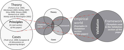
An early framework for the characterisation of product structures was published in McKay (Citation1997). This framework, derived from and developed through discussions at the WDK workshop series on product structuring (Tichem et al. Citation1995; Mortensen Citation2003), was applied to aero product (functional and physical) structures in Trott et al. (Citation1999). Learning from this work was coupled with thinking on shape computation (Stiny Citation2006) and mereology (Simons Citation2000; Dement et al. Citation2001) in the establishment of a representation scheme for what, in this paper, we refer to as ‘design structures’ (McKay and de Pennington Citation2001). The focus of this paper is on the principles themselves (see next section) and their validation through application to examples taken from what Dubois and Gadde refer to as the ‘empirical world’. The validation process required a research instrument that could be used to apply the principles to examples with minimal noise such as the additional constructs that often arise from computer implementation. The research instrument, in the form of a template for the application of the principles, and its application to examples are introduced after the next section, which details the principles themselves.
Principles for the definition of design structures
The principles introduced in this section were established to address the problem, evidenced in the Background section, that digital design definitions frequently include multiple, often incomplete, design structures. The lack of clarity and potential for discrepancies that results from these structures being superimposed on each other prevents progress and makes design structuring a heuristic, and so difficult to repeat, process. A repeatable process that the implementation of such principles might underpin, can clarify, e.g., what is being represented, where shape might come in and in what form, and omissions in the design definition. For example, shape is a core part of the definition of a physical product. However, it can also be used in other ways in a design definition. For example, shapes can be used to represent functional units (that are connected in circuit diagrams that can be regarded as a form of functional model) before a shape has been conceived or to illustrate the intended use of a part. There are six principles in total. The first two principles introduce the distinction between shape and material (constitution in Dement et al., Citation2001) that are consequences of the physical existence of technical artefacts, and design structures that are artificial devices created by people to support sense-making. As such, there is no physical restriction on the number of structures that might be associated with a given technical artefact.
Principle 1:
A given physical artefact, of which technical artefacts are a kind, has two intrinsic properties: shape and material.
Principle 2:
A given design may have multiple design structures.
A common feature of design structures is that they are set-like, presented as trees or graphs (hierarchies, networks and directed graphs) composed of nodes and arcs. McKay (Citation1997) was based on an analysis of papers in the previous two workshops in the WDK series. The next two principles are derived from McKay (Citation1997); in that a given design structure has two key features:Elements of a kind (e.g., the nodes in a graph diagram)
Relationships of a kind (e.g., the arcs in the graph diagram)
Principle 3:
A given design structure is composed of elements of a kind and relationships of a kind.
To apply Principle 3, users need to know the possible kinds of element and relationship. In the design of physical artefacts, the main focus of mechanical design, common kinds of element are parts (which are themselves artefacts) and functions. The specific kind of element depends on the purpose for which the design structure has been created. However, only two kinds of relationship have been identified to date. This leads to the fourth principle.Principle 4:
The relationships in a given design structure are one of two types: composition or connection.
Simons (Citation2000) introduces mereology, a branch of philosophy related to part-whole relationships, and its application to BOMs. Part-whole (or decomposition) relationships occur in a range of design structures, cf. Ma and Kremer (Citation2013) and Chiriac et al. (Citation2011). For example, functional decomposition structures are design structures where the elements are functions related through part-whole relationships. It is interesting to note, too, that part-whole relationships apply to the definition of shape itself, although possibly with some diversion from mereological orthodoxy to ensure, e.g., finiteness of shapes and operations, and algebraic closure (Stiny Citation2006).The other kind of relationship is a connection relationship. Assembly structures in computer-aided design systems are a common example where parts in an assembly are related to each other by assembly mating relationships that define geometric constraints between parts. Connection relationships also occur in other design structures, e.g., energy, material and information flows in a function structure. A key difference to composition relationships is that the definition of connection relationships often requires an ability to refer to elements of the things being related. For example, defining assembly mating conditions between parts requires the ability to refer to shape elements such as surfaces and centre lines. Embedding and its extension to part relations, together with boundary operators, enable the definition of these conditions (Stiny Citation2006). Connection relationships may also depend on the applications that use them. For example, solid modelling systems that use assembly-mating conditions in exploded assembly drawings can influence how connection relationships are defined. Moreover, in applications where rigidity is an assumption, connection relationships between shape elements are often constrained to occur only between siblings in a BOM. This preserves the rigidity assumption and laws of physics, where a physical part cannot be a part of itself. It further allows shape definitions to be validated syntactically, rather than through compositional analysis, which may be a far more onerous task.
Principles 3 and 4 support the specification of a given design structure but do not enable one to differentiate between design structures that have the same kinds of elements and relationships, e.g., different kinds of BOM or different BOMs for a given product that contain data at different levels of detail. This leads to the fifth principle.
Principle 5: A given design structure has a purpose for which it was created, which determines the kinds of relationship and element that are needed.
The purpose may not be clearly defined, but design structures are created with at least some purpose in the minds of their creators. McKay (Citation1997) provides elements of a purpose but ultimately the purposes are free-form text and, therefore, at high risk of ambiguity. But this risk may be worth taking to foster creativity, without the cost of a formal or algebraic approach to design structure. The Discussion section in this paper considers future possible developments in this area.The final principle ensures that both elements and relationships have equal precedence in a given structure. Our experience says that neither should have automatic precedence. For example, a BOM, and other decomposition structures, usually start with the thing being decomposed – which is an element. However, there are many examples of design structures containing connection relationships that begin with a relationship, e.g., many process models start with a flow. The final principle accommodates this requirement.
Principle 6:
In a given design structure, both elements and relationships are equal.
In addition to allowing a given structure to start and finish with both elements and relationships, this principle is important in the development of design support tools because both elements and relationships can exist independently of each other and therefore support reuse.A template for the definition of design structures
The value of templates and principles for any activity, including design structuring, lies in their potential to support the replication and transfer of knowledge (e.g., from design to manufacture) (Wæhrens, Cheng, and Madsen Citation2012). Replication of design information is important for manufacturing because without it manufacturing operations have to devote resources to dealing with special cases arising from nuances in the practices of individual designers (which tend to add cost to manufacturing) rather than in the design itself (which tend to add value to the manufactured product). The principles in this paper come from research on the establishment of high-quality digital engineering product definitions. There is a wide literature, including international standards, on underlying representation schemes (in the form of meta-models and ontologies) for the definition of product data. Digital product definitions are defined as instances of such representation schemes. For digital product definitions to be effective and efficient (defined by Wæhrens et al. as understandable, useful, and fast and affordable to use), there is a need to ensure the quality of instance data. This is a particular challenge when underlying representation schemes are generic, which is a key to effective and efficient implementation of meta-models but can compromise the effectiveness and efficiency of instances because the meta-model is less constraining on users. This issue in the reliability of computational models is detailed by Szabó (Citation1993). When considered in the context of design information, the challenge is to achieve a balance between specific models (that are easier to prove and use, but larger and so more costly to develop, maintain and build interfaces with) and generic models (that are more prone to issues associated with poor quality data highlighted by Szabó and often criticised as being vague, but are significantly less costly to develop, maintain and interface with). The template proposed in this section is directed towards addressing these issues by providing a means of using the principles introduced earlier to create high-quality digital design definitions.
The template illustrated in embodies all six principles. In this paper, it is used to validate the principles by supporting their application to case studies in the next section. The rationale for key features of the template is given in . Principles 1–4 have been taught to first year mechanical engineering and product design students as part of product dissection classes for over 10 years (Lewis et al. Citation2013). contains the content of the three slides that have been successfully used for this purpose. These slides are used in this paper to demonstrate how the template has been used to validate the principles through the definition of example design structures. It can be seen that they are based on the right-hand side of the template given in with the basic principles of design structuring covered in and the template applied to a structure containing part-whole relationships in and connection relationships in . These slides also touch on Principle 6 by not constraining the extremities of a given structure to be either an element or a relationship. A visual means of presenting Principle 5 (the purpose of a given structure) has not yet been established.
Figure 2. A template for the definition of design structures.
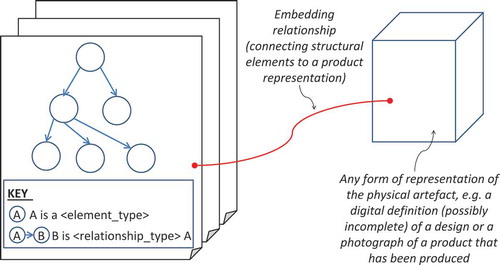
Table 1. Relationships between the principles and template.
Figure 3. The application of the template: (a) What is a product structure? (b) How to map a BOM product structure; (c) Using a product structure to carry information and mapping an assembly mating structure.
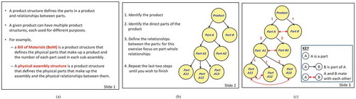
Although beyond the scope of this paper, it should be noted that both relationships and elements can be used to carry product data. For example, in many BOMs, the composition relationships have quantities assigned to them and the elements have names and part numbers associated with them for identification purposes. The precise nature of the carried data depends on the kinds of element and relationship that make up the structure and the purpose for which the structure was created. For example, shows two product structures superimposed on each other, one a BOM and the other an assembly mating structure, which would include information such as the geometric constraints between parts.
Validation of the principles
Four examples are used to demonstrate the validity of the principles. The first two relate to the use of the principles as a design development, definition & analysis tool for an existing product, the third to an established manufacturing example where different perspectives lead to the identification of different features and the fourth as a support tool for design development before a product shape has been established. Although synthetic, the examples provide an insight into the potential application and usefulness of the approach in structuring and gathering design and manufacturing information.
Use of the principles as a design development & analysis tool
In this section, the template is applied to a design development and analysis problem using Principles 1–4 and 6. The potential value of Principle 5 becomes apparent when transitioning from product dissection to the excavation, evaluation and explanation stages of product archaeology (Lewis et al. Citation2013) where parameters for the definition of purpose for a given design structure can be drawn. Although there are many papers written on the value of product archaeology to engineering education, examples that could be used in this paper are not available. For this reason, the example used in this paper is a child’s fishing game toy: primarily because it is easily accessible and highlights interesting issues for design structuring.
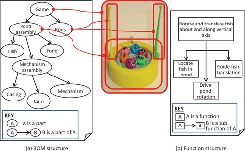
shows functional and physical structures of the game, related to a physical representation in the form of a photograph. Red lines with dotted ends show embedding relationships between the physical (BOM) structure in and the game design. For clarity, only relationships for the top two levels of decomposition are shown in the figure. Although a simple example, the fishing game highlights a number of interesting points that can be regarded as requirements for the embedding operation. Firstly, the BOM includes both integral and distributive composition relationships (Dement et al. Citation2001). For example, the two rods in the BOM are embedded into more than one discrete shape in the design and are an example of a distributive composition relationship (Dement et al. Citation2001). If a third, assembly-mating structure were added to , then each rod would need a separate instantiation to enable the definition of mating conditions that positioned each in its own hole. Another requirement for the embedding operation is highlighted through the function structure shown in . Relationships from the function structure to the game design are not shown graphically but can be inferred from the names embedded within the structure. As with the BOM in , some elements in the function structure are embedded into more than one aspect of the design. In addition, some elements of the function structure are embedded using shape elements that do not exist in the design and are themselves embedded into it. The top level function, ‘Rotate & translate fish about & along vertical axis’, is a case in point. This function refers to the fish, which are clear to see in the image and also occur in the BOM, and a vertical axis, which would be embedded into the game definition and does not appear in the BOM.
Figure 4. Application of template for the definition of physical and functional structures to a simple product.
Use of the principles as a design definition tool
In contrast to the previous section, the template is used in this section to create a collection of design definitions, often associated with different engineering disciplines, using a hydraulic car jack as an example. This product was selected because data were available for both functional and physical design structures which included both composition relationships (e.g., the BOM in ) and connection relationships (e.g., the hydraulic circuit diagram in ). Four definitions are given in . The types of design structure introduced in could, in a similar way, be defined for the car jack. This section focusses on the definition of a functional product structure with connection relationships. A number of issues arise when a design structure corresponding to the hydraulic circuit diagram in is created, as shown in . Firstly, the elements in the BOM given in ) need to be adjusted so that each part occurs in the structure the same number times it occurs in the assembly. For example, in , the check valve part appears once in the BOM with a quantity 2 to indicate that there are two occurrences in the final product. With reference to Principle 5, this is acceptable when the BOM is to be used in particular applications, such as material requirements planning where the requirement is to count parts, but if it is used to determine the parts that are to be connected to each other in the circuit diagram then the part needs to appear multiple times in the circuit structure. This is akin to the shape hierarchy created in a CAD system where, if a given part is to appear multiple times in an assembly model, each part in the assembly needs a separate occurrence.
Figure 5. Application of template for the definition of hierarchical and connection structures associated with a simple design (Image sources: schematic from http://www.antonine-education.co.uk/; jack photograph from http://www.engineeringexpert.net/).
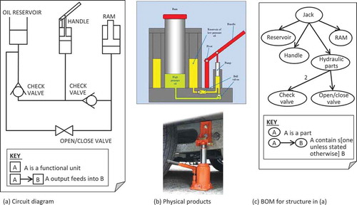
Figure 6. Design structure corresponding to the circuit diagram and BOM given in .
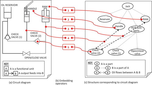
Secondly, a range of levels of detail in the circuit diagram structure are possible. In the example given in , each hydraulic component is explicitly connected to other parts; an alternative could be to connect the key functional elements of the product directly, e.g., define a connection between the ram and the handle, and define this relationship in terms of valves and other components. Applying Principle 5, the level of detail in a given structure depends on the purpose for which it is being created. Finally, for this paper, the example raises questions around relationships across functional and physical domains, which, in turn, lead to a discussion that is beyond the scope of this paper on what constitutes a function.
Use of the principles as a manufacturing development tool
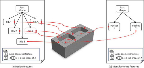
The principles were used in the previous sections to associate different kinds of structure with a given design. In this section, the principles are used to address the well-established but only partially solved problem of conflicts between design and manufacturing features. The exemplar given in is one where designers and manufacturers often use different definitions of the same shape. In this case, designers design ribs for strength and manufacturers produce ribs by machining pockets. As a result, the two design structures shown in are of the same type (i.e., elements of a type [shapes] and relationships of a type [composition]) but the data that is used to populate them is different: ribs in and pockets in . As in the fishing game example, a key challenge in implementing such structures lies in the embedding relationship, represented by the red lines, which connect elements of the design structure with aspects of the shape. However, the investment needed to achieve this is likely to be valuable because the issue of multiple perspectives on a given design is common today in manufacturing (Iacob, Popescu, and Mitrouchev Citation2012; Halfmann and Krause Citation2012) and is increasingly recognised as a problem in the support of product lifecycles where many different structures arise, not just in design and manufacturing but also through life. For example, the principles could be used to create both structures and carried data (related to both elements and relationships) to support design assembly analysis tools such as that described by Samy and ElMaraghy (Citation2010).
Figure 7. Application of template for the definition of manufacturing and design features.
Use of the principles as a design development tool
The previous example shows how the principles proposed in this paper can be used to support the definition of design structures for designs that already exist. In this section, the potential role of the principles in supporting the development of new designs is introduced. There are many examples of uses of design grammars to support generative design processes in the literature. These tend to have a mathematical focus. In this paper, examples of affordance structures are used because they are a part of engineering design literature and maintain the engineering flow of the paper.
Cormier, Olewnik, and Lewis (Citation2013) introduce examples of design structures in considering how affordances might be incorporated into early design processes. They relate desired affordance models to steps in a design process and then propose an affordance modelling process whose early steps involve the identification, definition and prioritisation of affordances with a final step called ‘Organise the Affordances into a Structure’. Three approaches for organising affordances are identified in the paper (kind of affordance, importance and kind of user). If an affordance structure is regarded as a kind of design structure, then each of these approaches would result in a different design structure where the elements of each was an affordance but the relationships depended on the selected approach. The paper also hints at three different kinds of product structure where the elements would be artefacts and the relationships would be either support, dependent or environmental. Whilst Cormier et al. infer a number of design structures, the examples they provide in the paper do not include sufficient detail across a single artefact to allow a detailed analysis and application of the principles introduced in this paper. shows a small example of a fragment of an affordance model from Cormier, Olewnik, and Lewis (Citation2013) expressed as a design structure using the template from .
Figure 8. Application of template for the definition of affordance and product structures from Lewis et al. (Citation2013).
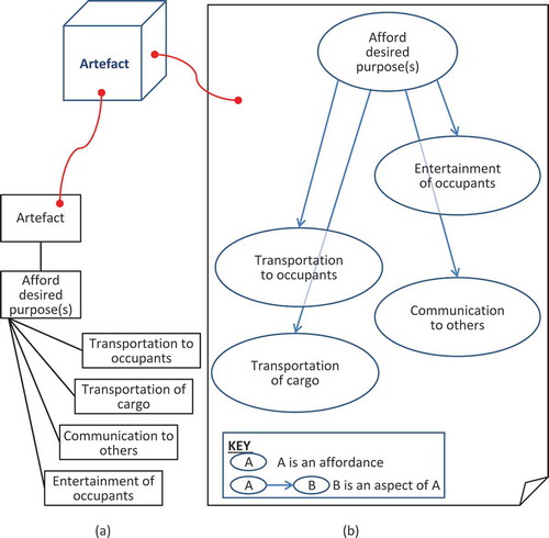
This example, illustrates how the principles for defining design structures in this paper might be applied to support affordance-based design. A more detailed example for a specific design activity would be needed to develop this example further. However, by combining this and the previous example, it is possible to imagine how affordance structures might be related to function and physical structures to support an affordance-based design process. In doing this, further opportunities to enrich affordance-based design activities by relating affordance, function and physical structures to users (who are explicitly captured in Cormier et al.’s model) and the processes that involve using the designed artefacts emerge. Halfmann, Elstner, and Krause (Citation2011) identify comparable relationships between product and process structures in the manufacturing domain.
Discussion
That a given design can be assigned multiple structures is self-evident from engineering practice. The principles introduced in this paper assert that a given structure includes elements of a kind and relationships of a kind. Using these principles as an analysis tool can clarify the nature of product data being used and generated in engineering processes. The principles are deliberately abstract and the nature of the kinds of element that might exist in a design structure is beyond the scope of this paper. Two kinds of relationship in design structures have been introduced. Composition relationships are the most well understood (Simons Citation2000) but even the simple examples introduced in this paper highlight complexities when applied to real-world engineering examples. Connection relationships are less well understood. More work is needed to create a theoretical basis for connection relationships. From the work completed to date, kinds of connection relationship depend on the type of element being connected, and this may also apply when relating relationships. As a foundation for this, there is a need for well-defined test cases because, although introducing interesting ideas, the examples provided in many sources are insufficient for readers to extract key information and use it in new contexts. In parallel, further work is needed to understand how best to define the purposes of design structures. These structures, as instruments for designers and other practitioners in the product lifecycle, are themselves designed, which begs questions around the application of engineering design methods to the design of design structures. If this were feasible then methods such as affordance-based design could be used in the development of structures to support a range of through-life engineering activities and processes.
The six principles for design structuring introduced in this paper have been used to inform the definition of a template for product structuring whose value has been demonstrated through application to four case studies. The first three case studies illustrate the value of the principles as a design definition and manufacturing analysis tool through application to sample products. In the fourth case study we show how the principles might facilitate generative aspects of engineering design processes in the role of a design development tool and their potential to relate product and process structures. The template assumes a representation of the design exists. Early in a design process, this is unlikely to be the case. However, in creating design structures, the representation of the artefact need not be complete. Completeness of a design depends on the design stage it is at. This highlights important issues for design practice. Creating design structures can highlight key sub-systems of the designed solution and the availability of design structures offers the potential to develop design visualisation tools to make explicit when design solutions become embedded into the design process. Design and innovation literature notes that a barrier to creativity and the quality of design outcomes can be design fixation (Linsey et al. Citation2010; Toh and Miller Citation2013) resulting from fixing the BOM structure too soon. The principles introduced in this paper could allow design fixation risks to be highlighted and support design managers in managing them.
In addition to being related to a representation of a physical artefact, design structures can be related to each other, ideally with separate relationships so that the structures remain independent of each other. For example, Cormier, Olewnik, and Lewis (Citation2013) give examples that, using the principles introduced in this paper, would be defined as separate design structures (compositions of affordances), related to each other through different user groups of the artefact under consideration. More broadly, relationships between design structures can be seen as akin to Suh’s (Citation1990) design matrices in that they are a means of relating (through mappings) design structures in different design domains (e.g., physical and functional). In other cases, multiple design structures can be extracted from a single visualisation. A common example can be found in general assembly drawings where a BOM for the assembly is defined, often as a parts list, along with key assembly-mating relationships. And finally, some design structures are related to the design via other structures. An example of this occurs in the fishing game example used earlier where the centre line referred to from the function structure does not exist in the shape representation.
An exciting area for development of the principles introduced in this paper lies in their potential to underpin generative design development tools. Shape and spatial grammars can be regarded as design structures where the arcs define transformation processes and can be used to understand the development of a design. In the longer term, a coherent collection of principles for design structuring offers the potential to apply shape grammar-like formalisms to non-shape elements such as functions. Supporting manufacturing and later through-life support processes creates an engineering need for designers to be able to consider the consequences of their decisions on downstream processes. Systematic ways of articulating design structures through-life offer the potential for through-life analysis tools that can be used during design to identify potential issues (or areas of risk) with respect to downstream processes. A theoretically sound formalism for design structures could enable the definition of design structures through life, offering opportunities for organisational learning and improved communication across product life-cycles.
Conclusions
Design structures may be regarded as lenses to view designs. For a physical product, designs have shape and material properties. Design structures are instruments to support engineering processes that are akin to conceptual models and root definitions in soft systems modelling. Design structures are not a property like shape or properties associated with materials – they are models of viewpoints on an object that help to understand it and to facilitate its design, rather than models of the object itself.
In this paper, we have demonstrated that the principles are straightforward to use, and provide the beginnings of a formalism that can be applied across a wide range of design structures. Without a well-founded and formally defined underlying theory, however, it is not possible to prove that the principles apply with full generality. The principles relate to the systematic specification of architectural aspects of design structures. Design structure definitions also need systematic ways of specifying their elements and the relationships between them. For composition structures, parallels with solid modelling can be drawn where the existence of a mathematical foundation for definitions (constructive solid geometry) offers potential for the development of automated tools for the validation and verification of instances.
A parallel mathematical theory for connection relationships has not yet been identified or developed. Drawing parallels with shape modelling, a general-purpose validation and verification method that can be applied during the definition of a structure may not be feasible. For example, if connection relationships are akin to the verification of a CAD model in manufacturing, then information and requirements for verification algorithms come from downstream applications that may not be available during the design process, and which require different kinds of expertise and competency than that of a typical design engineer. The examples provided in this paper show that connection relationships depend to some extent on the type of element being connected and, e.g., in shape, the composition structure of the elements concerned.
The principles introduced in this paper have been demonstrated through application to mechanical engineering design problems. The paper includes four case studies that explore the potential use of the template in different scenarios. Although ‘imaginary’ scenarios (exemplars), they do provide an insight into the potential application and usefulness of the approach in structuring and gathering design and manufacturing information. Other work has shown that the same principles can be applied to the engineering processes and networks of organisation that are needed to deliver designs to markets. Early results from ongoing work shows that change histories and similar meta-data generated through design processes can also be effectively represented as design structures. A key benefit of using a common framework for the description of many different kinds of design structure lies in the potential this offers for integrated design descriptions. Whilst care needs to be taken to ensure that creating such descriptions adds value, their availability promises major improvements in core areas. For example, emerging 3D printing technologies enable the 3D printing of mechatronic and robotic devices. A design description scheme that can support both mechanical and electronic aspects of such designs could offer significant benefits in the development of integrated solutions. More widely, there are obvious overlaps with other design disciplines but further work is needed in this area. For example, application in software engineering would need to ensure support for the definition of recursive design structures and the potential for this approach in bioinformatics could well be a key tool in the development of stratified medicines.
Our long-term goal is to establish an integrated theory that draws together grammatical and mereological theories of design. Applying such an approach to the synthesis of new designs could elevate the work of a designer above the detailed nuances of individual designers without diminishing their creativity and ingenuity.
The long-term impact of an integrated theory for engineering design would be coherent underlying principles for design definition and synthesis that could be used in design practice and education and as foundations for the development of future design, manufacturing and lifecycle support systems. This, in turn, could lead to step-change improvements in the performance of the innovation processes that depend on effective and efficient engineering design processes, so resulting in the faster delivery of improved products to market using fewer (e.g., financial and natural) resources.
Acknowledgements
This paper builds on research carried out on a number of projects including Immortal Information and Through-Life Knowledge Management (KIM) (ESRC/EPSRC reference EP/C534220/1); Design Synthesis and Shape Generation (AHRC/EPRSC) and Designing with Vision (The Leverhulme Trust). The data for the car jack case study were provided by Peter Hayward, an engineering design instructor at the University of Leeds. We thank anonymous referees whose feedback contributed to the paper’s development.
References
- Agouridas, V., A. McKay, H. Winand, and A. de Pennington. 2008. “Advanced Product Planning: A Comprehensive Process for Systemic Definition of New Product Requirements.” Requirements Engineering 13: 19–48. doi:10.1007/s00766-007-0055-z.
- Andreasen, M. 1999. “The Role of Artefact Theories in Design Science.” General Design Theory GDT’99 Workshop. Cambridge, MA: Engineering Design Centre, University of Cambridge.
- Andreasen, M. M., C. T. Hansen, N. H. Mortensen. 1997. “On the Identification of Product Structure Laws.” In 3rd WDK Workshop on Product Structuring, edited by M. M. A. Tichem and A. H. B. Duffy. Delft: Delft University of Technology.
- Anon. 2014. Research Project “The Dual Nature of Artefacts” [Online]. Delft University of Technology. Accessed January 21, 2014. http://www.dualnature.tudelft.nl/.
- Booth, J. W., T. Reid, and K. Ramani. 2013. “Understanding Abstraction in Design: A Comparison of Three Functional Analysis Methods for Product Dissection.” ASME 2013 International Design Engineering Technical Conferences and Computers and Information in Engineering Conference, IDETC/CIE 2013, Portland, OR, August 7.
- Borjesson, F., and U. Sellgren. 2013. “Fast Hybrid Genetic Clustering Algorithm for Design Structure Matrix.” ASME 2013 International Design Engineering Technical Conferences and Computers and Information in Engineering Conference, IDETC/CIE 2013, Portland, OR, August 7.
- Cagan, J., and C. M. Vogel. 2002. Creating Breakthrough Products: Innovation from Product Planning to Program Approval. Upper Saddle River, NJ: Prentice Hall.
- Chiriac, N., K. Hölttä-Otto, D. Lysy, and E. S. Suh. 2011. “Three Approaches to Complex System Decomposition.” 13th International Dependency and Structure Modelling Conference, DSM’11, Cambridge, MA, September 15.
- Cormier, P., A. Olewnik, and K. Lewis. 2013. “Towards a Formalization of Affordance Modeling in the Early Stages of Design.” ASME 2013 International Design Engineering Technical Conferences and Computers and Information in Engineering Conference, IDETC/CIE 2013, Portland, OR, August 7.
- Dement, C. W., C. E. Mairet, S. E. DeWitt, and R. W. Slusser. 2001. Mereos. Materials and Manufacturing Directorate, 45433–47750. Marietta, GA: Air Force Research Laboratory, Air Force Materiel Command, Wright-Patterson Air Force Base, OH.
- Dubois, A., and L.-E. Gadde. 2002. “Systematic Combining: An Abductive Approach to Case Research.” Journal of Business Research 55: 553–560. doi:10.1016/S0148-2963(00)00195-8.
- Dym, C., and P. Little. 2009. Engineering Design: A Project Based Introduction. Hoboken, NJ: Wiley.
- Fan, Z., M. M. Andreasen, J. Wang, E. D. Goodman, and L. Hein. 2005. “Towards an Evolvable Chromosome Model for Interactive Computer Design Support.” International Conference on Engineering Design, ICED 05, Melbourne, August 18.
- Halfmann, N., and D. Krause. 2012. “Assembly Time Estimation Model for Early Product Design Phases – Concept Development and Empirical Validation.” International Design Conference – Design 2012, Dubrovnik, May 24.
- Halfmann, N., S. Elstner, and D. Krause. 2011. “Product and Process Evaluation in the Context of Modularization for Assembly.” International Design Conference on Engineering Design, ICED11, Technical University of Denmark, Lyngby, August 18.
- Iacob, R., D. Popescu, and P. Mitrouchev. 2012. “Assembly/Disassembly Analysis and Modeling Techniques: A Review.” Strojniški vestnik – Journal of Mechanical Engineering 58: 653–664.
- ISO 10303-239. 2012. Industrial Automation Systems and Integration – Product Data Representation and Exchange – Part 239: Application Protocol: Product Life Cycle Support. Geneva: ISO.
- Lewis, K., D. Moore-Russo, P. Cormier, A. Olewnik, G. Kremer, C. Tucker, T. Simpson, and O. Ashour. 2013. “The Assessment of Product Archaeology as a Platform for Contextualizing Engineering Design.” ASME 2013 International Design Engineering Technical Conferences and Computers and Information in Engineering Conference, IDETC/CIE 2013, Portland, OR, August 7.
- Li, Z., and D. Tate. 2013. “Interpreting Design Structure in Patents Using an Ontology Library.” ASME 2013 International Design Engineering Technical Conferences and Computers and Information in Engineering Conference, IDETC/CIE 2013, DETC2013-13191, Portland, OR, August 7.
- Linsey, J. S., I. Tseng, K. L. Wood, C. Schunn, K. Fu, and J. Cagan. 2010. “A Study of Design Fixation, Its Mitigation and Perception in Engineering Design Faculty.” Journal of Mechanical Design 132: 12. doi:10.1115/1.4001110.
- Ma, J., and G. Kremer. 2013. “An Analysis of Decomposition Approach Applications in Design Engineering & Suggestions for Improvement.” International Conference on Engineering Design, ICED13. Seoul: Sungkyunkwan University.
- Maier, J., and G. Fadel. 2009. “Affordance Based Design: A Relational Theory for Design.” Research in Engineering Design 20: 13–27. doi:10.1007/s00163-008-0060-3.
- McKay, A., and A. de Pennington. 2001. “Towards an Integrated Description of Product, Process and Supply Chain.” International Journal of Technology Management 21: 203–220. doi:10.1504/IJTM.2001.002908.
- McKay, A. 1997. “A Framework for the Characterization of Product Structures.” In 3rd WDK Workshop on Product Structuring, edited by M. M. A. Tichem and A. H. B. Duffy. Delft: University of Technology.
- Mortensen, N. H., ed. 2003. Proceedings of the 6th WDK Workshop on Product Structuring - Application of Product Models, 23.-24.01.2003. Lyngby/Copenhagen: The Design Society.
- Pahl, G., and W. Beitz. 1999. Engineering Design: A Systematic Approach. London: Springer-Verlag.
- Samy, S. N., and H. ElMaraghy. 2010. “A Model for Measuring Products Assembly Complexity.” International Journal of Computer Integrated Manufacturing 23: 1015–1027. doi:10.1080/0951192X.2010.511652.
- Simons, P. 2000. Parts ‘A Study in Ontology’. Oxford: Clarendon.
- Steward, D. T. 1981. “The Design Structure System: A Method for Managing the Design of Complex Systems.” IEEE Transactions on Engineering Management 28: 71–74.
- Stiny, G. 1991. “The Algebras of Design.” Research in Engineering Design 2: 171–181. doi:10.1007/BF01578998.
- Stiny, G. 2006. Shape: Talking About Seeing and Doing. Cambridge, MA: The MIT Press.
- Suh, N. P. 1990. The Principles of Design. New York: Oxford University Press.
- Szabó, B. A. 1993. “The Problem of Reliability in Numerical Simulation.” In Control and Dynamic Systems V58: Computer-Aided Design/Engineering, Part 1, edited by C. T. Leonides. San Diego, CA: Academic Press.
- Tichem, M., T. Storm, M. M. Andreasen, and K. J. MacCallum, eds. 1995. Proceedings of the 1st WDK Workshop on Product Structuring, Delft University of Technology, Delft, June 22–23.
- Toh, C. A., and S. R. Miller. 2013. “Visual Inspection or Product Dissection? The Impact of Designer-Product Interactions on Engineering Design Creativity.” ASME 2013 International Design Engineering Technical Conferences and Computers and Information in Engineering Conference, IDETC/CIE 2013. Proceedings of the 10th International Conference on Design Education, Portland, OR, August 7.
- Trott, S. J., J. E. Baxter, A. McKay, B. Henson, and A. de Pennington. 1999. “Supporting Product Introduction Processes through Product Structures.” ASME Design Engineering Technical Conferences, Las Vegas, NV, September 12–16. ASME.
- Ulrich, K. T., and S. D. Eppinger. 2008. Product Design and Development. New York: McGraw-Hill.
- Wæhrens, B. V., Y. Cheng, and E. S. Madsen. 2012. “The Replication of Expansive Production Knowledge: The Role of Templates and Principles.” Baltic Journal of Management 7: 268–286. doi:10.1108/17465261211245454.
- Wu, C., B. Ciavola, and J. Gershenson. 2013. “A Comparison of Function- and Affordance-Based Design.” ASME 2013 International Design Engineering Technical Conferences and Computers and Information in Engineering Conference, IDETC/CIE 2013, DETC2013-12349, Portland, OR, August 7.