
 ?Mathematical formulae have been encoded as MathML and are displayed in this HTML version using MathJax in order to improve their display. Uncheck the box to turn MathJax off. This feature requires Javascript. Click on a formula to zoom.
ABSTRACT
The MRO (Maintenance, Repair and Overhaul) industry expected economic growth is severely limited by the high human injury and death toll rates, mainly associated to harsh working environment and scarcity of unmanned support solutions. The present work introduces an advanced mobile robotic platform that is capable of providing a clear response to key MRO barriers being designed to climb vertical surfaces and operating in harsh environment while executing inspection and repairing tasks. The paper outlines the integrated design procedure supporting the engineering of the mobile platform; the benefits of the solution have been addressed and validated with regard to real world operating scenarios.
1. Introduction
Inspection and repair, especially offshore, are still entirely human based activities where the employed workforce are extremely skilled in running manufacturing tasks and undertaking complex decisions in very critical operating scenarios (). Such context is aggravated by asking to men and women to deal with limited possibilities to be dextrous pushing their physical and cognitive boundaries, with consequent reduction of their perceptions of fit and misfit with their environment.
Figure 1. Examples of inspection and repair tasks in dangerous and confined conditions
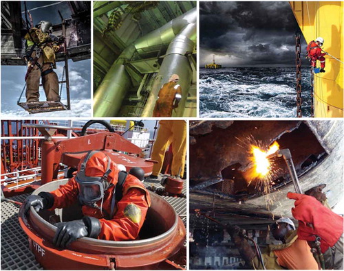
In order to reduce the risks associated to such activities, the MRO sector is subject to yearly new laws and workplace restrictions. Despite the introduction of always more stringent safety procedures and the adoption of innovative resources oriented to preserve the human health (Bakker and Demerouti Citation2007; Evans, Cohen Citation1987 Leather, Zarola, and Santos Citation2010), the world of MRO assists to the death of 3.5 thousand expert human operators and 3.3 million non-fatal injuries per year (As of January, 2021, the Eurostat listed on its website). Today, the robotic systems have been recognized as potential solutions to be combined with new working procedures and drastically reduce the risks for human operators. The design and development of the robotics solutions for MRO represents an ambitious challenge from a number of different perspectives, from technical to deliberative and social ones. Technically, the solution must be conceived to work in harsh environments while running inspection and repairing tasks demanding for integrating equipment and identifying/implementing always tailored process chains based on the very specific operating context. Deliberative challenges refer to the ability to be context aware while tuning and adapting the process mission on the basis of the human safety target, thus being able to determine the situation where it becomes necessary for robots to support or even substitute humans in running maintenance tasks. Social challenges primarily deal with the robot ability to become a building block of the maintenance team without altering synergies and collaborative skills or diminishing humans’ sense for safety, dexterity and autonomy.
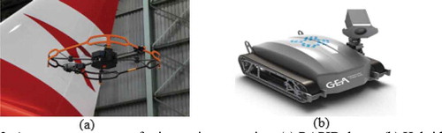
The current work focuses on the technical challenges pertaining the integration of robotic solutions into complex MRO setups. The most diffuse robotic systems consist of conventional-design robots or drones integrating specific pieces of equipment that are utilized to run well-known maintenance operations. Some solutions are quite specific applications. For instance, MRO drone (As of 1 January 2021, the Madrone listed on its website) conceived a drone solution ()) equipped with high definition imaging systems to acquire data from airplane fuselages detecting surface defects. Another example of available robotic system has been designed by Invert Robotics (As of 1 January 2021, the Invert robotics listed on its website), which developed an autonomous climbing robot to inspect the curved surfaces of stainless steel tanks used in the dairy, food and drink industry ()).
Figure 2. Autonomous systems for inspection operation: (a) RAPID drone, (b) Hybrid Crawler robot
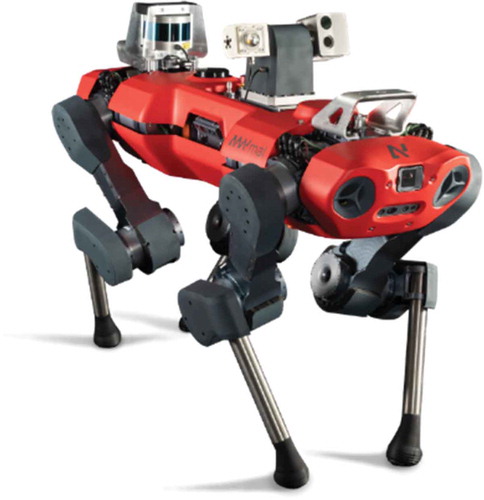
Some other robotic solutions are more versatile with regard to the operating context. For instance, ANYmal from ANYbotics (As of September, 2020, the ANYbotic listed on its website) represents the most articulated robotic solution employed to execute pre-defined missions by mounting a range of sensors to collect and interpret physical properties of equipment and environments.
1.1. Researches in mobile robots design and functionalities
Multiple mobile platforms have been designed over the last 10 years in order to operate in different sectors including industrial, research, inspection and high-risk operations. For instance, mobile robot systems have been designed to operate in the area of sewer cleaning (Birkenhofer et al. Citation2003) and thermal power plants (Gao et al. Citation2008, 610–615) The robots navigate in sewer tunnels and over big silos to perform inspection operations consisting to measure the state of important components and successively perform simple cleaning tasks. Further research activities regard the employment of autonomous robotic systems in more complex environments like in big industrial plants (CitationArbeiter et al.) and material flow systems (Bücker Citation2011; Brutscheck Citation2012). In such context, the maintenance robot can navigate autonomously within the plant () with the help of the plant model and sensor-based path detection. Other solutions include the design of different mobility approaches from 4-legs solutions (As of 20 December 2021, the DFKI, IA, IIT, Unitree, MIT listed on their website), 6-legs solutions (As of 20 December 2021, the HEBI and FZI listed on their website), wheeled solutions and tracked solutions (As of 1 January 2021, the OMRON, UBO, INUKTUN listed on their website) to improve the flexibility of the robots. Despite the latest efforts to design innovative mobile platforms, the developed systems are not capable to perform inspection and repair operations of complex tasks over vertical surfaces. This makes available solutions targeted on very specific applications, thus lacking the versatility that typically challenge automation in MRO and primarily leading to prefer human skills.
Figure 3. Autonomous inspection robot – ANYmal
Beside the design of new robotic architectures, high number of research activities have been carried out to enhance the current maintenance functionalities of the robots and their integration within the working environment. In particular, novel automated methods using Machine Vision Systems currently prove to reach or exceed the quality of human-driven inspection quality. The typical types of inspection tasks regard the identification of possible damages, their orientation, position, colour of specific features, as well as recognition of codes and geometric control (dimensions within tolerances) (Chauhan, Surgenor Citation2015). In addition, many machine-learning or deep learning-based methods have been proposed for solving specific tasks (Citak, Genc Citation2017; Viharos et al. Citation2016), while new trends in research focus on detecting extremely rare defects (Ecobar, Morales Citation2018, 1–16). Concerning the repairing operations, the literature is still missing research activities related to the development or improvement of the current maintenance skills of robotic solutions. In fact, recent researches like (Garcia et al. Citation2018) and (Ahmad, Babar Citation2016) associate the information, features and specifications of the identified damaged to the intervention of human operators.
Concerning the integration of the robots within the working environment, deep-learning (DL) has been widely used to solve artificial intelligence problems related to environment perception and related robot control. In the area of perception most of the works were focused on object detection (Eitel et al. Citation2015; Gupta et al. Citation2014; Ren et al. Citation2015) and environment recognition (Chen Citation2014; Goeddel, Olson Citation2016; Lin et al. Citation2015). Classical methods addressing the environment perception extract information from raw sensor data based on complex artificial features and are highly constrained by the adaptation to generic environments (Liu, Tang, Fang Citation2014; Moreno Citation2015; Rublee et al. Citation2011). However, robust algorithms modelling harsh weather conditions (Kutila et al. Citation2016) and unstructured environments are not yet available.
1.2. Robot’s limits in MRO sector
Despite the efforts of developing innovative and high-performance robotic systems to perform maintenance tasks in various industrial scenarios, the risks for the operator still exist and the future trend is as expected; the higher the number of new big plants, the bigger will be the risks for humans (As of 19 December 2020, the Bureau of Labor statistics listed on its website). Such condition is related to the development of robotic systems designed to address the inspection tasks but with limited capabilities and functionalities to operate in the rest of the maintenance chain. In fact, the current solutions are conceived as an operator-support system designed to facilitate and speed-up the inspection phase while the repairing processes still count on manual-based processes asking for the intervention of human operators. This approach results in a reduction of human exposure to hazardous situation during the inspection tasks but it does not guarantee the avoidance of injuries during the repairing phase.
Motivated by the need for designing robotic solution able to operate across the entire MRO chain, the current paper presents a novel solution of autonomous robot designed to be more adaptive, robust and reliable while performing maintenance tasks across both the inspection and repairing phases and ensuring a safer maintenance procedure. In particular, the design and development of the robotic platform have been carried out in reference to the maritime industry and the system performances have been evaluated through intermediate experimental tests.
2. Design method
The proposed robotic platform targets three main technological challenges: 1) design a robotic system able to operate in different MRO scenarios addressing enclosed space or difficult to access areas; 2) conceive a system able to integrate different inspection equipment necessary to acquire and collect data about the mechanical state of important components; 3) develop a robotic solution able to perform repairing tasks based on the acquired data and compliance with quality standards.
The design method employed to develop such robotic system consists of successive mechatronic design steps on the base of key features that characterize the MRO sector. illustrates a schematic representation of the design approach used to develop the robotic system highlighting the flow of the design activities.
Figure 4. Scenarios analysis, design, testing and validation
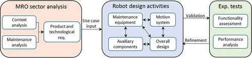
The proposed approach starts from the analysis of the industrial scenarios describing the reference operating context. This includes:
environment conditions that characterize each maintenance applications such as information about ambient temperature, weather conditions, presence of harsh elements (e.g. powders, chemical agents).
the maintenance operations detailing the materials, tasks to be performed, nature of the damages, data to be acquired by inspection tasks as well as repairing procedure and quality standards.
The context and maintenance tasks information are translated in process and product requirements, which represent the design constraints for the robot development as well as the requirements for the selection and integration of maintenance equipment.
The design of the robotic platform is conceived as an iterative process optimization between mechanical design, structural and fluid dynamic analyses. The next sections describe in detail the design and development activities carried out to realize the robotic solution. In particular, the document is structured in: context constraints and robot design requirement; engineering activities and robot design; experimental validation, conclusion and future works.
3. Context constraints and robot design requirements
The proposed system architecture is conceived to operate in maritime MRO value chain and running the following list of inspection and maintenance tasks:
corrosion detection and corrosion removal;
surface damages analysis and repairing process;
bulk and coating depositions respectively for mechanical reinforcement and surface protection.
Together with the maintenance information, the context analysis of maritime sector provided fundamental information for the design of platform’s mechanical architecture. In particular, the design of structure’s Degrees of Freedom (DoF), motion mechanism, adaptive elements and system functionalities are driven by the following context requirements:
operate in harsh environment;
execute the maintenance tasks over irregular surfaces with high roughness or presence of corrosion;
ensure the movement of the robot on horizontal and vertical surfaces.
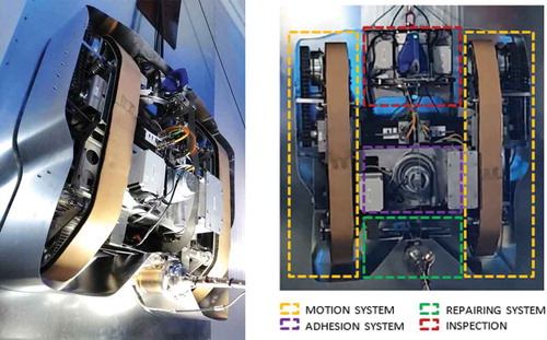
As a result of the aforementioned aspects, the proposed autonomous architecture consists of a robot composed by four main systems:
The motion system (Sec. 4.1.). It represents the mechatronic part of the robotic platform and it is designed to guarantee the movement of the robot in accordance with the context requirements 1 and 2.
The adhesion system (Sec. 4.2.). It is responsible to ensure the movement of the robot over vertical surfaces (context requirement 3) characterized by presence of corrosion, irregularities or asperities.
The inspection system (Sec. 4.3.). It interests the mechanical and sensing system design to address the detection, acquisition and elaboration of defect’s data (maintenance requirement 1 and 2).
The repairing system (Sec. 4.4.). It represents the actuator part of the robot and it is designed in order to address the repairing tasks for the maritime sector (maintenance requirement 2 and 3).
4. Engineering activities and robot design
4.1. The motion system
The proposed motion system consists of two tracks integrated on the left and right side of the robotic system. Each track is composed by a mechanical structure on which is integrated a belt used as interface between the robot and the external surface. The movement principle consists of synchronizing the rotation velocity of each track in order to follow a planned trajectory. In detail, by controlling the speed and direction rotation of each track, it is possible to address three different paths:
the linear movement is performed by imposing the same speed on both the tracks with same rotation direction;
the curved trajectory is address by reducing the velocity of one motor while keeping the other one constant;
the rotation of the robot along its central axis can be described by running the two motor with the same velocity and opposite direction.
The design of each track is carried out considering the worst operating condition of linear movement over a vertical wall. In detail, each track is designed taking into account all the forces – static loads, dynamic forces and friction forces – acting on the track. The total force applied on the track results the sum of each contribution as described by Eq. 1.
Where ,
,
and
are the total force, static loads, dynamic contribution related to the movement of the robot and the resulting force as sum of all friction forces.
In detail, the static contribution takes into account the weight of the preliminary version of motion system and an estimation of the weight related to the other three systems composing the robotic platform. The dynamic part of the equation concerns the force necessary to overcome the inertia of the system and accelerate the robot. The last contribution is computed as the sum of the friction forces generated by the components sliding on the external surface (e.g. tracks) and the internal friction among the components that constitute the track.
Starting from such value, it is possible to compute the minimum torque of the track actuator (electric motor) necessary to accelerate the robot until constant velocity over vertical surface. The minimum torque value is the total force acting on the track times the distance from the center of the motor. In order to reach high acceleration and torque values without integrating big size motor resulting in high robot weight, the motion system is based on multi transmission ratios. The first ratio (i = 2) is made of a steel chain responsible to transfer the torque from the driving gear connected with the motor to the driven gear directly connected with the track ()). The second transmission ration (i = 40) consists of a planetary gear head located between the motor and the driving gear ()). The total transmission reduction results in a ratio equal to 80, i.e. the product of the two contributions. Such ratio allows to integrate a motor with torque value 80 times smaller, thus reducing the weight and dimension of the overall motion system ()).
Figure 5. Schematic of motion system components
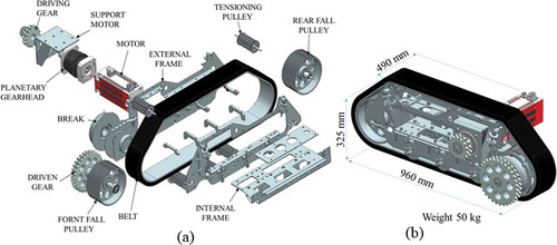
The actuation system is robustly connected to the system mechanical frame (). The material selected for the frame is an aluminium alloy, in particular the 5000 series with high concentration of Magnesium: as a result of the good welding properties, Al 5000 in fact represents an optimal solution to design high stiffness and lightweight mechanical frame. In addition, Al 5000 alloys have excellent resistance to corrosion, even in marine applications or harsh environments. The mechanical parts subject to high wear conditions (guide, rotational seat) are made of stainless steel 316 L material in order to increase the lifetime of the motion system. The combination of AISI 316 L with Al 5000 allows designing a mechanical system with a thermal homogeneous deformation; in particular, while executing long maintenance tasks, the robot structure is subject to thermal gradients that induce aluminium and stainless steel components to expand similarly (), thus generating little thermal stresses.
Figure 6. Schematic of robot track
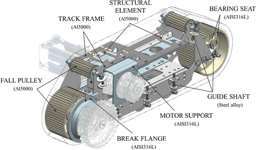
Table 1. Linear thermal expansion coefficient for metals
The robot movement is expected to occur over a variety of surfaces in terms of materials (Steel, composite materials, aluminium), superficial status (corroded, painted, high roughness) and surface geometries (presence of asperities or surface gap up to 10 mm). The operating requirements demand for high-performing tracks that could ensure a uniform contact force over the surfaces, even in presence of irregularities and asperities. Consequently, the track is custom-made and consists of two layers: the inner layer is represented by a toothed belt used to transfer the motion coming from the driven gear to the track (); the outer layer is made of EPDM rubber with high deformable properties and high friction coefficient. The two layers are glued together using industrial glue (SCOTCH-WELD 847) able to guarantee high adhesion strength, good shear resistance and optimal properties in presence of water or powders.
Figure 7. Schematic of custom-made belt
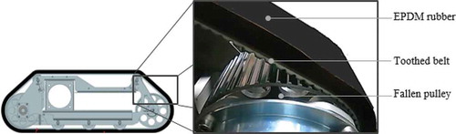
The dimension of the rubber area – in contact with the external surface – is equal to 100 mm (width) per 720 mm (length) presenting a maximum deformation of 25% of its thickness while subject to the force generated by the adhesion system (See The adhesion system section). Such deformation value allows the track to overcome surface asperity equal to 10 mm without affecting the traction of the motion system.
4.2. The adhesion system
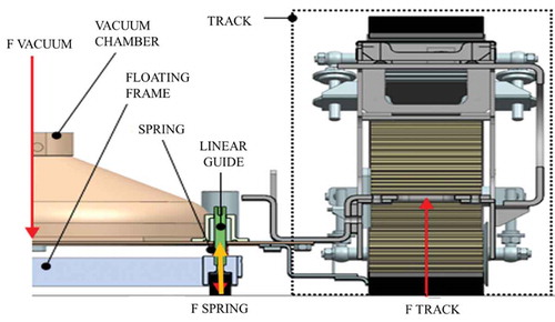
The adhesion subgroup relies upon an advanced concept of vacuum chamber whose size, material, vacuum level and robustness are driven by the context requirements. In detail, the adhesion system has the aim to generate an adhesion strength able to keep the autonomous robot attached to different working surfaces in terms of material, surface temperature (i.e. freeze, cold or hot), surface conditions (e.g. dry or wet) and surface roughness.
The proposed solution uses a continuous vacuum pump to generate a low-pressure atmosphere inside a sealed chamber and to guarantee the vacuum condition in case of undesired air infiltrations. The sealed chamber is conceived as a conical chamber made of stainless steel material which top side is closed by the vacuum pump and the bottom site is in contact with the external surface (). The sealing elements on the bottom part of the conical chamber ensure to avoid air leaks also when the robot is running on corroded, irregular or high roughness surfaces. In such case, the adhesion force generated by the system is proportional to the pressure difference between the inside part of the chamber and the external environment multiplied by the projected area of the chamber on the external surface (Eq. 2).
Figure 8. Schematic of vacuum chamber
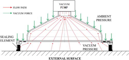
Where ,
,
and
are the adhesion force, ambient pressure, vacuum pressure and projected area of the chamber.
A preliminary design of the vacuum chamber is carried out by estimating the adhesion force necessary to keep the robot in contact with the surface considering the weight force of the robot in the worst operating scenario (repair of vertical surface). In such context, the minimum vacuum force () that must be ensured is equal to the weight of the robot (
) multiplied by the constant of gravity (
) and the friction coefficient (
) between the vacuum chamber and the surface (Eq. 3).
Eq.2 and Eq.3 allow computing the minimum value of pressure that the vacuum pump must target.
4.2.1 Sealing mechanism
The sealing mechanism is responsible to guarantee the vacuum pressure inside the vacuum chamber during the maintenance operations. In case of the presence of high air leaks, the pressure rapidly increases reducing the adhesion strength and consequent fall of the robot from the vertical surface. In order to avoid such issue, it has been designed an automatic sealing mechanism to ensure a homogeneous and constant contact force between the vacuum chamber and the external surface. The proposed solution consists of a passive floating frame on the bottom of which is integrated a rubber interface component. When running the motor-pump the vacuum pressure is generated and the entire robot structure is pushed toward the surface due to the force created by the pressure difference (). During such movement, the floating mechanism allows decoupling the reaction force of the tracks (
) from the force applied on the interface of the vacuum chamber (
). Such independent movement presents several advantages while climbing vertical surfaces:
ensure enough traction on the track to move the robot also during the presence of vacuum;
guarantee a contact force between the sealing frame and the external surface to avoid air leaks while running the robot over irregular surfaces;
make sure to overcome surface asperity or obstacles without reducing the adhesion force.
In detail, the floating movement is addressed by the integration of four linear guides on the sealing frame connected with the main robot structure, around which are placed torsional springs ().
Figure 9. Schematic of floating mechanism
The Eq. 4 describes the relation between forces involved in the floating mechanism.
Where the force generated by each spring is equal to the product of the spring stiffness () and the displacement of the vacuum chamber (
) when the vacuum pump is activated (Eq. 5).
As described from the equations above, any increment of the force applied on the floating frame causes a reduction of the force on the track compromising the track traction. On the other hand, reducing the force generated by the spring there is also a reduction of the sealing reliability with consequent increment of air leaks at the interface between the sealing elements and the external surface. For such reason, it is defined the right value of the spring stiffness in order to address the optimal threshold between track traction and sealing reliability. The proposed solution is based on multiple springs that can be interchanged in order to regulate the contact force in function of the surface conditions on which the system will operate (higher surface irregularity requires higher spring forces). To ensure the correct operation of the floating mechanism, the authors rely upon a Finite Element Method (FEM) analysis; this enables the evaluation of the effect of the forces on the structure deformations (). In case of high mechanical deformations, the linear movement could be locked preventing the correct functionality of the floating mechanism and consequently the efficiency of the vacuum system. In such context, a 3D FEM simulation campaign is performed: 3D tetrahedral elements are used as main finite elements to model the mechanical components while CBAR elements are used to simulate the screw connections. The welded junctions are scaled to glue element and the force generated by the spring and the vacuum pump is modelled as distributed load respectively applied at the corner of the vacuum chamber and the center of the body. At the bottom part of tracks are implemented fix constraints as boundary condition and the mass of the motor, pump and transmission elements are modelled as 1D elements with specific weight and inertia.
Figure 10. Finite element method model of the robotic platform: (a) robot architecture; (b) vacuum chamber
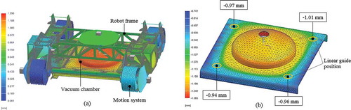
The numerical results show the vacuum chamber is subject to a quite symmetrical deformation behaviour. In detail, the maximum bend value is closed to 0.5 mm (1.283–0.772 mm) in the centre of the vacuum chamber and a displacement of 0.07 mm (1.01–0.94 mm) and 0.01 mm (0.97–0.96 mm) respectively over the diagonals of the chamber. The symmetrical deformation combined with low deformation values ensure the correct and free movement of the floating mechanism.
4.3. The inspection system
The definition of the inspection equipment that must be integrated in the robotic platform results from the analysis of the current repairing methods that characterized the MRO sectors. In detail, the inspection system focuses on the maritime sector as a consequence of the variety of damages typically available on site. In such context, common maintenance operations regard hull cracks, breaches or superficial corrosions. In case of cracks or deep superficial defects, for example, the damage is manually managed by measuring its dimensions, cutting out the surrounding patch and welding a new one, followed by quality inspection and certification (Jouko et al. Citation2010). With regard to the corroded areas, the repairing process consists of identifying the corroded area, remove the superficial oxide and applying a protective layer (e.g. painting). Among the available equipment to address the inspection tasks, the contactless inspection systems represent the optimal choice while considering flexibility, precision, reliability and recognizable defects. The proposed robotic solution integrates a 3D scanning system that represents the best trade-off between quality, cost and reliability in harsh applications (the selection of the 3D scanner is assumed as given for the sake of the paper clarity and will not be further elaborated) (As of 2020, the Artec3D listed on its website). The scanner allows inspecting a wide range of damages in terms of size and shape. Thanks to the acquisition of 2D and 3D images is respectively possible to provide information regarding superficial state (e.g. corroded area) as well as presence of big damages such as absence of material or cracks ().
Figure 11. Artec 3D scanning system [43]
![Figure 11. Artec 3D scanning system [43]](/cms/asset/b0291855-a461-4d84-9b1f-b1a9b76f0630/tcim_a_1925970_f0011_oc.jpg)
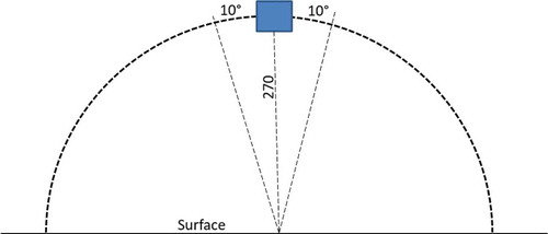
The 3D Scanner requires specific movement to acquire information with high resolution and precision. In particular, the scanner requires a tilting movement of ±10° around a virtual circumference with the centre in correspondence to the scan spot. Knowing the optimal focus range for 2D and 3D reconstruction of about 250–300 mm (distance between the scanner and the surface), the optimal tilting movement can be addressed by a movement along a circumference of radius 270 mm ().
Figure 12. Required tilting movement
In order to address high geometrical reconstruction quality, it is necessary to ensure a motion system with a high precision (±0.3°) and high repeatability (±0.2°). The employed mechanism is made of a circular guide with high precision guide carriage used as mechanical interface for the 3D scanner. The design starts by selecting the circular guide with curvature diameter nearest the required value (270 mm). Secondly, the carriage is designed considering the forces acting on the mechanism. In particular, the carriage is subject to radial/perpendicular loads and bending moments generated by the mass of the scanner. The loads and moments direction are analysed considering the operating set-up of the robot on vertical and horizontal surfaces. The carriage is selected among the available solutions in the market able to resist at the mechanical stresses generated by loads and moments. reports the developed tilting mechanism integrating the inspection scanner.
Figure 13. Mechanical architecture of tilting movement
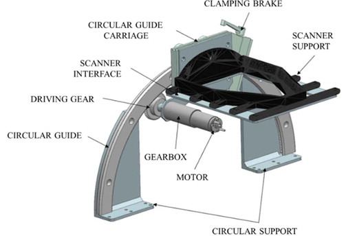
The movement of the carriage along the circular guide is enabled by a DC motor. The motor is designed to generate enough torque to contrast and accelerate the weight of the moved elements (scanner, carriage, scanner support and motor). In particular, the transmission mechanism is designed to ensure the motion performance required by the scanner (0.3 rad/s with ±0.3° precision). The position of the scanner is guaranteed by controlling the velocity and position of the DC motor measured through an increment encoder. The designed motion mechanism allows reaching a maximum scanner velocity equal to 0.18 rad/s with a precision of ±0.16°, which permits to move the scanner very precisely and perform surface acquisition with good precision (±0.05 mm) and resolution (±0.1 mm) over 180 × 150 mm area.
4.4. The repairing system
The integration of the repairing equipment to perform the maintenance tasks comes from the analysis of the current repairing methods that characterize the MRO sector. Cold Spray (CS) is a very promising technology when it gets to manage a wide range of damages in terms of dimensions and shape. In fact, thanks to its working principle (Papyrin Citation2006, 1–21; Lupoi et al. Citation2016, 545–548; Biermann et al. Citation2013, 559–562), CS allows performing both subtractive and additive processes:
running at low-pressure and low-temperature working conditions, CS operates similarly to sandblast process, thus being instrumental to remove superficial thin layers of oxide or painting;
running CS at higher working pressures and temperatures ensures the deposition of metal alloys and hence the repairing of extensive damages such as cracks.
The proposed CS solution (Valente, Gitardi, and Carpanzano Citation2020) is characterized by a novel low-pressure CS configuration (). Such CS module is designed targeting the best trade-off between compact dimensions and performance, which make such module a good solution to be integrated in the robotic platform for offshore applications.
Figure 14. ARM cold spray module
The proposed CS solution enables the deposition of high stiffness material (e.g. stainless steel) with lower spray conditions. In particular, the mean reaction force during the repairing process is closed to 40 N with peak values closed to 200 N. For this reason, the integration of the repairing module with the robotic platform demands for a high-stiffness mechanical structure and a robust vacuum system. The design and development of the mechanical interface for the CS module is carried out through an iterative process between mechanical construction and validation by FEM model. ) illustrates the mechanical structure enabling the assembly of the CS module to the robot. The process force is modelled as static load of 200 N applied at the mechanical flange of the CS module.
Figure 15. ARM cold spray module integration: (a) mechanical structure representation; (b) FEM model; (c) displacement in mm; (d) stresses in MPa
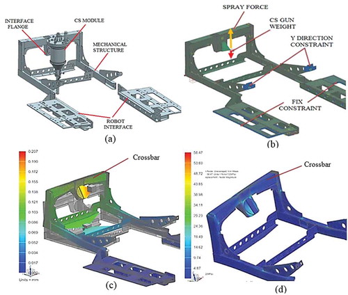
The designed mechanical structure presents low deformation – maximum value of 0.2 mm ()) at the interface of CS module – and admissible mechanical stresses of 54 MPa ()) as maximum value in correspondence of the higher crossbar (indicated in the figure). The structural results reveal the resulting deformation does not compromise the integrity of the mechanical interface while ensuring good accuracy of the repairing process.
5. Experimental test and validation
5.1. Motion system
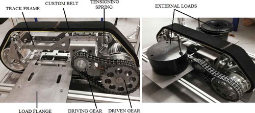
The designed motion system is validated through a set of experimental tests whose goal is to estimate its performance and its consumptions under the adhesion force. During the test, the system performances are evaluated across three indicators (KPI): 1) maximum torque generated by the track; 2) maximum traction force; 3) track electrical consumption. The experimental tests are carried out considering the working condition of movement over horizontal surface, with the adhesion system activated. In detail, the track is placed on steel surface and the frame is connected to an additional flange loaded with few mechanical loads to simulate the vacuum force (). The track is loaded with 125 kg equal to 0.5 times the theoretical force generated by the adhesion system. In such configuration, the prototype carries out a linear movement and the related motion data are acquired. The torque and electrical consumption are respectively monitored over time by the motor’s driver software. The traction force has been measured in a second experiment where the rear part of the track frame is connected with a digital dynamometer fixed to the wall and the traction force measured.
Figure 16. Motion system – experimental set-up
The experimental tests show that the designed motion system is able to effectively execute the movement under the external theoretical load generated by the adhesion system. The high torque of the motion system ensures the movement in presence of external forces. In particular, the proposed solution presents the following performance:
continuous torque 360 Nm;
maximum traction force 900 N;
electrical consumption 5 Amp
5.2. Adhesion system
The vacuum system represents the most critical component of the robotic platform since it is responsible to guarantee the adhesion and movement of the robot over the vertical surfaces. The validation of the vacuum system is performed through experimental tests. During the test, the adhesion performance of the designed system is evaluated across four KPIs: 1) Maximum vacuum pressure; 2) Maximum horizontal payload; 3) maximum detaching moment; 4) maximum surface asperity the system can manage. In detail, the vacuum system has been placed on vertical surfaces and a horizontal force has been applied in two different point of the vacuum chamber:
at the four corners of the chamber to simulate a horizontal force ());
Figure 17. Adhesion system – experimental set-up
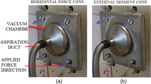
at the two top corners to simulate a detaching moment applied to the chamber ()).
For both experimental configurations it is recorded the maximum applicable loads, the vacuum pressure inside the chamber over flat surface as well as in presence of surface asperity ()
Figure 18. Adhesion system – surface asperity simulation
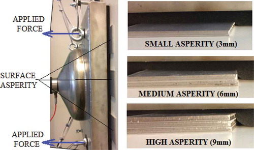
The experimental tests show that the designed adhesion system presents high adhesion forces to guarantee the movement of the robotic platform over vertical surfaces. The vacuum system is able to generate a high vacuum force to counteract external forces and moments applied to the robot. In detail, the proposed solution presents the following adhesion performance:
maximum vacuum pressure of about 65ʹ000 Pa;
maximum horizontal force applicable to the robot of 230 kg on dry surfaces and 170 kg on wet surfaces;
maximum detaching moment equal to 191 Nm;
adhesion forces guaranteed also in presence of high surface asperity of 9 mm.
6. Final solution of autonomous robotic platform
The final architecture of the proposed robotic platform consists of a main mechanical frame on which is integrated the motion, adhesion and maintenance systems. In detail, a motor pump – situated in the centre of the robot – is used to generate the vacuum pressure inside the adhesion system keeping the robot attached with the external surface. On the left and right sides of the vacuum chamber, the motion system is integrated and the correct movement is guaranteed by controlling the velocity of each track. Finally, the inspection module (3D scanner) and the repairing module (Cold Spray gun) are respectively integrated on the front and rear part of the robotic platform ().
Figure 19. Final solution robotic platform
The design of a high stiffness mechanical structure – with a maximum dimension of 1100x1050x385 mm and an overall weight of about 120 Kg – allows performing high precision and smooth repairing process while moving on vertical surfaces. A well-designed architecture allows operating in harsh environments characterized by operating temperatures ranging from −10 to 45 degrees with presence of powders and chemical agents as well as to move over wet and irregular surfaces. While moving the robot, the 3D scanner allows monitoring the state of the surface detecting corroded area, small and big size damages. The acquired data are used to analyse the nature of the damage and generate the optimal repairing strategy. Based on the inspection data, the robot performs the required repairing tasks relying upon the Cold Spray module. The high stiffness design of the robot frame with accessible mechanical and electrical interfaces along with 230 V, 24 V and air source up to 14.5 bar allow integrating different maintenance equipment you can scale up to address a variety of technology. lists the main feature of the developed robotic platform and its utilities.
Table 2. New autonomous robot performance and feature
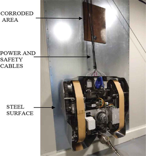
7. Robotic platform validation
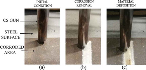
The validation of the robotic platform is carried out by simulating a maintenance task of the maritime application as the best industrial sector characterized by different surface conditions, defects shape, presence of corrosion and nature of damages. In detail, the proposed validation consists to climb a vertical steel surface on which is simulated a corroded area (). In such context, the robot must be able to move along the surface while analysing the superficial state of the surface and identify the surface damage. Once detected the corrosion, the robotic platform performed the inspection task with the 3D scanner acquiring information about the type, size and location of the damages. The acquired data are successively used to carry out the repairing tasks through the Cold Spray module. Such procedure represents a potential approach to reduce the maintenance time. The in-movement scanning allows to speed up the inspection tasks while the adoption of the Cold Spray module allows to face different type of repairing tasks (e.g. corrosion removal, material deposition, surface restoring) without interchange or integrate multiple tools resulting in faster repairing operations.
Figure 20. Robotic platform – maintenance simulation set-up
The designed robotic platform achieved the maintenance tasks by climbing the vertical surface thanks to the combination of its vacuum mechanism and motion system. During the climbing movement, the 3D scanner performed a continuous scanning of the surface detecting the corroded areas ()). Relying upon multi-image photogrammetry techniques, the images acquired by the 3D scanner are elaborated providing information about the nature of the damages, their size and locations ()). The acquired data are used to develop the tool path planning according with raster strategy to be executed during the repairing tasks ()). Finally, the robotic platform performed the repairing process in accordance with the planned trajectory addressing the surface restoration by two successive repairing tasks: 1) corrosion removal by running the Cold Spray process at low process conditions ()); 2) coating and surface repairing by depositing steel material ()).
Figure 21. Inspection task sequence and defect identification
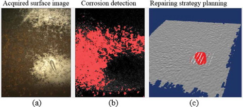
Figure 22. Inspection task sequence and defect identification
8. Conclusion and future work
This paper presents a new solution of robotic platform whose design targets the inspection and repair process for the MRO sector. The developed robot is characterized by maximum dimensions of 1200x1050x380 mm and an overall weight of about 120 kg. The platform mounts 3D inspection system and Cold Spray module respectively to detect and repair superficial damages. The inspection equipment is able to detect corroded areas and damages generating a 3D geometry with an accuracy of 0.05 mm. The inspection data are used to design the optimal repairing strategy and the respective robot path. The use of a vacuum system coupled with high-torque motion system permits to execute the maintenance operations on both horizontal and vertical surfaces also with presence of big asperity (up to 9 mm), corrosion or surface irregularities.
Future activities will focus on the optimization of the current mechanical structure in order to improve the weight-performance ratio as well as the validation of the solution in real maintenance scenarios. In addition, as a result of the experimental validations, further activities will focus on the optimization of the deposition strategy and associated path planning of the robot.
Acknowledgments
The research has been partially funded by project 4DHybrid: novel ALL-IN-ONE machines, robots and systems for affordable, worldwide and lifetime Distributed 3D hybrid manufacturing and repairing operations. Grant agreement no:723795.
Disclosure Statement
No potential conflict of interest was reported by the author(s).
References
- Ahmad, A., and M. A. Babar. 2016. “Software Architectures for Robotic Systems: A Systematic Mapping Study.” J. Of Syst. And Soft 122: 16–39. doi:10.1016/j.jss.2016.08.039.
- Arbeiter, G., A. Bubeck, J. Fischer, and B. Graf “Teleoperierte Mobile Roboter Warten Prozessanlagen.” Niedrigere Betriebskosten und höhere
- Bakker, A. B., and E. Demerouti. 2007. “The Job Demands‐Resources Model: State of the Art.” J. Of Managerial Psychology 22 (3): 309–328. doi:10.1108/02683940710733115.
- Bengel, M., K. Pfeiffer, B. Graf, A. Bubeck, and A. Verl (2019) “Mobile Robots for Offshore Inspection and Manipulation.” IEEE/RSJ International Conference on Intelligent Robots and Systems, St. Louis, p. 3317–3322
- Biermann, D., S. Goeke, W. Tillmann, and J. Nebel. 2013. “Improvement of Wearresistant Thermally Sprayed Coatings by Microfinishing.” CIRP Annals-Manufacturing Technology 62 (1): 559–562. doi:10.1016/j.cirp.2013.03.023.
- Birkenhofer, C., er al. 2003. “Ein Modulares Systemkonzept Eines Mehrsegmentigen, Autonomen Kanalroboters.” In Informatik Aktuell- Autonome Mobile Systeme 2003, 272–280. Berlin, Heidelberg: Springer-Verlag.
- Brutscheck, T. (2012) “Handhabungssystem Für Die Automatisierte Instandhaltung Von Stetigfördersystemen.” PhD thesis, Fakultät Maschinenbau, Technische Universität Dortmund, Shaker Verlag Aachen.
- Bücker, M. (2011) “Entwicklung Eines Mobilen Roboters Für Die Automatisierte Instandhaltung Von Materialflusssystemen.” PhD thesis, Fakultät Maschinenbau, Technische Universität Dortmund, Shaker Verlag Aachen.
- Chauhan, V., and B. Surgenor. 2015. “A Comparative Study of Machine Vision Based Methods for Fault Detection in an Automated Assembly Machine.” J of Proccedia Manufacturing 1: 416–428. doi:10.1016/j.promfg.2015.09.051.
- Chen, Z., O. Lam, A. Jacobson, and M. Milford. 2014. “Convolutional Neural Network-based Place Recognition.” arXiv 1411.1509.
- Citak, E., and Y. Genc (2017) “Machine Learning for Product Quality Inspection.” Signal Processing and Communications Applications Conf. Antalya, Turkey 15-18 May 2017.
- Eitel, A., J. T. Springenberg, L. Spinello, M. Riedmiller, and W. Burgard (2015) “Multimodal Deep Learning for Robust Rgbd Object Recognition.” IEEE Int. conf. Intelligent Robots and Systems, Hamburg, Germany, September 28 - October 02, 2015, 681–687. DOI: 10.1109/IROS.2015.7353446.
- Escobar, C., and R. Morales. 2018. “Machine Learning Techniques for Quality Control in High Conformance Manufacturing Environment.” J. Of Advances in Mechanical Engineering 10 (2): 1–16.
- Evans, G. W., and S. Cohen. 1987. “Environmental Stress.” In D. Stokols, & I. Altman (Eds.), Handbook of Environmental Psychology, 571–610.
- Gao, X., Z. Jiang, J. Gao, D. Xu, Y. Wang, and H. H. Pan (2008) “Boiler Maintenance Robot with Multi-operational Schema.” IEEE International Conference on Mechatronics and Automation, Takamatsu, Japan, p. 610–615.
- Garcıa, S., C. Menghi, P. Pelliccione, T. Berger, and R. Wohlrab (2018) “An Architecture for Decentralized, Collaborative, and Autonomous Robots.” IEEE Int. Conf. on Software Architecture, Seattle, WA, USA - April 30 2018 to May 4 2018, 75–7509.
- Goeddel, R., and E. Olson. 2016. “Learning Semantic Place Labels from Occupancy Grids Using Cnns.” J. Of Intelligent Robots and Systems 3999–4004. Daejeon, Korea.
- Gupta, S., R. Girshick, P. Arbelaez, and J. Malik (2014) “Learning Rich Features from Rgb-d Images for Object Detection and Segmentation”. Euro. Conf. on Computer Vision, Zurich, Switzerland, September 6-12., 345–360.
- Jouko, H., A. Toni, N. Jari, A. Jari, K. Dimitris, and E. Christos. 2010. Engineering Asset Lifecycle Management. J. London: Springer.
- Kutila, M., P. Pyykönen, W. Ritter, O. Sawade, and B. Schäufele (2016) “Automotive LIDAR Sensor Development Scenarios for Harsh Weather Conditions.” IEEE 19th Int. Conf. on Intelligent Transportation Systems, Convention Center, Rio de Janeiro, Brazil, 265–270.
- Leather, P., T. Zarola, and A. Santos. 2010. “The Physical Workspace: An OHP Perspective.” J. Of Occupational Health Psychology 225–249.
- Lin, T. Y., Y. Cui, S. Belongie, and J. Hays. 2015. “Learning Deep Representations for Ground-to-aerial Geolocalization.” In Computer Vision and Pattern Recognition, Boston, MA, USA, 5007–5015.
- Liu, R. Z., Y. Y. Tang, and B. Fang. 2014. “Topological Coding and Its Application in the Refinement of Sift.” IEEE Transactions on Cybernetics 44 (11): 2155–2166. doi:10.1109/TCYB.2014.2301797.
- Lupoi, R., C. Stenson, K. A. McDonnell, D. P. Dowling, and E. Ahearne. 2016. “Antifouling Coatings Made with Cold Spray onto Polymers: Process Characterization.” CIRP Annals-Manufacturing Technology 65 (1): 545–548. doi:10.1016/j.cirp.2016.04.015.
- Moreno, F. A., J. L. Blanco, and J. Gonzalez. 2015. “A Constant-time Slam Back-end in the Continuum between Global Mapping and Submapping: Application to Visual Stereo Slam.” Int. J. Of Robotics Research 35 (9): 1036–1056.
- Papyrin, A. N. 2006. “Cold Spray: State of the Art and Applications.” In Cold SprayTechnology, Elsevier Science, 1–21.
- Ren, S., K. He, R. Girshick, and J. Sun. 2015. “Faster R-cnn: Towards Real-time Object Detection with Region Proposal Networks.” J. Of Advances in Neural Information Processing Systems 91–99.
- Rublee, E., V. Rabaud, K. Konolige, and G. Bradski (2011) “Orb: An Efficient Alternative to Sift or Surf.” Int. Conf. on computer vision, Barcelona, Spain. 2564–2571
- Valente, A., D. Gitardi, and E. Carpanzano. 2020. “Highly Efficient Comoact Cold Spray System for In-situ Repairing of Stainless Steel Material Components.” CIRP Annals - Manufacturing Technology 69 (1): 181–184. doi:10.1016/j.cirp.2020.04.095.
- Viharos, Z., et. al. (2016) “Vision-based, Statistical Learning System for Fault Recognition in Industrial Assembly Environment.” IEEE Int. Conf. on Emerging technologies and Factory Automation, Berlin, DE.