
 ?Mathematical formulae have been encoded as MathML and are displayed in this HTML version using MathJax in order to improve their display. Uncheck the box to turn MathJax off. This feature requires Javascript. Click on a formula to zoom.
ABSTRACT
In recent years, there has increasingly been the requirement for turbine generators to operate more efficiently, and in a more flexible way. Traditionally, the effectiveness of assessment procedures used to predict component integrity has been established on the basis of service experience. As the demand has increased for new materials to be adopted after increasingly shorter development periods, and more efficient and flexible operation to complement the availability of renewable energies has become the norm, it has no longer been possible to evaluate assessment effectiveness on the basis of prior operating experience, since it did not exist. The solution has been to use the results of component-feature specimen tests. Initially, these were full section isothermal benchmark tests conducted at the maximum operating temperature. Now the verification of assessment effectiveness using component-feature specimen, service-cycle TMF testing has become more realistic and economically viable, with (i) component-feature specimens of a more conventional laboratory testing size, but meeting prior defined geometry and damage mechanism requirements, and (ii) service-cycle details based on the results of operation-based non-linear (elastic-plastic-creep) finite element analysis.
Background and introduction
Validating the effectiveness of assessment procedures using the results of component-feature specimen tests became increasingly more widespread during the 1970s. Previously, design procedures, in particular those for critical high-temperature turbine components, had typically been notoriously conservative and their effectiveness had relied on feedback from service experience. This was feasible because operating practices had become largely standard over a number of years, and there had been little driving force for the introduction of new materials. Thereafter, the dependence on service experience to verify new assessment procedure effectiveness became less realistic because of economic and environmental market forces driving:
the growing interest in life extension (at least in part, to exploit the prior adoption of over-conservative design philosophies),
the changes in operating duty, e.g. to higher application temperatures (to improve efficiency), and the reductions in turbine start-up times required from base-load to two-shift operation, and ultimately for renewable power source infill synchronisation, and
the consequent increase in research activity responsible for shorter metallurgical solution proof-of-concept and market-entry times.
In these circumstances, the solution was then to evaluate assessment effectiveness using the results of laboratory component-feature specimen tests.
Component-feature specimen testing
While there were early examples of high-temperature turbine-related feature specimen tests (e.g. [Citation1,Citation2], (), most component-type testing initially concerned assessing the integrity of full section thickness steam pipe and headers, and nuclear pressure vessel wall constructions (e.g. [Citation3,Citation4], (). As a generality, and because of the expense, most full-section component-feature specimen testing was conducted as part of collaborative projects (e.g. PERSC [Citation3], Euro-COST [Citation5], BE-CFAT [Citation6], BE-HIDA [Citation7] & BE-LICON [Citation8]). Most of the early high-temperature component-feature specimen tests were isothermal, conducted at the maximum application temperature [Citation2–4], although at least one type of turbine associated testing involved service-related thermal transients to tapered section disc specimens by means of alternate cyclic immersions in cold and hot fluidised beds (e.g. [Citation1]).
Figure 1. Examples of turbine component-feature specimen tests.
Figure 2. Examples of isothermal thick-wall section pressure vessel component-feature specimen benchmark tests.
Importantly, the early collaboratively funded component-feature specimen tests also provided the opportunity to evaluate the effectiveness of new sensing devices such as the Pecker short gauge length capacitance gauges (with a gauge length of ~2-3 mm), ideally suited to measuring strains in notch roots and across heat-affected zones at high temperatures [Citation9]. The Pecker development was novel because other welded high-temperature strain gauges, available at the time, had gauge lengths greater than ~10 mm (e.g. the CERL planar gauge [Citation10]).
Turbine operating cycles typically involve three phases, i.e. start-up, steady running and shut-down [Citation2], involving both primary (direct, mechanical) and secondary (self-equilibrating) loading. During the start-up phase, mechanical loading increases (e.g. due to increases in rotational forces and/or gas pressure), and the temperatures of critical locations increase more rapidly than the surroundings resulting in the transient generation of high thermally induced compressive strains (). Temperature gradients and consequent thermal strains generally become a minimum during steady operation, and the effects of mechanical loading predominate. During shut-down, the magnitude of mechanical loading approaches zero, while thermal loading at critical locations may peak in tension depending on cooling rate (before also approaching zero).
Figure 3. Schematic representation of influence of relatively slow (continuous grey lines) and relatively fast (solid black broken lines) heating/cooling rates on thermal strain generation at a critical turbine feature location.
In contrast to the schematic representation illustrated in , the thermal cycles experienced by real turbine components are invariably complex, and isothermal experimental simulations (and engineering assessments) have generally been based on idealised cycle types. One such example is shown in (which represents the shape of cycles following the first loading cycle). At turbine start-up, through wall thermal gradients can be responsible for the generation of large compressive strains in excess of the cyclic yield strain (OA, ). During steady running, temperature gradients are low and thermally induced strain levels are close to zero. Nevertheless, residual tensile stresses can be initially high due to reverse plasticity as a consequence of compressive yield during start-up (B). With total strain remaining relatively constant (in the absence of elastic follow-up effects), creep strain accumulation occurs as these stresses relax while the turbine is on load (BC). On shut-down, critical components may cool down slowly or rapidly depending on their location in the unit, with rapid cooling being responsible for a tensile peak strain (CD).
Figure 4. Schematic representation of simplified HP turbine service cycle adopted for isothermal benchmark testing.
Faster turbine start-ups are responsible for the generation of higher peak strains during the thermal transient (e.g. ) and higher magnitude peak stresses at the commencement of steady running (), invariably resulting in an increase in the fatigue damage accumulated per cycle and in the creep damage accumulated as a consequence of stress relaxation during on-load turbine operation. The effectiveness of traditionally adopted assessment procedures to account for more flexible operating requirements had not been examined, and this was an example of a design analysis requiring a fitness-for-purpose verification demonstration in a short time scale.
There was a significant improvement in high-temperature test machine control possibilities during the 1990s, when it became feasible to simultaneously vary and independently apply thermal and mechanical transients to conventional sized laboratory specimens in thermo-mechanical fatigue (TMF) tests [Citation11]. With this development, it became possible to devise component-feature-type experiments involving service type cycles and relatively small testpiece geometries, e.g. [Citation12–17]. Importantly, this provided a means of more rapidly verifying the effectiveness of state-of-the-art assessment procedures for evaluating the efficacy of new materials and new operating concepts.
For example, shows a turbine component-feature specimen, service-cycle TMF testing arrangement involving a circumferentially notched round tensile (CNRT) specimen, with a notch geometry determined to represent the features of a high-temperature rotor blade root fixing by non-linear finite element analysis (FEA) in accordance with the protocol outlined below [Citation13]. In this example, the notch root and gross section diameters of the CNRT specimen were 16 and 22 mm respectively. The thermal cycle experienced in the region containing the notch was the consequence of conduction from the specimen shoulders, which were heated by independently positioned induction coils, with this approach being adopted to minimise in-plane and out-of-plane thermal gradients associated with the presence of the notch. When necessary, a further control of such thermal gradients during TMF cycling could be achieved with an additional coil arrangement [Citation14]. In the example shown in , notch root strain was controlled by a diametral extensometer (with a linearity of ≤0.15% of the full scale measurement range), but with a back-up axial extensometer to monitor notch-opening displacement.
Figure 5. Example of turbine component-feature specimen, service-cycle TMF testing arrangement.
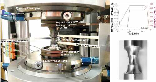
Examples of early service cycle shapes are shown in , where similarities with can be seen, and it is clear that cycle times are extended relative to those of conventional laboratory TMF tests to more closely relate to turbine service duty. For example, in the cycles shown, cycle times are 2 h and the hold time (representing the steady running period) is 1 h.
Figure 6. Representations of (a) hot-start, (b) warm-start, and (c) cold-start TMF service cycles for a blade root fixing in a high temperature 1%CrMoV turbine rotor (as adopted in [12]).
![Figure 6. Representations of (a) hot-start, (b) warm-start, and (c) cold-start TMF service cycles for a blade root fixing in a high temperature 1%CrMoV turbine rotor (as adopted in [12]).](/cms/asset/18c85159-650c-4a8c-84b5-db987be2348d/ymht_a_2173717_f0006_c.jpg)
It is important to recognise that the concept described in the following paper relies heavily on a knowledge of the geometry/dimensions and (design or actual) operational history of the component under evaluation. These details are required to define the cyclic stress/strain state at the critical location (as determined by non-linear FEA, see ii) below) and the shape of the critical feature. With this information, it is then possible to devise (also usually by non-linear FEA) a laboratory specimen geometry, incorporating the component representative critical feature exhibiting the stress/strain characteristics listed in ii) below for the service representative thermo-mechanical cycle detail. The employment of non-linear FEA is a key feature of the concept.
Von Mises equivalent strain is used to quantify the strain responsible for TMF damage in the groove roots of the component and specimen critical features. In each case, the relationships between εVM and εaxial, εdiam and εhoop are determined by FEA. In these circumstances, and for practical reasons associated with local dimensional scale, it is more realistic to control notch root strain in terms of εdiam (or diametral strain) than εaxial.
It has been shown that a number of turbine component critical features can be reasonably represented by the notch geometries in CNRT specimens, when the service-cycle TMF test design involved the following steps [Citation13]:
Non-linear (elastic-plastic-creep) thermo-mechanical analyses to identify the component creep-fatigue life limiting (feature) location and operating cycle, and
Determination of the cyclic stress-strain hysteresis behaviour at the life limiting surface location, and the associated stress/strain states at (and below) the surface in terms of: - mechanical strain range-
triaxiality factor, and - creep strain accumulated per cycle
and then, with this information:
(iii)Design of a laboratory cycle to replicate, as closely as practically possible, the turbine component feature in-service stress-strain hysteresis behaviour, and
(iv)Design of a laboratory specimen with a geometrical feature having the stress/strain characteristics at (and below) the groove root surface to be as close as possible to those identified in ii).
An important feature of the proposed component-feature specimen, service-cycle TMF tests is that they are conducted at least in accordance with existing standard practices for TMF testing [Citation18,Citation19].
Structural integrity assessment
Evaluation of the structural integrity of high-temperature turbine components may involve ‘defect-free’ or ‘defect’ (containing) assessment procedures (e.g. [Citation20]). While some sub-critical crack propagation may be tolerable from defects associated with features in certain high-temperature turbine components, their presence in others is not. Service-cycle TMF testing may be used to evaluate the effectiveness of ‘defect-free’ or ‘defect’ assessment procedures [Citation12–17].
It has been shown previously that a number of ‘defect-free’ assessment procedures (e.g. [Citation20–23]) may be represented schematically by the flow diagram shown in . This acknowledges that an important step in all high-temperature assessment procedures is determination of the state of stress and strain at critical locations in the component; with the requirements for: a knowledge of the external forces and thermal transients experienced during service duty; and representation of the cyclic and/or creep deformation properties of the material(s) of construction. Having established the stress/strain state history at critical locations, cyclic and creep damage fractions (DF and DC) are determined by reference to the appropriate material endurance property data, where DC may be determined as a function of creep-rupture strength or creep-rupture ductility (depending on the adopted assessment procedure and/or the type of loading). The DF and DC fractions are finally compared with, for example, the crack initiation locus in a creep-fatigue damage summation diagram, and the risk of cracking is thereby evaluated. Using this approach, it is important to acknowledge that the creep-fatigue crack initiation locus is dependent on material, temperature and the procedures used to determine DF and DC, and is now typically based on the results of appropriate laboratory tests (as well as prior service experience, if the information is available). Ideally, the creep-fatigue locus represents linear damage summation, but is more typically bi-linear (e.g. [Citation21,Citation23]) or potentially an even more complex function (e.g. [Citation24]).
Figure 7. Common steps in a number of published creep-fatigue assessment procedures (e.g. [20–23].
![Figure 7. Common steps in a number of published creep-fatigue assessment procedures (e.g. [20–23].](/cms/asset/0ec92003-42c3-4465-b7f1-afeea92fa7f7/ymht_a_2173717_f0007_b.gif)
Service-cycle TMF testing
An early example of the use of turbine service cycle type TMF testing was for a 1%CrMoV rotor steel [Citation12]. In this study, service cycles simulating hot-, warm- and cold-starts were adopted, as shown in . In these tests, the superimposed mechanical strain cycle representing the effects of rotational loading during operation was always the same, while the thermal cycle varied according to the adopted turbine start type. For the three cycle types, Tmax was always 565°C. However, for the hot-start cycle, Tmin was 350°C (to represent that following a short period of inactivity, such as an over-night stoppage); for the warm-start cycle, Tmin was 150°C (to represent that following an intermediate period of inactivity, such as an over-weekend stoppage); and for the cold-start cycle, Tmin was 50°C (to represent that following a longer period of operational inactivity, such as an inspection/maintenance outage).
The outcome from these tests was important for a number of reasons. Not only did it determine the form of the creep-fatigue crack initiation locus (for this material, maximum application temperature and adopted assessment procedure), but post-test examination revealed the mechanism of crack development. The outcome of the service-cycle TMF tests could not be regarded as practically meaningful if the damage mechanism generated was inconsistent with that likely to be associated with the service conditions of the component under evaluation.
In this respect, the post-test examination results of the 1%CrMoV rotor steel TMF service cycle tests shown in were informative. In , for the hot-start simulation, there was evidence of multiple transgranular fatigue crack initiation at the specimen surface and intergranular creep damage development from the specimen axis, towards the external surface. As a consequence of the hot-start TMF conditions, transgranular fatigue cracking into the specimen interacted almost immediately with creep damage emanating from the axis to propagate by an intergranular creep-fatigue mechanism. In contrast, for the cold-start cycle TMF test (), the dominant damage mechanism was the development of creep cracking from the specimen axis, with any evidence of surface fatigue crack initiation being consumed by strain enhanced oxidation. While the observations for the warm-start specimen appeared to indicate an intermediate condition (), the evidence suggested that the consequent crack development mechanism was mainly creep dominated. For the 1%CrMoV steel service-cycle TMF tests, only the hot-start test was responsible for creep-fatigue crack development from the external surface, while the warm- and the cold-start test in particular were responsible for creep crack development from the specimen axes ().
Figure 8. Damage development in 1%CrMoV TMF specimens subjected to (a) a hot-start TMF cycle, (b) a warm-start TMF cycle, and (c) a cold-start TMF cycle (see ).
While early service-cycle type TMF examples relied on the contribution of idealised mechanical strain cycles (e.g. [Citation12]), typical of those formerly adopted for isothermal representations (e.g. [Citation2–8]), more recent studies were based on the results of non-linear (elastic-plastic-creep) finite element analyses (FEAs) of actual turbine components in service (e.g. [Citation13,Citation15]). To illustrate the effectiveness of this latest development, a comparison is shown in of an enhanced non-linear FEA predicted rotor blade-fixing root stress/strain hysteresis (numerical) response with that which could be applied (experimental) in the groove root of a feature specimen, service-cycle TMF test [Citation13], e.g. .
Figure 9. Comparison of enhanced FEA rotor blade-fixing root (numerical) stress/strain hysteresis response with that applied (experimental) in a feature specimen, service-cycle TMF test [13].
![Figure 9. Comparison of enhanced FEA rotor blade-fixing root (numerical) stress/strain hysteresis response with that applied (experimental) in a feature specimen, service-cycle TMF test [13].](/cms/asset/4f247e33-5774-4d6d-9b0e-845527819c30/ymht_a_2173717_f0009_c.jpg)
Guidance for the design of representative component-feature TMF specimens (e.g. CNRT specimens) have already been described, along with the means of controlling thermal transient distributions in induction heated specimens with non-uniform sections (e.g. [Citation14]). Indeed, such is the level of digital test machine control that it is now feasible to apply even more complex TMF cycles with superimposed high vibratory stress loading (e.g. [Citation16]).
Concluding remarks
In recent years, as power generation turbines have increasingly been expected to operate in more flexible ways, there have been significant material performance improvements, and notable developments to the analytical procedures available for assessment of the structural integrity of critical high-temperature components. In the past, verification of the effectiveness of new assessment procedures to incorporate material performance improvements and/or state-of-the-art developments in structural integrity calculations could be based on prior service experience, but, more recently, the time required for this practice has become increasingly impractical.
Initially, the solution was to verify proof-of-concept in the required shorter market entry times using the results of isothermal close-to-full-size component-feature specimen tests at the maximum application temperature. Unfortunately, the cost and resource-availability of this type of high-temperature testing could be prohibitive. More recently, with the latest improvements in actuator and sensor technologies, and the digital control capabilities of modern test machines, the verification of assessment effectiveness using component-feature specimen, service-cycle TMF testing has become more realistic and economically viable, with (i) component-feature specimens of a more conventional laboratory testing size, but meeting prior defined geometry and damage mechanism requirements, and (ii) service-cycle details based on the results of operation-based non-linear (elastic-plastic-creep) finite element analysis.
Nomenclature
BE Brite Euram (European research funding agency)
CFAT Acronym for ‘Optimisation of Creep-Fatigue Assessment Procedures’ (European collaborative) project
CNRT Circumferentially notched round tensile (specimen)
COST European Cooperation in Science and Technology
DC, DFTotal creep damage fraction (accumulated in test), Total fatigue damage fraction (accumulated in test)
FEA Finite element analysis
HIDA Acronym for ‘High Temperature Defect Assessment’ (European collaborative) project
HP High pressure (turbine module)
LICON Acronym for ‘Methodology for Life Prediction and Condition Assessment of Steam Power Plants’ (European collaborative) project
PERSC Power Engineering Research Steering Committee
t time
Tmax, Tmin Maximum temperature, minimum temperature
TMF Thermo-mechanical fatigue
, εaxialVon Mises equivalent strain, Axial strain
εdiam, εhoopDiametral strain, Hoop strain
,
Von Mises equivalent stress, maximum principal stress
Disclosure statement
No potential conflict of interest was reported by the author(s).
References
- Woodford DA, Mowbray DF. Effect of material characteristics and test variables on thermal fatigue of cast superalloys. A review. Mater Sci Eng. 1974;16(5):5–43.
- Holdsworth SR. Factors influencing high temperature HSF crack growth rates in turbine casting steels. In: RA A, RP S, editors. Proc. Conf. on Behaviour of Defects at High Temperatures ESIS 15, Sheffield. March; 1992. p. 327–349.
- Coleman MC, Fidler R, Williams JA. Full size component testing under creep conditions. In: Gooch DJ, editor. Proc. Conf. on Techniques for Multiaxial Creep Testing, Leatherhead. 1986. 333–356. How IM, Elsevier Appl. Sci
- Kussmaul K, Maile K. Large scale high temperature testing of specimens and components - an essential tool for structural integrity engineering. Mater High Temp. 1998;15(2):119–124.
- Bressers J, Hurst R. Prediction of residual lifetime under simulated service loads. In: 3rd Annual Progress Report, COST501/2, WP5C, EUCO/MC5/01/92. 1992.
- Holdsworth SR, Maile K, Brown TB, et al., 1993, ‘Optimisation of methodologies to predict crack initiation and early growth in components under complex creep-fatigue loading’, Proc. Conf. on Life Assessment of Industrial Components and Structures, Churchill College, Cambridge, September
- Shibli IA. Overview of the HIDA project. Mater High Temp. 1998;15(2):1–6.
- Auerkari P, Holdsworth SR, Rantala JH, et al. Modelling the development of creep damage. In: Proc. baltica Conf. on Condition And Life Management for Power Plants. Helsinki: June; 2001.
- Holdsworth SR, Holt A, Scholz A. Experience with pecker capacitance gauges for the measurement of local strains at high temperatures. In: Proc. HTMTC/BAM Conf. Local Strain and Temperature Measurements in Non-Uniform Fields at Elevated Temperatures. 1996.
- Noltingk BE, Dfa M, Owen CKV, et al. ‘High stability capacitance strain gauge for use at extreme temperature’, Proc. Inst. Electrical Engineers. 1972;119:7.
- Hähner P, Affeldt E, Beck T, et al. Validated code-of-practice for strain-controlled thermo-mechanical fatigue testing. In: European Commission, JRC, EUR 22281 EN. 2006.
- Holdsworth SR, Mazza E, Binda L, et al. Development of thermal fatigue damage in 1CrMoV rotor steel. Nucl. Engng. & Des. 2007 December;237(24): 2292–2301.
- Holdsworth SR, Radosavljevic M, Grossmann P, et al. 2012. Effectiveness verification of creep-fatigue assessment procedures for fast-starting steam turbines. Proc. ASME Turbo Expo. 11–15. June. Copenhagen: GT2012–68223.
- Radosavljjevic M, Holdsworth SR. Novel induction heating system for service cycle TMF testing. Mater High Temp. 2009;26(4):369–374.
- Vacchieri E, Holdsworth SR, Poggio E, et al., Service-like TMF tests for the validation and assessment of a creep-fatigue life procedure developed for GT blades and vanes. 2017;I J Fatigue. 99:216–224.
- Hosseini E, Holdsworth SR. Cracking due to combined HCF and TMF loading in cast iron. 2017;I J Fatigue. 99:279–285.
- Azeez A, Norman V, Eriksson R, et al. Out-of-phase thermomechanical fatigue crack propagation in steam turbine steel – modelling of crack closure. I J Fatigue. 2021: 149
- ISO.12111. ‘Metallic materials – fatigue testing – strain controlled thermo-mechanical fatigue testing method. In: International Standards Organisation. 2011.
- ASTM E2368. Standard practice for Strain controlled thermomechanical fatigue testing. In: ASTM International. 2010.
- R5. An assessment procedures for the high temperature response of structures. In: British Energy Generation Ltd;. Barnwood.
- ASME, ‘Rules for the construction of nuclear facility components, Class 1 components in elevated temperature service, Boiler and pressure code, Section III, Division 1 – subsection NH’, American Society of Mechanical Engineers (ASME), New York.
- TRD 301. Annex I – design calculations for cyclic loading due to pulsating internal pressure and temperature. Technische Regeln für Dampfkessel.
- RCC-MR, ‘Design and construction rules for mechanical components of FBR nuclear islands, Section. 1 – nuclear islands components’, AFCEN:.
- Skelton RP, Gandy D. Creep-fatigue damage accumulation and interaction diagram based on metallographic interpretation of mechanisms. Mater High Temp. 2008;25(1):27–54.