
ABSTRACT
Single crystal material, of CMSX-4® alloy composition, was cast and secondary orientation was controlled at the machining stage, to produce c-ring cross-section tubes with known crystallographic orientations. The c-ring tubes were coated with NaCl before being subject to loading up to 700MPa and heated for durations of up to 2 hrs at 550°C in flowing environments containing air and SO2.
No cracking was observed in short term tests that were run in the absence of either NaCl, or SO2, indicating a symbiotic interaction is required to initiate cracking. Experiments confirm the presence of oxygen, chlorine and sulphur at the crack tips, formed along {001} crystallographic planes, however, they were distributed discretely, with several oxide and sulphide phases observed.
In this work, we image, analyse and identify the phases formed during the cracking and corrosion of CMSX-4® superalloy and hypothesise on the complex chemical interactions that take place during crack initiation.
Introduction
Turbine blade materials and design have evolved to enable modern day jet engines to operate with excellent efficiency and reliability. These alloys offer optimised high temperature strength, fatigue resistance and corrosion resistance in harsh environments. Turbine components must operate over a wide temperature range, whilst subject to high stresses and exposure to varied chemical environments. In this study, we use analytical electron microscopy to investigate environmentally assisted cracking of single crystal Ni-based superalloy test pieces. Under the most demanding conditions, in the hottest part of the engine, the operating environment involves temperatures greater than the alloy melt temperature and considerable mechanical loads; the combination of which make creep a significant issue. To cope under such extreme conditions, to which components are exposed, there has been a continuous development of turbine blade alloys, culminating in the implementation of single crystal Ni-based superalloy blades in the 1970s/80s [Citation1]. Since then, alloys have been optimised, providing greater resistance to creep deformation, a reduced susceptibility to oxidation and hot corrosion, and better fatigue performance, all of which have increased operation reliability and efficiency. Nowadays, single crystal blades are standard in all large engines for military and commercial aircraft.
In recent years, concerns have been raised over the propensity for environmentally assisted cracking of single crystal turbine blades, resulting in considerable financial costs to the industry. Potential issues related to environmental conditions, including an increased level of pollutants in the air, are believed to have increased the rate of sulphidation and cracking of the intermediate pressure (IP) blades, necessitating more regular service schedules. Type II low temperature hot corrosion attack of CMSX-4® alloy has been observed within the temperature range 600–800°C [Citation2–4], although Ni-based superalloys are susceptible to hot corrosion at temperatures as low as 450°C to 550°C [Citation5]. Type II attack involves reactions between sulphur containing gases and chloride bearing salts, producing sodium sulphates, which in turn deposit on un-coated regions of hot-section components in the engine. Further reactions with the Ni-based superalloy surface can result in the formation of low melting point eutectics, which leads to an accelerated oxidation, or sulphidation attack of the alloy.
CMSX-4® is a second generation, high strength, rhenium containing, single crystal Ni-based superalloy developed by the Cannon Muskegon Corporation. Typically, this alloy is protected by the formation of slow growing, adherent, alumina and chromia oxide scales. In general, broad-front type II corrosion at 700°C results in the formation of an outward growing NiO and CoO layer and internal sulphidation of chromium and aluminium, at the original metal surface [Citation4]. In the presence of stress, and sulphur containing environments, at 550°C, cracks have been observed in CMSX-4® alloy after test durations of typically 100 hours, or greater [Citation6,Citation7]. Clear evidence showing that both sulphur and oxygen are present in cracks formed in Na2SO4/K2SO4 pre-coated, stressed (nominal 700MPa), CMSX-4® c-ring test pieces exposed to flowing SO2 in air is presented by Chapman et al. [Citation5]. Cracks were observed, propagating in a <001> direction, through γʹ precipitates, after 100 hours testing at temperatures of 450°C, 500°C and 550°C. However, previous work has indicated the presence of chlorine at the tip of cracks formed in CMSX-4® static load tests [Citation8], hence there is a suggestion that chlorine might play an important role in the cracking mechanism.
Materials and methods
C-ring test pieces were machined from single crystal cast bars of an alloy with a composition matching Cannon Muskegon’s CMSX-4® Ni-based superalloy (). Test pieces were produced with a <001> crystallographic orientation aligned approximately parallel to the cylinder long axis (). A load was applied by means of adjusting a bolt which passed through a pair of holes, drilled through the centre of the c-ring, perpendicular to its long axis. A full description, detailing the stress calculations of similar c-ring test pieces, is presented by Brooking, et al. [Citation7]. Test pieces were subject to a maximum constant stress of approximately 700MPa and pre-coated with a NaCl/water solution before being exposed to a flowing 50ppm SO2 in air environment at a temperature of 550°C.
Figure 1. Schematic representation of a c-ring test piece with orientation reference (image adapted from Brooking et al. [Citation7]).
![Figure 1. Schematic representation of a c-ring test piece with orientation reference (image adapted from Brooking et al. [Citation7]).](/cms/asset/98b83d98-821a-4b18-a571-cff68b2f6471/ymht_a_2182587_f0001_c.jpg)
Table 1. Alloy composition in wt % (nominal) [Citation9].
Scanning electron microscope (SEM) images were recorded using JEOL 7001F, Zeiss Gemini 450 and FEI Helios NanoLab 600i instruments. Samples were mounted in conductive resin and polished using standard metallographic techniques. Oil-based polishing lubricants were used to ensure the preservation of water-soluble salts.
Site-specific TEM lamellae samples were produced, using a FEI Helios NanoLab 600i dual beam focused ion beam (FIB) instrument, by the FIB lift-out method [Citation10]. Lamellae were thinned to electron transparency, using a 30kV Ga ion beam, before application of a final cleaning stage, using a 5kV beam energy.
Specimens were analysed using a JEOL 2100FCs probe aberration corrected scanning transmission electron microscope (STEM) and a LaB6 equipped JEOL 2100+ instrument; both operating at 200 kV.
Energy dispersive x-ray spectroscopy (EDS) was performed using a JEOL system on the 2100FCs aberration corrected STEM instrument and an Oxford Instruments system on the 2100+ microscope.
Results
Scanning electron micrographs of c-ring specimens exposed cracks running parallel to the c-ring long axis ()). After only 10 minutes, occasional cracks were observed, some approaching 200 µm in length. Following tests of 2 hours, cracks were more numerous and their lengths much greater (>0.5 mm) than were observed in the 10-minute exposure sample. EDS chemical analysis of c-ring surfaces revealed a nickel rich oxide layer interspersed with circular corrosion product features (previously salt rings) and relatively dark (low-z) areas of porous oxide surrounding the salt rings. EDS and high-resolution SEM images demonstrated that the lower-z regions surrounding the circular features were dual phase, made up of porous nickel oxide, the pores containing a beam sensitive material ()) enriched in Na, S and O, probably Na2SO4. When analysed from the surface, the oxide scale formed over sub-scale cracks, was most often enriched in aluminium, although on occasion, titanium and tantalum-rich scales were formed above cracks.
Figure 2. (a) SEM image showing parallel cracks (bright lines) emanating from salt-ring features on the surface of a CMSX-4 c-ring test piece, (b) low-z beam sensitive amorphous material in porous nickel oxide and (c) cracks in substrate beneath a cross sectioned salt ring, with EDS line-scan inset showing enhanced O, Cl and Al concentrations in a crack (2 hours testing at 550°C).
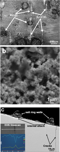
Cracks were observed on the surface of both the 10 minute and 2-hour exposure test pieces located near the c-ring apex. When viewed in cross section ()), straight cracks could be seen following, approximately, the [001] direction. Crack initiation occurred in locations where salt spray droplets had previously dried and in the surrounding regions of two-phase voluminous surface corrosion products. The inset EDS line-scan presented in ), demonstrates the enhanced oxygen, chlorine and aluminium concentrations measured in a crack formed in the 2-hour test specimen. Crack chemistry showed some variations; oxygen was always detected, often in conjunction with chlorine and/or sulphur.
C-rings presented in cross-section and analysed by SEM/EDS revealed an oxide layer, c.a. 1 µm thick, covering the exposed outer surface, after 15-minute test time. Following 2 hours exposure, a multi-layer oxide layer, totalling only 2, or 3 µm thickness was measured. Prior salt-ring walls, which coincided with the plane of the cross-section were >10 µm tall and in many cases, preferential internal corrosion was observed directly beneath the salt ring walls ()). Large field of view EDS maps revealed a continuous nickel oxide layer formed over the c-ring surface. In the vicinity of salt rings, a layer of chlorine-rich material was concentrated at the alloy/oxide interface; these regions were also enriched in aluminium.
Cross-sectioned c-ring specimens revealed cracks to depths approaching 70 µm after only 10 minutes and up to 200 µm after 2 hours testing. Primary cracks, which emanated from the c-ring surface and propagated into the CMSX-4 alloy, followed approximately a < 001> crystallographic direction. In general, cracks observed in cross-section displayed a greater degree of oxidation toward the crack opening, at the c-ring surface, when compared to the crack tip. Down-crack oxide thickness was also greater after 2 hours exposure, when compared to the 10-minute exposure sample. EDS analysis of smaller, narrow cracks was not possible in the SEM, due to the spatial resolution limitations of the instrument.
Crack analysis S/TEM: 10 minute exposure
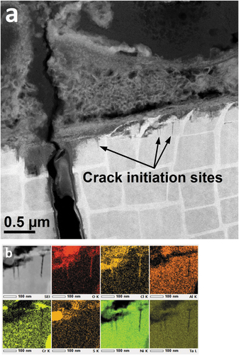
Thin lamellae specimens were FIB sectioned from the mid-point of cracks observed on the surface of the 10-minute exposure c-ring sample. All primary cracks were propagated on the (100) plane, passing through γʹ precipitates. Several short (<200 nm) cracks were measured, adjacent to the most significant primary cracks ()). These smaller cracks, <10 nm in width, also propagated on the (100) plane and each was nucleated and terminated within a single γʹ precipitate. EDS measurements revealed oxygen and chlorine in these diminutive cracks but although sulphur was detected at the crack opening, it could not be confirmed within the cracks themselves ()).
Figure 3. (a) HAADF-STEM image showing a primary crack, several crack embryos and a voluminous surface corrosion product, and (b) EDS maps of a γʹ precipitate, including surface corrosion and crack embryos.
Lift-out specimens were sectioned through prior salt-ring walls, from regions within the perimeter of the salt rings and from areas adjacent to salt rings. STEM-EDS analysis of the voluminous outer scale revealed a thin convoluted nickel oxide layer, regions of chromium oxide, aluminium oxide and an incomplete titanium enriched layer. Within voids formed in the porous oxide layer, chlorine enriched regions were observed, as was a sulphur-sodium-oxygen rich phase, possibly Na2SO4, even at this early stage, chlorine was largely dissociated from sodium.
Larger primary cracks exhibited thin layers of crystalline NiO on exposed surfaces toward the crack opening, although these layers were not easily detected at greater depths into the crack (). In addition to the NiO layer, a thin film of amorphous material, containing O-Cl-S, was observed between the outer NiO and crack surface. Within these amorphous channels, strands of sulphur rich, high-z, crystalline material were detected, often only a few nm thick.
Figure 4. (a) BF-STEM image showing a primary crack tip in a 10-minute exposure CMSX-4 c-ring and (b) the accompanying EDS maps revealing element distributions at the crack tip.
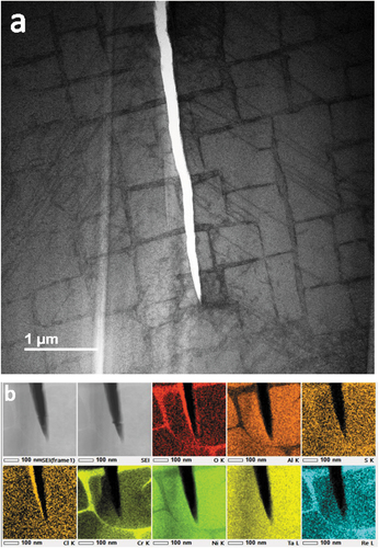
Analysis of primary crack tips ()) revealed numerous <011> traces of {111} type stacking faults in the γʹ precipitates adjacent to the crack. Dislocation densities were greatest in the γ matrix and a high density of dislocations was seen at the crack tip, although it is possible that the tip was in coincidence with a section of γ matrix, that lay in the plane of the FIB lamella.
EDS analysis at the absolute crack tip ()) revealed a thin film of oxygen and chlorine-enriched material; sulphur was not detected at the crack tip. On this occasion, it is possible that less O and Cl was apparent on the right hand edge of the crack, due to detector shadowing. However, clearly, Cl and O were detected at the tip of a 20 µm deep crack, at a point approximately midway along the crack length, beneath salt deposit features, after 10 minutes testing. At this stage, there was no evidence of crystalline NiO growth at the crack front but a film of amorphous Cl-O rich material was evident.
Crack analysis S/TEM: 2 hours exposure
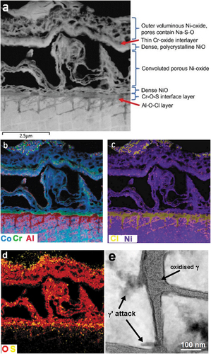
General corrosion, following 2 hours test exposure, in the vicinity of salt ring features, was comprised of an outer porous layer, made up of a skeletal network of nickel oxide, interspersed with Na2SO4 ()). Beneath this layer, a dense polycrystalline nickel oxide layer was observed, beneath which was a convoluted and porous (NiCo)O layer. A thin layer, approximately 200 nm in thickness, of chromium oxide/sulphate was detected at the original alloy surface and a thin Al-O-S layer was situated just beneath this, at the alloy/oxide interface. Corrosion of γ matrix channels, in the near surface region was observed to depths of approximately 2 µm, with only indications of the initial stages of γʹ attack apparent. Isolated sulphur-rich particles were detected in the chromia layer, at the alloy/oxide interface and occasional S-rich particles were seen in the corroded regions of γ and γʹ. Oxidation of the γ channels was dominated by oxygen, with chlorine and sulphur detected but to a lesser extent. However, STEM EDS analysis indicated the most prevalent oxidised species in the γ channel was aluminium, Ni and Re were also detected; yet only low concentrations of Cr and Co remained ()). The γ matrix network in these regions no longer displayed a continuous single crystal structure but was replaced by an array of polycrystalline nano-particles. Interestingly, in regions of γ attack, Al was measured with an even distribution across the γʹ precipitates and the corroding γ matrix channels, suggesting diffusion of Al, from the γʹ to γ channels.
Figure 5. (a) HAADF-STEM image of corrosion products in the vicinity of a salt ring feature. (b–d) EDS maps showing outward growth of porous and dense NiO layers above a chromium rich oxide/sulphate formed on the alloy surface and Cl-O attack of the γ matrix network and (e) HAADF STEM image showing oxidised γ matrix (2-hour test specimen).
The complex chemistry and morphology of salt-ring wall corrosion is presented in ). There were similarities between broad-front and salt-ring regions of attack, layers of porous convoluted, and dense polycrystalline NiO (, region 3) were observed. Oxygen was detected throughout the surface scale and within the corroded areas of the alloy ()). In contrast to the areas displaying broad front alloy attack, beneath the salt ring wall, γʹ was preferentially attacked; chlorine, oxygen and sulphur were all detected in this region. Both sulphur and chlorine were present in discrete regions of the salt ring wall ()), in beam-sensitive phases that appeared to be amorphous and each was detected in association with oxygen, nickel and cobalt (, regions 1 & 2 respectively).
Figure 6. (a) HAADF STEM image ( EDS locations indicated), EDS composite maps (b) & (c) showing the complex nature of the corrosion products in a prior salt ring wall and the preferential attack of γʹ. (2-hour exposure).
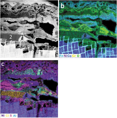
Table 2. Scale chemistry, atomic % (others = Al, Ti, Cr, Mo, Hf, Ta, W and Re).
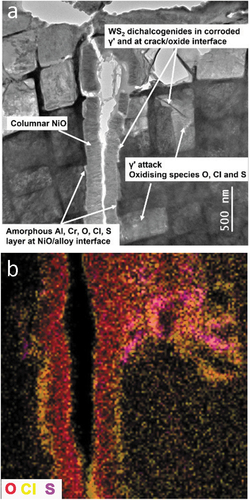
Regions of aluminium oxide, enriched in chlorine and tantalum, and areas of chromium oxide, also enriched in chlorine were observed at the crack opening. A columnar, polycrystalline nickel oxide core, down the centre of the crack, was formed by the growth of NiO layers on the opposing crack surfaces ()). However, a low-z amorphous layer was observed at the interface between the nickel oxide layer and the alloy-crack surface. Due to its deminutive size and stray EDS signal from surrounding material, it was not possible to determine the precise composition of the narrow low-z interface layer but oxygen and chlorine were routinely detected; sulphur was also detected in this interface layer and in adjacent regions of γʹcorrosion ()).
Figure 7. (a) BF-STEM image revealing a crack and the associated features and (b) the distribution of oxidising species and their relative locations.
High-resolution imaging revealed fine strands of layered material directly adjacent to surfaces of corroding γʹ material, situated within the amorphous interface layer between the columnar NiO and cracked alloy surfaces (). The majority of these features were only a few nm in width but often greater than 100 nm in length ()). Strands of high-z material were observed lining the surfaces of primary cracks, small secondary cracks and within corroded γʹ precipitates ()). EDS analysis indicated the layered structures were rich in sulphur and tungsten. Atomic resolution HAADF-STEM and BF-S/TEM lattice resolution images suggest that the crystal structure was consistent with a dichalcogenide phase (). Large numbers of dichalcogenide features were also observed at the γ/γʹ interface, where previous work has demonstrated an enrichment of tungsten [Citation8]. Orthogonal arrays of dichalcogenide films, aligned with the alloy <001> directions, were also prevalent in corroded γʹ material.
Figure 8. (a) BF-STEM image features common to primary and secondary cracks, (b) expanded BF-STEM view of a, and (c), BF-TEM image showing orthogonal arrays of MS2 films in a corroded γʹ precipitate (a & b 10 minute test and c, 2 hour exposure).
Figure 9. HAADF STEM image revealing the atomic structure of a dichalcogenide strand, with UVW [110] R3m:H model structure overlayed (COD 9012102).
![Figure 9. HAADF STEM image revealing the atomic structure of a dichalcogenide strand, with UVW [110] R3m:H model structure overlayed (COD 9012102).](/cms/asset/8b1b9d16-477c-4759-a9f2-ea3ea41047c1/ymht_a_2182587_f0009_c.jpg)
Given their diminutive dimensions and complications due to peak overlaps, chemical analysis was extremely challenging. However, quantification maps, produced using the JEOL EDS system indicate that the MS2 compounds were predominantly WS2. Point analysis, using the Oxford Instruments EDS system, provided supporting data, indicating the features are tungsten disulphides, with lesser concentrations of molybdenum and tantalum. It was assumed that the additional trace levels of O, Ni and Na that were detected arose from the amorphous material surrounding the MS2 feature.
Discussion
Under the current testing conditions, cracks were formed within the first 10 minutes of testing and on exposure to the burner-rig environment, crack surfaces were oxidised. The thickness of down-crack oxide increased at positions close to the sample surface and oxidation was less apparent at greater depths into the material, similar to the wedge-shaped oxidation, as reported by Chapman [Citation5]. Oxide scales situated above cracks, on the external c-ring surfaces were typically enriched in aluminium, but on occasion titanium and tantalum scales were also observed covering cracks. These three elements, Al, Ti and Ta, segregate preferentially to the γʹ phase, hence there appears to be a preferential attack of γʹ and an outward transport of its stabilising components to the c-ring surface.
The oxidation and corrosion layers formed on the freshly exposed crack surfaces, within 10 minutes, were thinner than those observed after 2 hours of testing. At this early stage, it was possible to gain a greater insight into the chemical species that might play a role in the mechanism responsible for cracking. The absence of sulphur from cracks formed within 10 minutes suggest it is not responsible for crack propagation, although it plays an important role in type II corrosion and pitting, which can lead to the nucleation and initiation of cracks. However, sulphur was detected repeatedly at crack tips after 2 hours exposure, hence down-crack diffusion is probable. In addition, dichalcogenides have been identified in all samples, very often as nm thick layers partially covering the exposed crack surfaces. Transition metal MS2 dichalcogenides (metal disulphides), where M is a single, or a mixture of more than one, transition metal species, were observed in both 10 minute and 2-hour test piece specimens. Fine strands of comparatively high-z features were identified in corroded regions of γʹ and along γ/γʹ interfaces in corroded material. Dichalcogenides were also, and possibly more importantly, observed at the metal/oxide interface of crack surfaces. The basal planes of dichalcogenides are bonded by Van der Waals forces, hence should sulphur play a role in the cracking mechanism, separation of these layers would require very little force.
Kim reports that about 40 different layered transmission metal dichalcogenide compound structures exist [Citation11]. MX2 dichalcogenides are a compound of M (a transition element) and X (a chalcogen element, S, Se and Te). Considering the CMSX-4 alloy elements and sulphur only, Ti, Mo, Hf, Ta, W, and Re will readily form MS2 compounds. It is also indicated that both Co and Ni are capable of forming dichalcogenides but not all have layered structures, e.g. NiTe2 is a layered compound, whereas NiS2 adopts a pyrite structure.
A correlation between increased volume fractions of γʹ and an alloy’s susceptibility to environmentally assisted cracking has been reported [Citation5]. Interestingly, tests were performed in the absence of NaCl, yet all precoated (Na2SO4/K2SO4) CMSX-4 alloy c-ring specimens bore cracks after testing at 450°C, 500°C and 550°C under a load of 700MPa and in an atmosphere of 50 ppm SO2 in flowing air. Therefore, it can be concluded that the environmentally assisted cracking of CMSX-4 single crystal alloy, as reported here, does not necessarily require the presence of chlorine. However, the presence of chlorine appears to have a profound effect on the time required to nucleate and propagate cracks, acting as an accelerant. In this work, chlorine was consistently observed in narrow concentrated regions at the alloy/oxide interface, in an amorphous compound with oxygen and metallic components. This was apparent in both primary cracks, secondary cracks and in pockets of γʹ attack, hence in the majority of cracks chlorine was detected, along with oxygen. Oxygen was detected in all cracks but caution should be applied, as the surfaces of FIB prepared surfaces are left in a highly active state and oxidation on exposure to air is expected [Citation12].
Work carried out by Zhu [Citation13] reports on the environmentally assisted cracking of a single crystal stainless steel (316 L), where cracks propagated along low energy {001} cleavage planes. In the presence of hydrogen, the free energy of formation, of {001} cleavage planes, was reduced by as much as 28%. However, crack propagation was further assisted owing to a 73% reduction in the free energy of surfaces due to the synergistic adsorption of both H and Cl atoms.
Although hydrogen was not intentionally introduced to the test environment, its presence can neither be ruled out, nor detected using the equipment at hand. However, during c-ring preparation, NaCl was applied in a H2O solution, hence residual moisture during testing is a distinct possibility. It also stands, that concentrations of residual moisture would be greatest in the vicinity of prior salt ring deposits, the very location in which cracks initiate and a reservoir of sub-scale chlorine is detected. Furthermore, although speculative, in the presence of residual moisture, nano-structured transition metal dichalcogenides could provide a source of atomic hydrogen, due to their electro-catalytic properties which have been extensively studied in the field of water splitting [Citation14].
Hydrogen embrittlement has been identified as a cause of environmentally assisted cracking of nickel alloys. In many cases, the proposed mechanism relates to the build-up and trapping of hydrogen which embrittles grain boundaries [Citation15], clearly this mechanism is not relevant to single crystal alloys, in the absence of grain boundaries. However, elastic distortion of a crystal lattice can provide a preferred location for hydrogen trapping, it is also feasible that such distortions, in addition to dislocations ()), might offer fast diffusion paths for atomic hydrogen. Potential causes of lattice distortion could be driven by mechanical load, compositional gradients at the atomic scale, or lattice strain due to the γ/γʹ misfit. Furthermore, Zhang [Citation16] has demonstrated, using both atomic simulations and ultra-high resolution STEM measurements, that permeated chlorine can induce lattice expansion along {001} crystal planes. This observation offers a potential explanation for the preferential segregation of hydrogen toward crack tips, on {001} planes and perhaps further evidence supporting Zhu’s observation of the combined effect of Cl and H, on the [001] cleavage fracture of single crystal 316 steel [Citation16].
Lortrakul et al. [Citation4] report an outer NiO layer, interspersed with CoO crystals is formed during the type II corrosion of CMSX-4 alloy, precoated with Na2SO4, in a controlled O2-SO2-SO3 atmosphere at 700°C. Internal attack of the γ phase was reported to a depth exceeding 5 µm after 15 minutes at 700°C with less extensive corrosion of the γʹ precipitates, due to their apparent slower corrosion rate. These findings contrast with the results reported here, although the conditions differ significantly, where in the presence of S and Cl, both γ and γʹ were attacked at a comparable but slower rates and in different areas of the c-ring. Brooking [Citation8] reported preferential attack of CMSX-4 γʹ precipitates, under sulphidating conditions where surfaces were in tension, in the same work it was observed that γ matrix channels were preferentially attacked on surfaces under compressive stress. It is likely that local variations in chemistry exist, particularly during the early stages of testing, and we have demonstrated that Cl concentration is greatest in sub-scale regions in the vicinity of salt ring corrosion, thus leading to preferential attack of the γʹ phase. It is important to note that crack initiation occurred in less than 10 minutes, under, or adjacent to salt-ring features, in the same regions where chlorine concentrations were at their greatest. Significantly, cracks appear to initiate in and propagate through γʹ precipitates, although obviously they must breach the γ network in order to propagate further. Therefore, it appears that chlorine plays a role in accelerating the nucleation stage of crack formation in single crystal CMSX-4 alloy.
Conclusions
Stressed c-ring test pieces, machined from a single crystal of CMSX-4® composition alloy, which were pre-coated with NaCl and exposed to 50 ppm SO2 in flowing air, at 550°C, formed cracks within 10 minutes. By increasing the test duration to 2 hours, cracks became more numerous and crack lengths and depths increased.
Cracks were nucleated and grew in vicinity of prior salt-deposit corrosion rings, where a reservoir of chlorine enriched material was identified in the sub-scale region, at the alloy/oxide interface.
An amorphous layer, containing oxygen and chlorine was observed down primary cracks, adjacent to the alloy surface, beneath an outer NiO scale. Layered tungsten disulphide dichalcogenide films were identified on cracked alloy surfaces, within the amorphous layer, and forming orthogonal arrays, parallel to the alloy <001> directions, in corroded γʹ precipitates.
Oxygen and chlorine were detected down the full length of 200 nm long cracks (crack embryos) observed after 10-minute exposure; each initiated, propagated and terminated within a single γʹ precipitate.
Sulphur and chlorine regularly detected in cracks but not always, whereas oxygen was always present.
Acknowledgments
We would like to thank both Rolls Royce plc and Cranfield University for funding and their invitation to take part in these studies.
The STEM and SEM experiments in this paper were performed in the Albert Crewe Centre for Electron Microscopy and the Scanning Electron Microscopy SRF, at the University of Liverpool, maintained and operated as a Shared Research Facility by the Faculty of Science and Engineering.
Disclosure statement
No potential conflict of interest was reported by the authors.
Additional information
Funding
References
- Simcoe CR. Pioneers in metals research–part VI: the invention of the single crystal jet engine blade. Adv Mater Processes. 2016;174:30.
- Simms NJ, Heikinheimo L, Encinas-Oropesa A, et al. Predicting type II hot corrosion in industrial gas turbines. 2003. Vol. 6, p. H046.
- Sumner J, Encinas-Oropesa A, Simms NJ, et al. Type II hot corrosion: kinetics studies of CMSX-4. Oxid Met. 2013;80(5):553–563.
- Lortrakul P, Trice RW, Trumble KP, et al. Investigation of the mechanisms of type-II hot corrosion of superalloy CMSX-4. Corros Sci. 2014;80:408–415.
- Chapman N, Gray S, Sumner J, et al. Stress Corrosion Testing of CMSX-4, CM247LC DS and IN6203DS Ni-base superalloys. Oxid Met. 2021;95(1):85–104.
- Chapman N, Gray S, Sumner J, et al. Mechanical stress effects on 550 °C hot corrosion propagation rates in precipitation hardened Ni-base superalloys: CMSX-4, CM247LC DS and IN6203DS. Oxid Met. 2022;97(3):261–279.
- Brooking L, Sumner J, Gray S, et al. Stress corrosion of Ni-based superalloys. Mater High Temp. 2018;35(1–3):120–129.
- Brooking L, Gray S, Dawson K, et al. Analysis of combined static load and low temperature hot corrosion induced cracking in CMSX-4 at 550°C. Corros Sci. 2020;163:108293.
- Burkholder PS, Thomas MC, Frasier DJ, et al. Allison engine testing CMSX-4 single crystal turbine blades and vanes. International Charles Parsons Turbine Conference; 1995; Newcastle upon Tyne: The Institute of Materials.
- Giannuzzi LA, Stevie FA. A review of focused ion beam milling techniques for TEM specimen preparation. Micron. 1999;30(3):197–204.
- Kim TH, Kim YH, Park SY, et al. Two-dimensional transition metal disulfides for chemoresistive gas sensing: perspective and challenges. Chemosensors. 2017;5(2): 15
- Stephenson LT, Szczepaniak A, Mouton I, et al. The Laplace project: an integrated suite for preparing and transferring atom probe samples under cryogenic and UHV conditions. PLOS ONE. 2018;13(12):e0209211.
- Zhu L, Li Y. Cleavage-dissolution assisted stress corrosion cracking under elastic loads. npj Mater Degrad. 2021;5(1):25.
- Wang F, Shifa TA, Zhan X, et al. Recent advances in transition-metal dichalcogenide based nanomaterials for water splitting. Nanoscale. 2015;7(47):19764–19788.
- Taji I, Hajilou T, Ebner AS, et al. Hydrogen assisted intergranular cracking of alloy 725: the effect of boron and copper alloying. Corros Sci. 2022;203:110331.
- Zhang B, Wang J, Wu B, et al. Unmasking chloride attack on the passive film of metals. Nat Commun. 2018;9(1):2559.