
 ?Mathematical formulae have been encoded as MathML and are displayed in this HTML version using MathJax in order to improve their display. Uncheck the box to turn MathJax off. This feature requires Javascript. Click on a formula to zoom.
ABSTRACT
A Ni-25Cr (wt.%) alloy coated with the salts and mixtures of these salts with an industrial coal ash was exposed to Ar-60CO2-20 H2O at 650 °C for 300 h. The alloy without any deposit developed a uniform internal oxidation zone (IOZ) and an external metallic nickel layer surmounted by a thin NiO scale. Salt deposits changed the scale constituents and morphology. Predominantly, a duplex scale of NiO over a Cr2O3 layer grew with an underlying IOZ containing large Cr-rich oxide precipitates. Under a deposit of ash plus salts, the basic reaction morphology was the same as in the gas-only case, but the oxide layer was non-uniform. Local voids were formed within the alloy beneath chloride plus ash deposits. Under ash with sulphates, the alloy formed both partially protected areas and non-protective multi-layered scales. Spherical ash particles were enveloped by NiO in both salt-ash deposits.
Introduction
Coal provides an enormous amount of cheap energy but releases significant quantities of greenhouse gases into the atmosphere, especially CO2 [Citation1]. Because of the global warming threat, reducing greenhouse gas emissions is now becoming urgent. An advanced technology – oxyfuel combustion – is proposed to facilitate CO2 sequestration [Citation2,Citation3]. The flue gas produced after combustion is highly corrosive, and conventional heat-resisting Fe-based alloys cannot survive. Hence, Ni-based alloys are considered because of their superior high temperature mechanical properties and corrosion resistance [Citation4,Citation5].
Besides the corrosive gas, solid species like chlorides, sulphate, and ashes can deposit on alloy surfaces, hence accelerating the corrosion process [Citation6,Citation7]. The accelerated corrosion behaviour of Ni-based alloys in the presence of chloride/sulphate salts has been reported in previous studies [Citation8,Citation9]. The reason for the accelerating oxidation is the active oxidation caused by chloride salts [Citation9,Citation10], and/or the low melting mixture formed due to the reaction of sulphate salts with oxides [Citation11,Citation12]. However, the synergistic effects of salts and ash mixture need to be studied.
This paper examines the corrosion behaviour of a Ni–25Cr model alloy, in CO2–H2O gases without and with deposits at 650°C. The effects of chloride salt, sulphate salt, and their mixtures with ash particles are studied.
Materials and experimental procedures
A Ni-25Cr (wt. %) model alloy was prepared by arc melting pure metals Ni (99.95%), and Cr (99.995%), under a protective Ar-5%H2 gas atmosphere, using a non-consumable tungsten electrode. The resulting alloy buttons were annealed for 50 h at 1100 °C under a flowing Ar-5%H2 (vol. %) gas for homogenisation. Only a small deviation (±0.3 wt. %) was found from the designed compositions of Ni-25Cr, confirmed by SEM-EDS analysis after homogenising.
The alloy was then cut into approximately 9 × 7 × 2 mm rectangles, and ground to a 1200-grit finish, followed by polishing to a 3-µm finish and then electropolishing in 15% hydrochloric acid. The purpose of electropolishing was to eliminate the work-hardened surface zone introduced during sample preparation. The grains of Ni-25Cr were elongated, with sizes ranging from hundreds of microns to several millimetres.
For the gas-only experiment, the sample coupon was laid on a ceramic crucible with one face up to the gas atmosphere, for comparison with subsequent experiments with salt deposits. The ceramic crucible was placed in a horizontal alumina reactor sitting inside a tube furnace for isothermal oxidation at 650°C, and exposed to flowing gases for 300 h. The reaction gas composition was Ar-60%CO2-20%H2O (vol. %) with a linear flow rate of 2 cm/s. Argon and carbon dioxide inputs were controlled by mass-flow controllers. Wet gases were generated by passing the argon and carbon dioxide mixture through a water bath to first produce an excess amount of water vapour, which was then partially condensed inside a distillation column at a temperature set to achieve the required water vapour concentration [Citation13]. The calculated equilibrium partial pressure of oxygen in the gas stream is 1.5 × 10⁻⁸ atm and carbon activity is 1.6 × 10⁻¹⁵ [Citation14] ().
Table 1. Equilibrium minority gas partial pressures (atm) and aC at 650 °C, 1 atm.
For salt-coated experiments, NaCl and KCl were dissolved in distilled water in a mass ratio of 1:1.25, corresponding to the lowest solidus temperature (657°C) [Citation14], while Na2SO4 and K2SO4 were in a mass ratio of 1:1 and were confirmed to be solid at the reaction temperature [Citation15,Citation16]. Each solution was sprayed onto preheated sample surfaces to cause evaporation of the water. The coated samples were weighed after spraying, to ensure the deposit was within the 2.5 ± 0.5 mg/cm2 range. The deposited samples were exposed in the same way as described above for the gas-only conditions. The chloride and sulphate salt experiments were carried out in different furnaces with the same settings to avoid contamination. Equilibrium gas pressures and carbon activity values, aC, were calculated [Citation14] for the cases with salts present, and the results are listed in .
For ash plus salt deposit experiments, the salt mixture was mixed with the Eraring ash (provided by industry, composition listed in ) in a weight ratio of 1:9. The resulting mixture was then put in ethanol to form a suspension. The suspension was applied to preheated specimens and dried on a hot pan. The coated samples were weighed to make sure salt + ash deposits were in the 30 ± 5 mg/cm2 range. The resulting coated samples were exposed in the same way as described above for the salts-deposited specimens.
Table 2. The compositions for Eraring ash (wt. %).
All reacted samples were cold-mounted in epoxy resin for metallographic preparation. Cross-sections of deposited specimens were prepared using water-free lubricant to avoid the dissolution of any salts in the products. Reaction products in cross-sections were observed and analysed by using optical microscopy (OM) and field emission scanning electron microscopy (FEI Nova NanoSEM 230 & 450) equipped with energy-dispersive X-ray spectroscopy (EDS; Bruker).
Results
Reaction products of Ni-25Cr without deposits
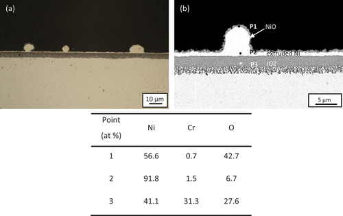
Cross-sections of Ni-25Cr after 300 h reaction without any deposit are shown in . As shown in the optical micrograph (), a scale consists of a uniform internal oxidation zone (IOZ) (~4 µm) with an outermost thin oxide layer (~0.5 µm) surmounting a metallic nickel layer (~1 µm) formed across the whole alloy surface. The constituents of the scale are revealed by the enlarged SEM image (). According to the point analysis results, the outer thin oxide layer is NiO (P1 in , with extruded Ni (P2 in below it, whilst the IOZ contains Cr-rich oxides (P3 in .
Figure 1. (A) Cross-sectional optical micrograph and (b) SEM image of Ni-25Cr after 300 h reaction in Ar-60CO2-20 H2O at 650°C.
Reaction products of Ni-25Cr with salts
Chlorides
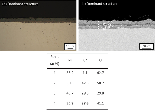
Chloride-coated Ni-25Cr after 300 h reaction formed two different oxide structures. Cross-sections of the predominant oxide structure (~70% of the whole surface) are shown in under the optical microscope and under the SEM, forming a multi-layered scale (~9 µm). This multi-layered scale consists of an outer thick NiO layer (~4 µm) (P1 in , and an intermediate Cr2O3 band (~0.9 µm) (P2 in . No detectable Na, K, or Cl was found by EDS analysis in the whole cross-section. The interface between NiO and Cr2O3 oxide is almost smooth across the alloy surface. Below the Cr2O3 layer, an IOZ containing Cr-rich oxides had formed (P3 and P4 in .
Figure 2. (A) Cross-sectional optical micrograph and (b) SEM image of 100 wt.% chloride salt covered Ni-25Cr (dominant structure) after 300 h reaction in Ar-60CO2-20 H2O at 650°C.
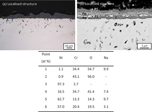
In addition, localised regions (~30% of the whole surface) of deep internal alloy attack (~25 µm) are seen (). The internal attack () produced a mixture of oxides and pores distributed deeply into the substrate (P5 and P6 in which was confirmed by both the SE image and the weak EDS signals (results not shown). A porous, external scale of Cr2O3 (~5 µm) (P2 in )) containing Ni particles (P3 in had grown on the surface. A considerable amount of Na was detected at both the outer surface and at the oxide–alloy interface (P1 and P4 in ). Moreover, a considerable amount of sodium was also detected in the void region (P5 and P6 in . However, neither potassium nor chlorine was detected. No detectable salts remained on the surface after reaction.
Figure 3. (A) Cross-sectional optical micrograph and (b) SEM image of 100 wt.% chloride salt covered Ni-25Cr (localised structure) after 300 h reaction in Ar-60CO2-20 H2O at 650°C.
Sulphates
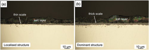
Optical images of alloy cross-sections after 300 h reaction at 650 °C under a sulphate deposit are shown in . Unlike the chloride deposit, the sulphate layer remained on the alloy surface after reaction. The alloy was partially protected by a thin scale after 300 h reaction, but this relatively protective region was limited to only a very small proportion (5%) of the surface. Most of the surface formed a relative thick scale under the sulphate layer as shown in . Under both thin and thick scales, a few internal precipitates with spheroidal shape were observed.
Figure 4. Cross-sectional optical micrographs of 100 wt.% sulphate salt covered Ni-25Cr after 300 h reaction in Ar-60CO2-20 H2O at 650°C.
More details are shown in BSE-SEM images (). In the protective-scale region, NiO islands (EDS point 1) were randomly distributed on the thin chromia, and a shallow internal oxidation containing small Cr-rich oxide precipitates (EDS point 2) had formed. The relatively thick scale covering most of the surface is seen to be multi-layered: NiO scale is formed immediately below the sulphate deposit, above a thin and continuous chromia layer (EDS point 5) with an IOZ beneath. Within this zone, large irregular chromium-rich oxides (EDS point 6) were found to be partially connected with the overlying continuous chromia layer, together with much finer oxide precipitates in the IOZ (EDS point 7). Below both the thin, protective scale and the thick multi-layered oxide scales, numerous Cr-rich sulphide particles (EDS points 3 and 8) were found beneath the IOZ.
Figure 5. Cross-sectional BSE-SEM images of 100 wt.% sulphate salt covered Ni-25Cr after 300 h reaction in Ar-60CO2-20 H2O at 650°C.
Reaction products of Ni-25Cr with salts + ash
Chlorides + ash
Two different oxide structures were also observed on Ni-25Cr after 300 h reaction in the presence of ash with 10 wt.% chloride salts (). The predominant structure (occupying ~90% of the whole surface) () is similar to the gas-only case, composed of an IOZ (~4 µm) with a metallic Ni layer (~2.5 µm) and a thin oxide layer (~0.3 µm) above it ().
Figure 6. (A) Cross-sectional optical micrograph and (b) SEM image of 10 wt.% chloride salt +90 wt.% ash covered Ni-25Cr (dominant structure) after 300 h reaction in Ar-60CO2-20 H2O at 650°C.
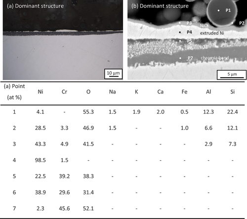
Figure 7. SEM-EDS mappings of 10 wt.% chloride salt +90 wt.% ash covered Ni-25Cr after 300 h reaction in Ar-60CO2-20 H2O at 650°C.
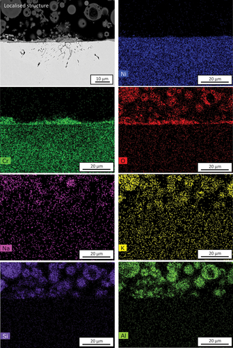
EDS-point analysis was carried out on this structure (). The results confirmed that the outer thin oxide is NiO (P3 in , with extruded Ni metal (P4 in below it. A Cr-rich IOZ was formed (P6 in , with a rather thick chromia band (P7 in at the reaction front. Local Cr-rich inner oxides were found beneath the Ni metal-IOZ interface (P5 in ). Moreover, both Na and K were detected within the ash particle (P1 in , and a layer of NiO was observed to have enveloped an ash particle (P2 in .
An example of the localised attack suffered by the alloy under the ash + chloride deposit is shown in . A relatively thick Cr2O3 (~4.5 µm) scale had formed and contained some encapsulated metallic nickel. Beneath this area of scale, subsurface voids are seen to penetrate up to 17 μm into the alloy. EDS-mapping analysis () confirms the existence of the outer Cr2O3 layer. Moreover, it should be noted that Na and K enrichment have occurred within the ash particles.
Sulphates + ash
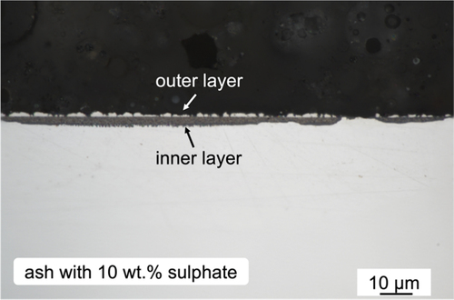
Cross-sectional optical image of the Ni-25Cr coated with ash +10 wt.% sulphate after 300 h reaction at 650 °C is shown in . The alloy formed both partially protective areas (20%) and a much greater amount of non-protective, multi-layered scales. Much more metallic Ni was extruded from the IOZ in the non-protective region.
Figure 8. Cross-sectional optical micrograph of 10 wt.% sulphate salt +90 wt.% ash covered Ni-25Cr after 300 h reaction in Ar-60CO2-20 H2O at 650°C.
The BSE-SEM image in shows a cross-section typical of the non-protective alloy corrosion developed under the ash + sulphate deposit. An internal oxidation zone had formed, containing a large volume fraction of fine precipitates near the surface and larger ones near the reaction front. Above the alloy surface, numerous metallic Ni (EDS point 1) islands had impinged to form an almost continuous layer. The outermost surface of these Ni islands was oxidised to form a thin Ni oxide layer (EDS point 3). Some ash particles were found in close contact with the outer Ni islands (the right side of , but others were encapsulated by a thin layer of NiO (EDS point 2).
Figure 9. Cross-sectional BSE-SEM images of 10 wt.% sulphate salt +90 wt.% ash covered Ni-25Cr after 300 h reaction in Ar-60CO2-20 H2O at 650°C.
Another area of non-protective corrosion is shown in , along with a region of thin protective chromia scale. The latter appeared to be continuous with a chromia band which had developed at the reaction front in the non-protective area. Although 10 wt. % sulphate was added into the ash deposits, no sulphides were found in the reaction products.
Discussion
The above results showed that in the gas-only condition, Ni-25Cr formed a more or less uniform oxide scale, consisting of an internal oxidation zone covered by a Ni layer with a thin NiO layer on the top surface (). Adding salts and/or ash deposits on the surface changed the oxide structure and morphology and produced non-uniform oxide scales as summarised in .
Table 3. Summarised oxide structure morphology on Ni-25Cr after 300 h reactions at 650 °C.
The presence of chloride/sulphate salts altered reaction morphologies significantly. There were two major oxide structures formed, with the dominant one consisting of an IOZ and outer NiO with a thin chromia layer in between (. The Ni layer observed in the gas-only condition was not seen in this situation. After 90 wt.% coal ash was added to the salts, a predominant structure with pure Ni layer () appeared, similar to that seen in the gas-only condition ().
The discussion will first examine the chloride and sulphate effects on oxide formation and morphology, and then the synergistic effect of chloride/sulphate salts and ash will be considered.
Effect of salts on oxide formation and morphology
The alloy without any deposit developed a uniform internal oxidation zone (IOZ) containing Cr-rich oxide and an external Ni layer with large scattered Ni nodules surmounted by a thin NiO scale. This reaction product morphology was typically observed in low-oxygen partial pressure, water-containing atmospheres [Citation17,Citation18]: metallic Ni was expelled from the IOZ to accommodate the growth of chromia precipitates, and the metallic Ni was slowly oxidised due to the retarding effect of H2O. Salt deposits on the sample surface dramatically changed the oxide-scale constituents and morphology.
In the present chloride and sulphate cases, two types of oxide structures were identified: a relatively thick multi-layered oxide scale covered most of the surface and a chromium-rich oxide scale developed in the remaining areas. The localised Cr2O3 layer was thick and relatively porous, containing some Ni particles with densely distributed subsurface voids in the chloride case (). In contrast, a thin Cr-rich oxide scale covered by scattered NiO islands was observed in the sulphate case ().
For the dominant thick multi-layered oxide scales, a much thicker IOZ, an intermediate chromia layer, and a continuous outer NiO layer were identified (). Despite the individual oxide thickness differences, the phase assemblage of these oxide scales could be written in general as an IOZ + intermediate Cr2O3 layer + outer NiO. The proposed diffusion path for this type of reaction product formation is plotted on the Ni-Cr-O phase equilibrium diagram at 650°C in (path b). For the alloy exposed to gas alone, the reaction products consisted of an IOZ, an intermediate Ni layer, and the external NiO and the diffusion path for this formation is also plotted (path a) in .
Figure 10. Schematic representation of Ni-Cr-O equilibrium phase diagram at 650°C with diffusion paths for (a) IOZ+pure Ni+NiO on Ni-25Cr without coating and (b) IOZ+chromia band+(spinel)+NiO with salt coating.
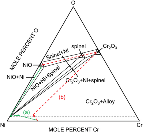
The scale constituents of IOZ with outer extruded Ni surmounted by NiO observed for the gas-only condition are seen to reach local chemical equilibrium across the reaction zone as shown by diffusion path (a) in . The difficulty arises in the phase assemblage for the salt coated alloy where a uniform NiO grows on top of a thin Cr2O3 layer. Considering the diffusion path from Cr2O3 to NiO domains, the spinel-phase NiCr2O4 is predicted to be involved. However, this phase was not found either by XRD or by cross-sectional observation. This might be because the expected spinel is too thin to be observed, or its formation is kinetically hindered by the relatively fast growth of NiO.
It is clear that the same alloy exposed to the same gas develops two different diffusion paths in the presence and absence of salts. This is only possible because salt constituents, Cl or S, participate in the reaction.
Effect of chlorides
In the situation of chloride salts, the so-called ‘Cl-induced active oxidation’ could have an effect. Chloride salts could react with the water vapour in the gas, forming Cl2, providing the condition for active corrosion to initiate [Citation9,Citation10,Citation19,Citation20]. Metal and metal oxides could react with Cl2 to form metal chlorides inside the oxide scale and/or in the internal region. The volatile chlorides can diffuse outward, to be reconverted to oxides as they approach the oxide–gas interface where the is higher. The released Cl2 can then participate in the active reaction again, forming loose, porous oxides, and even developing pores inside the alloys:
Here the forward EquationEquation 2(2)
(2) represents oxide volatilisation, favoured where
is higher, and the reverse reaction describes chloride re-oxidation and deposition externally where
is higher.
The possibility of Ni, Cr, and their oxides reacting with chlorine has been evaluated in the same reaction condition [Citation10]. We conclude that the volatilisation of Ni and NiO is negligible, but that of Cr and Cr2O3 can be significant when at the equilibrium Cr/Cr2O3 is used. When the volatile chloride reaches the alloy surface where
is high, it can be converted back to its oxide, and the thick, porous Cr2O3 layer is formed. Clearly, this chromia layer had little protective effect in retarding the continuation of chlorine attack or outward Ni diffusion to form NiO.
The way in which arrayed pores develop in the subsurface alloy region () is of interest. It has been found that intragranular carbides were formed within Ni-25Cr [Citation10] exposed to the same gas. Both Cr23C6 or Cr7C3 are thermodynamically favoured to react with Cl2, producing CO and the volatilised CrCl2, producing the observed voids.
The observation of Na, but not K, in the oxide scale and deeper in the subsurface pores () needs to be explained. The lack of potassium within the reaction zone is most likely the consequence of faster loss of potassium salt into the gas stream than that of sodium salt ( atm and
atm at 650°C). Nevertheless, mass transport within the alloy (of a Cl species inward and CrCl2 outward) ís required to support the dealloying process.
Further detailed analysis this subsurface region using FIB series sectioning of revealed that the observed pores are actually parts of continuous channels oriented towards the surface [Citation21]. These fine channels would provide transfer paths for the vapour species Cl2 and CrCl2, accounting for the dealloying reaction morphology and the absence of detectable Cl species in the solid residue.
The explanation for the presence of Na within the pores has not been definitively established. However, its colocation with oxygen and chromium suggests that material from the scale could have been transferred into the alloy pores during metallographic specimen preparation
Effect of sulphates
Both Na2SO4 and K2SO4 are expected to dissociate [Citation11]:
in which remains in the deposit and both O2 and S2 can react with the alloy. Gheno and Gleeson [Citation22] observed the Ni3S2-Ni eutectic under an outer NiO layer grown on pure Ni coated with Na2SO4 after exposure to air at 700 °C. Similar observations were found in the experimental results of Gregoire et al. [Citation23] in which the Ni3S2-Ni eutectic was found on pure Ni with Na2SO4 deposits after reaction in air at 700 °C. The formation of sulphides results from the dissociation of sulphates and penetration of S species through the NiO scale.
Our preliminary research [Citation12] found that Ni-25Cr beneath a sulphate deposit reacted at 750 °C in a CO2-rich, SO2-free environment formed internal chromium sulphides in the alloy matrix, even though quite a thick chromia band developed at the IOZ front. Evidently, the same process is in effect at 650 °C where numerous chromium-rich sulphides were found in front of the IOZ (). The S-containing species from sulphates must transport through the outer NiO scale, intermediate chromia band and IOZ to the alloy matrix and form sulphides. The presence of sulphur in the reaction systems adds a degree of freedom to the ternary Ni-Cr-O equilibrium system, affecting the phase assemblages as discussed above, and potentially altering transport mechanisms.
Chromia scales are well known to provide a slow-growing and protective barrier [Citation24]. Therefore, the significant thicknesses of outer NiO and bottom IOZ are surprising when a continuous chromia layer was observed at their interface. This could be rationalised by the involvement of S in transport within the oxides. At this low temperature, the diffusion of Ni and O would be mostly along the chromia grain boundaries, as also would be that of S [Citation25]. The absorption of S in Cr2O3 has been reported to affect its grain morphology and diffusion properties [Citation26], leading to a higher scaling rate. To pursue this question further, further investigation of the scale of morphological development with time is required.
Unlike the gas-only case, there was no nickel layer formed in the reaction zone developed by either salt-coated samples. All nickel had been converted to NiO. This difference indicates that the retarding effect of water vapour on Ni oxidation [][Citation18] was removed by the presence of salts, accelerating nickel oxidation. The possible reason could be due to the strong reaction/adsorption of water vapour with/by salts, which significantly reduces the water vapour retarding effect on NiO formation. Alternatively, preferential adsorption of S on the NiO surface and its grain boundaries could largely exclude uptake of water-derived species.
Effect of ash particles on Ni-25Cr corrosion
The typical reaction products for Ni-25Cr under a deposit of ash with 10 wt.% chloride or sulphate (30 5 mg/cm2) are NiO + extruded Ni + IOZ with or without a chromia band (). This is similar to that of the alloy without any salt deposit (NiO + extruded Ni layer or islands + IOZ, ). Although the amount of chlorides or sulphates is comparable to that under the salt only condition (2.5
0.5 mg/cm2), these oxide-scale constitutions were not the same as those in the salt-only condition discussed in section 4.1. Noting from that the extent of reaction is essentially the same in the gas-only and the two gas+ash+salt conditions, it is concluded that salt effects are largely in operative when the deposit contains mainly ash.
Solid ash particles were generally considered innocuous in the degradation of high-temperature alloys because of their rather stable chemistry and structure (mainly silica and alumina). Moreover, the re-appearance of the extruded Ni metal () indicates that the retarding effect of water vapour on NiO growth seen in the gas-only case is again in effect. The simplest explanation for the lack of salt effect on reaction morphology is that not enough salt contacts the surface to have the salt effect. Also the ash particles are loosely packed, allowing gas, including water vapour, to transport to the scale surface. Thus, the water vapour retarding effect on nickel oxidation can be maintained.
Although most of the reaction product had the same structure as in the gas-only condition, some local attack still appeared on the chloride + ash covered sample (). However, no sulphides were found in either the oxide scale or precipitated within the alloy in the sulphate + ash deposit case ().
The ‘wetting’ of ash particles by NiO was found on top of the outer scale when Ni-25Cr was deposited with ash + chloride or sulphate (). This is believed to result from accelerated NiO nucleation and growth along the surface of ash particles. Detailed analysis of this phenomenon is beyond the scope of this paper and will be published separately.
Conclusions
A model Ni-25Cr (wt.%) alloy coated with chlorides or sulphates and mixtures of these salts with an industrial coal ash (salt/ash weight ratio 10/90) was exposed in Ar–60CO2–20 H2O at 650 °C for 300 h. For comparison, the alloy without any deposit was also exposed to the same gas.
In the gas-only condition, Ni-25Cr alloy formed a uniform IOZ and an external nickel layer together with some nickel nodules surmounted by a thin NiO scale. The formation of this metallic nickel was attributed to the volume expansion from the IOZ because of Cr-rich oxide precipitation.
Salt deposits changed the scale structure and morphology and produced a non-uniform oxide scale. Predominantly, a duplex scale of NiO over a thin Cr2O3 layer with an underlying IOZ was found in both salt-coated samples after reaction. This phase assemblage was feasible, according to diffusion path analysis, only if an additional species (chlorine or sulphur) from the salt deposit is involved within the reaction zone. In the case of chloride salt, an active oxidation mechanism accounts for outward Cr transport and porous chromia layer formation.
In addition, local regions of non-uniform corrosion appeared slightly different in the two salts. In the presence of chlorides, local regions of the Cr2O3 scale contained encapsulated Ni metal with underlying subsurface alloy porosity. However, in the case of sulphates, scattered islands of NiO grew above a thin chromia layer, and little internal oxidation was evident. Internal S-rich precipitates developed within the alloy in all sulphate-coated samples. Although both S and Cl can pass through the chromia, they have different effects on its transport properties.
The disappearance of nickel layer in the case of salt-coated samples indicated that S and Cl each interacted with NiO surface and grain boundaries, interfering with the retarding effect of water otherwise observed for nickel oxidation.
Under a deposit of ash with 10 wt.% salts, the basic reaction morphology remained the same as under the gas-only case, but the oxide layer was non-uniform. This phenomenon is attributed to dilution by ash and greatly reduced salt-scale contact. As a result, the water vapour retarding effect on nickel oxidation is observed.
Acknowledgments
Financial support from the Australian Research Council’s Discovery Program is gratefully acknowledged.
Disclosure statement
No potential conflict of interest was reported by the authors.
Additional information
Funding
References
- Mintzer IM, Energy, greenhouse gases, and climate change. Annual review of energy. Annual Review of Energy. 1990;15(1):513–550.
- Ritchie H, Roser M, Rosado P, CO₂ and greenhouse gas emissions. Our world in data, 2020.
- Jordal K, Anheden M, Yan J, et al. Oxyfuel combustion for coal-fired power generation with CO2 capture—opportunities and challenges. Greenhouse Gas Control Technologies. 2005;7:201–209.
- Choe H, Dunand DC. Mechanical properties of oxidation-resistant Ni–Cr foams. Mater Sci Eng A. 2004;384(1–2):184–193.
- Zeng Z, Natesan K, Cai Z, et al. Effects of chlorine in ash on the corrosion performance of Ni-based alloys in a simulated oxy-fuel environment. Energy Fuels. 2018;32(10):10502–10512.
- Zeng Z, Natesan K, Cai Z, et al. Effect of coal ash on the performance of alloys in simulated oxy-fuel environments. Fuel. 2014;117:133–145.
- Okoro SC, Montgomery M, Frandsen FJ, et al. Time and temperature effects on alkali chloride induced high temperature corrosion of superheaters during biomass firing. Energy Fuels. 2018;32(7):7991–7999.
- McNallan M, Liang W, Oh J, et al. Morphology of corrosion products formed on cobalt and nickel in argon-oxygen-chlorine mixtures at 1000 K. Oxid Met. 1982;17(5–6):371–389.
- Grabke H, Reese E, Spiegel M. The effects of chlorides, hydrogen chloride, and sulfur dioxide in the oxidation of steels below deposits. Corros Sci. 1995;37(7):1023–1043.
- Cai Y, Nguyen TD, Zhang J, et al. Corrosion behaviour of Fe-based austenitic and Ni-based alloys in Wet CO2 gas with and without chloride deposits at 650° C. Corros Sci. 2023;210:110822.
- Pettit F. Hot corrosion of metals and alloys. Oxid Met. 2011;76(1):1–21.
- Xie Y, Cai Y, Zhang J, et al. Effects of sulphate deposits on corrosion behaviour of Ni-base alloys in wet CO2 gas at 750° C. Corros Sci. 2021;181:109227.
- Koutsoyiannis D. Clausius–Clapeyron equation and saturation vapour pressure: simple theory reconciled with practice. Eur J Phys. 2012;33(2):295.
- FactSage 8.1 Thermochemical Software and Database (accessed July 2022). 2022.
- Levin EM, McMurdie HF, Reser MK. Phase diagrams for ceramists: 1975 supplement. Columbus, Ohio: American Ceramic Society. 1975.
- Xie Y, Cai Y, Zhang J, et al. Effects of Sulphate Deposits on Corrosion Behaviour of Fe-Based Alloys in Wet CO2 Gas at 750° C. Oxid Met. 2021;95(1–2):23–43.
- Jiang C, Xie Y, Kong C, et al. Corrosion behaviour of Ni-Cr alloys in mixed oxidising gases at 650 °C. Corros Sci. 2020;174:108801.
- Xie Y, Zhang J, Young DJ. Water vapour effects on corrosion of Ni-Cr alloys in CO2 gas at 650 °C. Corros Sci. 2018;136:311–325.
- Cai Y, Nguyen TD, Zhang J, et al. Corrosion behaviour of Fe-25Cr alloy in wet CO2 gas at 650° C: effects of chloride deposits and Si+ Mn alloying addition. Corros Sci. 2022;195:110001.
- Aye KK, Nguyen TD, Zhang J, et al. Effect of silicon on corrosion of Fe-20Cr and Fe-20Cr-20Ni alloys in wet CO2 with and without HCl at 650° C. Corros Sci. 2021;179:109096.
- Cai Y, Effects of chloride deposit and coal ash on high-temperature corrosion of chromia-forming alloys. 2023, PhD Thesis, School of Materials Science and Engineering, Faculty of Science, University of New South Wales. UNSW. https://doi.org/10.26190/unsworks/24814.
- Gheno T, Gleeson B. On the Hot Corrosion of Nickel at 700 °C. Oxid Met. 2015;84(5):567–584.
- Grégoire B, Montero X, Galetz MC, et al. Mechanisms of hot corrosion of pure nickel at 700°C: influence of testing conditions. Corros Sci. 2018;141:211–220.
- Young DJ. High Temperature Oxidation and Corrosion of Metals, 2nd. Elsevier: 2016. doi:10.1016/B978-0-08-100101-1.00001-7.
- Zheng XG, Young DJ. High temperature corrosion of pure chromium in CO-CO2-SO2-N2 atmospheres. Corros Sci. 1994;36(12):1999–2015.
- Soltanattar S, Nowakowski P, Bonifacio CS, et al. Use of microanalysis to better understand the high-temperature corrosion behavior of chromium exposed to multi-oxidant environments. Oxid Met. 2019;91(1–2):11–31.