
Abstract
Single SAR image direct positioning is to determine the ground coordinate for each pixel in the SAR image assisted with a reference DEM. During this procedure, an iterative procedure is essentially needed to solve the uncertainty in elevation of each pixel in the SAR image. However, such an iterative procedure may suffer from the problem of divergence in shaded and serious layover areas. To investigate this problem, we performed a theoretical analysis on the convergence conditions that has not been intensively studied till now. The Range-Doppler (RD) model was simplified and then the general surface is degenerated into a planar surface. Mathematical deduction was then carried out to derive the convergence conditions and the impact factors for the convergence speed were evaluated. The theoretical findings were validated by experiments for both simulated and real scenarios.
1. Introduction
Single SAR image positioning is to determine the ground coordinate for each pixel in the SAR image assisted with an external DEM, which is widely used in the SAR ortho-image generation, multibaseline InSAR, stereoSAR, and so on. (Cheng Citation2004; Jiang Citation2012; Toutin Citation2004) SAR image positioning could be realized through either direct or indirect method (Cheng Citation2004; Jiang Citation2012). The indirect method starts from the ground coordinates of DEM resolution cells to solve the corresponding image coordinates, and it is currently the most widely used geocoding method as it does not require the iterative procedure. The direct method, which goes in the opposite direction, is to calculate the ground coordinate from the image coordinate of every pixel (Toutin Citation2004; Zhang Citation2013). During the direct positioning process, due to the uncertainty of the elevation of each pixel in the SAR image, an iterative procedure is needed, which suffers from the problem of divergence in shaded and serious layover areas (Cheng Citation2004; Yang et al. Citation2006). As a good supplement to the indirect method, the direct method has explicit geometric significance which could be helpful to study the geometric meaning of the rigorous imaging model of the SAR image and develop the multi-image positioning method (Cheng and Zhang Citation2012; Cheng et al. Citation2012, Citation2013). In the optical photogrammetry area, Sheng (Citation2005) has given the convergence condition of direct method through theoretical analysis, while the convergence condition suitable for SAR images have not been intensively studied by now.
Similar to the collinearity equations in photogrammetry (Zhang and Zhang Citation1996), Range-Doppler (RD) model is the rigorous imaging geometry model for the SAR image relating the image coordinates with the ground coordinates, which was first proposed by Brown (Citation1981) and developed by Curlander (Citation1982). In this paper, we borrow some ideas from optical photogrammetry and derive the convergence condition for single SAR image direct positioning based on a simplified RD model, which can help us evaluate the applicability of the algorithm. Also with the known terrain conditions, the iteration convergence condition can be used to predict the divergent areas. With the theoretical analysis, we can also sort out factors that affect the convergence rate, especially the initial elevation. These theoretical results are tested with various scenarios of simulated or true slopes.
2. Theoretical analysis of convergence condition
In order to theoretically analyze the convergence conditions, the RD model is simplified and then the general surface is degenerated into a planar surface. Mathematical deduction is carried out to derive the convergence conditions and the impact factors for the convergence speed are analyzed.
2.1. Basic principle for direct single SAR image positioning
For a particular image pixel, we use the RD model to calculate its ground coordinates with the given initial elevation, interpolate its height in the georeferenced DEM data and then update the initial elevation with the interpolated one. This procedure is repeated until the elevation difference between the two adjacent iterations is less than a certain threshold, and then the three-dimensional ground coordinates of the pixel are determined. However, as an iterative algorithm, it inevitably suffers from the divergence problem, especially in the areas with steep terrain. Suppose the position vector of satellite is RS = (XS, YS, ZS)T, the corresponding velocity vector is VSC = (Xv, Yv, Zv)T, and the position vector of the ground target T in the ground orthogonal coordinate system of geocentric space is RTC = (XT, YT, ZT)T, which satisfies the earth ellipsoid equation (Equation (Equation1(1) )).
(1)
where Rp is the earth ellipsoid polar radius; Re is the earth ellipsoid equatorial radius; HT means the elevation of ground target T and it changes with the position coordinates of target T (XT, YT, ZT) that is HT = f (XT, YT, ZT). If the target point T at the surface of the earth, then HT equals 0 m; and parameters Rp and Re are determined by the specific ellipsoid model.
Every pixel in the SAR images can be indexed by column j and row i. The azimuth slow time tij when the radar signal arrives at the ground target can be determined by tij = i·δta, where i is the row number and δta means the imaging time of each line in azimuth direction. In Equation (Equation2(2) ), R (i, j) means the distance between satellite and ground target at the moment tij. Equation (Equation3
(3) ) makes use of the Doppler information at the moment tij (Cheng Citation2004; Sekhar, Kumar, and Dadhwal Citation2014). The received radar signal suffers from Doppler Effect due to the non-orthogonal angle between the flight direction and echo direction. The Doppler frequency fd can be acquired through the meta data of the SAR image. Here in our experiment, we use the TerraSAR data which have been zero-Doppler processed and hence fd = 0. Equations (Equation1
(1) )−(Equation3
(3) ) comprise the RD model together (Cheng Citation2004; Sekhar e tal. Citation2014).
(2)
(3)
There are four unknown variables in above equations which are the position coordinates of target T (XT, YT, ZT) and its height HT, but there are only three equations to solve. Therefore, an iterative procedure is needed. As shown in Figure , it is a zero Doppler profile and the “S” represents where the SAR satellite is. Using a given initial elevation , we can determine the position coordinate of the initial projected point A1 (
,
,
) in the object space by Equations (Equation1
(1) )–(Equation3
(3) ). Next, vertically trace from A1 to surface point B1, and interpolate its height
from the DEM using the planar position coordinates of A1. Update HT with
and then use Equations (Equation1
(1) )–(Equation3
(3) ) to solve the projected point A2 (
,
,
). And then repeat the same procedure to determine subsequent projected points A2, A3, A4, … , An until An is convergent to target point T. Finally, output the position vector of An as the ground coordinates of T. If the target T loactes at profile of back-radar slope, the projected points A1, A2, … , An approach point T from both sides (as shown in Figure (a)), while if it locates at Profile of toward-radar slope, the projected points A1, A2, … , An approach point T from only one side (as shown in Figure (b)).
Figure 1. Iterative positioning method. (a) Profile of back-radar slope; (b) Profile of toward-radar slope.
2.2. Analysis of the iterative procedure
It is difficult to analyze the convergence condition on the general surface. In order to make the theoretical analysis easier, in this paper we first simplify the RD model, then discuss the convergence condition and further derive the convergence speed on planar surface, and finally analyze those on general surface. Figure shows a zero Doppler plane orthogonal to the satellite flight direction. S is the sensor, T is the ground target, and the flight direction of sensor is perpendicular to the paper inwardly. MA1 represents the earth ellipsoid surface and MT represents the simulated slope. In order to facilitate the modeling analysis, we assume S as the origin of the local coordinate system, where x is the direction from sensor S to Earth ellipsoid center O, z is the flight direction of the satellite, and y completes the right hand system S-xyz.
Figure 2. Simplification of the RD model. (a) Back-radar slope; (b) Toward-radar slope.
The RD model can be simplified in three aspects. First, MA1 can be viewed as line segment MA1 because its length is relatively very short compared with the distance between Earth center O and the first projected point A1. Second, A1A2 can be replaced by line segment A1A2 because calculation for actual data shows that length of A1A2 is relatively very short compared with the distance between the sensor S and A1. Third, is viewed as a right angle due to the same reason as in the second assumption above.
In order to validate the model simplification, we select the pixel located in the 10th row and 10th column in Spotlight TerraSAR-X image of Mount Song area acquired on 25 September 2011. According to the calculation, we can obtain MA1/OA1 = 0.0000386, A1A2/SA1 = 0.000247, . Suppose
and θ represents the radar depression angle. For the back-radar slope, there is
(as shown in Figure (a)); for the toward-radar slope,
(as shown in Figure (b)).
Convergence on the planar terrain surface is analyzed from the viewpoint of geometry. Suppose the distance between T and the nth projected point An is dn and β represents the slope angle in zero-Doppler plane.
For the back-radar slope, ,
, d2 = d1 tan β/tan γ, d3 = d2 tan β/tan γ, and so on. In a general form, dn = dn–1 tan β/tan γ = d1(tan β/tan γ)n–1. Hence, d1, d2, d3, … , dn is a geometric sequence with ratio of tan β/tan
According to the convergence condition of geometric sequence, it is easy to obtain.
(4)
If the geometric sequence is convergent, A1, A2, … , An approaches T gradually. Hence, the sufficient and necessary condition for convergence is β ≤ γ. Also
. Finally, the convergence condition for back-radar slope is
.
For the toward-radar slope, ,
,
,
and so on. In a general form,
. Hence, d1, d2, d3, …, dn is a geometric sequence with a positive ratio of
. According to the convergence condition of geometric sequence, we can obtain
(5)
If the geometric sequence is convergent, A1, A2, …, An approaches T gradually and iteration is convergent. Hence, the sufficient and necessary condition for convergence is
. Also
. Finally, the convergence condition for toward-radar slope is
. When the sum of the slope angle and the depression angle is greater than
, that is
, the layover is generated. Hence, the non-layover areas are convergent.
For back-radar slopes, , we can assume
; for toward-radar slopes,
, assume
. Then
fits for both back- and toward-radar slopes. When the iteration is convergent, assume the convergence threshold is ΔG and dn <ΔG. The initial elevation is
and the actual elevation for target T is
. We may assume
and derive n by solving this following equation.
(6)
where [x] is the truncation function which means taking the smallest integer greater than x. According to Equation (Equation6(6) ), the convergence speed is influenced by slope angle β in zero Doppler plane, the radar depression angle θ, convergence threshold ΔG and initial elevation
.
3. Experiments
3.1. Experiments on planar surface
The experimental data used was a TerraSAR-X Spotlight image of Mount Song area acquired on 25 September 2011. We randomly selected a pixel with line and column number (10, 10) and set the initial elevation and θ = 61.038°. Assuming a planar surface with different slope angles for the specified pixel (10, 10), an iterative positioning process is implemented. If convergent, the iterations and the final elevation that the iteration converges to were recorded. The sum of the slope angle and the depression angle were calculated and compared with π/2. If it was greater than π/2, the iteration process will be divergent according to the theoretical convergence condition. The toward- and back-radar slopes were tested differently.
As indicated by the results in Table , the iteration convergence can be achieved only when the slope angle and depression angle satisfy the deduced convergence condition. The theoretical analysis and experimental results agree with each other perfectly. The iterations required for convergence increase with the slope angle. Generally when the slope angle in the zero Doppler plane is about 30°, the convergence speed will be very slow. The initial elevation in these experiments is set to 0 m, that is HT(0) = 0 m. In fact, initial elevation has a great influence on the convergence speed. Taking the back-radar slope with slope angle of 10° as an example, the pixel selected in the TerraSAR-X image is still (10, 10) and its elevation converges to 38.622 m.
Table 1. Experimental results of a planar surface.
As shown in Figure , the height range 0–200 m are divided by interval of 10 m and every number of this sequence is set to be the initial elevation for iteration in this experiment. We can see that when the initial elevation is 40 m, the convergence speed is the fastest. Likewise, 37–40 m are divided by interval of 0.1 m and when the initial elevation equals 38.6 m, the convergence speed is the fastest; and then the height range 38.61–38.63 m are divided by interval of 0.001 m and when the initial height are set between 38.619 and 38.626 m, the convergence speed is the fastest. The experimental results show that the closer the distance between the initial elevation and the final elevation that the iteration converges to, the faster the convergence speed is.
Figure 3. Relationship between initial elevation and convergence speed.
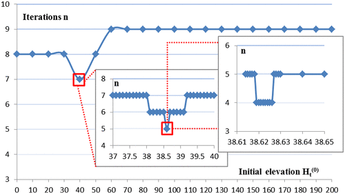
It can also be seen in Figure , when the initial elevation is larger than 60 m (until 200 m), the convergence speed is stable and slow. That is to say, if the initial elevation differentiates substantially from the final converge to elevation, the convergence speed will be slow and stable. When we know nothing about the true elevation, we can set the initial elevation as zero m, which would not have much impact on the convergence speed.
3.2. Experiments on general surface
The experimental data included a Stripmap mode TerraSAR-X image of Mount Song area acquired on 18 July 2011 and a reference DEM with the resolution of 3 m covering the same area. In this experiment, 20 typical feature points are chosen to test the theoretical convergence condition, including ten points for toward-radar and ten for back-radar slopes, respectively. The experimental results were shown in Tables and , where the slope angle and look angle of each sample points were calculated to test if the theoretical prediction meets the real iteration results. Also the screenshot of each sample point is obtained and the red stars represent the sample points, which show the terrain conditions (flat, layover, or shaded place) of the sample points directly.
Table 2. Experimental results of back-radar slope points.
Table 3. Experimental results of toward-radar slope points.
3.3. Analysis of experimental results
| (1) | If the iteration is convergent, for back-radar slope, the projected points A1, A2, … , An approach the ground point T from two sides; for toward-radar slope, the projected points approach T from one side. | ||||
| (2) | For the general surface, iteration is divergent in layover and shaded areas. In layover areas, multiple points on the ground become one point in the SAR image and hence when iterating, the projected points oscillate and cannot converge to the ground target T. In shaded areas, echo signal information is inadequate. From the other side, the slope angle is greater than the depression angle in shaded areas. For TerraSAR-X data, the depression angle is about 60° and the sum of the slope angle and the depression angle is obviously greater than 90° which does not meet the convergence condition derived above. | ||||
| (3) | The general surface is varied and rolling and it is very different from the simulated planar surface. Therefore, the theoretical convergence condition cannot fit for every ground point. Also the iteration process is limited by the resolution of the auxiliary DEM. | ||||
4. Conclusions
When geocoding a single SAR image with a DEM, for simplified planar surface, the convergence of iteration is depended on both the slope angle and the depression angle. The convergence speed is determined by the depression angle, the slope angle, convergence threshold, and initial elevation. The closer the distance between the initial elevation and the true elevation, the faster the iteration converges. When the initial elevation deviates a lot from the true elevation, the convergence speed will be slow and stable. When the true elevation of ground target is unknown, it is reasonable to set the initial elevation as 0 m.
The simplification of the RD model is reasonable which is verified by the experiment. Hence, it can be used to deduce the convergence condition. The experiment results of a planar surface fit well with the theoretical convergence condition, which validate the theoretical findings. For a general surface, the divergent points occur mainly in the layover and shaded areas as the theoretical analysis has expected. However, it cannot be guaranteed that the convergence of all the points is consistent with the theoretical prediction because the general surface is complicated and projected points A1, A2, … , An fall on different slopes while the convergence condition is deduced based on the planar surface.
As for the general ground surface, the convergence condition can also be used by dividing the complicated general surface into small locally flat grounds, in which the convergence condition should be the product of convergence conditions with different slope angles and depression angles.
Funding
This work was supported by the National Natural Science Foundation of China [grant number 41271457] and the Demonstration System of High Resolution Remote Sensing Applications in Urban Fine Management Area [grant number 06-Y30B04–9002-13/15].
Notes on contributors
Yuting Dong is a PhD candidate of LIESMARS, Wuhan University. Her research interest is the geolocation of high resolution SAR images and radargrammetry.
Lu Zhang is Professor of LIESMARS, Wuhan University. His research focuses on radar interferometry, radargrammetry, and geolocation of high resolution SAR images.
Mingsheng Liao is Professor of LIESMARS, Wuhan University. He is mainly engaged in time-series InSAR and their applications in topography, geological hazard monitoring, infrastructure security etc.
Acknowledgments
The authors would like to thank the German Aerospace Center (DLR) for providing the test data-sets via the DLR AO LAN0793 and LAN0634, and Prof. Miaozhong Xu of LIESMARS for providing the photogrammetric DEM with spatial resolution of 3 m.
References
- Brown, W. E. 1981. “Applications of SEASAT SAR Digitally Corrected Imagery for Sea Ice Dynamics.” Proceedings of American Geophysics, Baltimore, Maryland, USA, 25–29.
- Cheng, E. X. 2004. Study on Ortho-rectification Methodology of Space-borne Synthetic Aperture Radar Imagery. [ In Chinese.] Beijing: Chinese Academy of Forestry.
- Cheng, C. Q., and J. X. Zhang. 2012. “Rigorous Positioning with Side-looking Radar Imagery Based on Range-coplanarity Model.” Journal of Remote Sensing 16 (5): 881–894.
- Cheng, C. Q., J. X. Zhang, K. Z. Deng, and L. Zhang. 2012. “Range-coplanarity Equation for Radar Geometric Imaging.” Journal of Remote Sensing 16 (1): 38–49.
- Cheng, C. Q., J. X. Zhang, G. M. Huang, and L. Zhang. 2013. “Range-cocone Equation with Doppler Parameter for SAR Imagery Positioning.” Journal of Remote Sensing 17 (6): 1444–1458.
- Curlander, J. C. 1982. “Location of Space-borne SAR Imagery.” IEEE Transactions on Geoscience and Remote Sensing 20 (3): 359–364.10.1109/TGRS.1982.350455
- Jiang, H. J. 2012. “High-Resolution Spaceborne SAR Interferometry for DEM Generation and Updating.” [ In Chinese.] PhD thesis, Wuhan University.
- Sekhar, K. S. S., A. Kumar, and V. K. Dadhwal. 2014. “Geocoding RISAT-1 MRS Images Using Bias-compensated RPC Models.” International Journal of Remote Sensing 35 (20): 7303–7315.10.1080/01431161.2014.968266
- Sheng, Y. W. 2005. “Theoretical Analysis of the Iterative Photogrammetric Method to Determining Ground Coordinates from Photo Coordinates and a DEM.” Photogrammetric Engineering & Remote Sensing 71 (7): 863–871.10.14358/PERS.71.7.863
- Toutin, T. 2004. “Review article: Geometric Processing of Remote Sensing Images: Models, Algorithm and Methods.” International Journal of Remote Sensing 25 (10): 1893–1924.10.1080/0143116031000101611
- Yang, J., B. Pan, D. R. Li, and Y. Z. Zhong. 2006. “Location of Spaceborne SAR Imagery without Reference Points.” [ In Chinese.] Geomatics and Information Science of Wuhan University 31 (2): 144–147.
- Zhang, H. M. 2013. “Research on Technologies of Accurate Positioning with SAR images.” PhD thesis, PLA Information Engineering University.
- Zhang, Z. X., and J. Q. Zhang. 1996. Digital Photogrammetry. [ In Chinese.], 76. Wuhan: Wuhan Technical University of Surveying Science and Technology Press.