
 ?Mathematical formulae have been encoded as MathML and are displayed in this HTML version using MathJax in order to improve their display. Uncheck the box to turn MathJax off. This feature requires Javascript. Click on a formula to zoom.
ABSTRACT
Dead Reckoning is a relative positioning scheme that is used to infer the change of position relative to a point of origin by measuring the traveled distance and orientation change. Pedestrian Dead Reckoning (PDR) applies this concept to walking persons. The method can be used to track someone's movement in a building after a known landmark like the building's entrance is registered. Here, the movement of a foot and the corresponding direction change is measured and summed up, to infer the current position. Measuring and integrating the corresponding physical parameters, e.g. using inertial sensors, introduces small errors that accumulate quickly into large distance errors. Knowledge of a buildings geography may reduce these errors as it can be used to keep the estimated position from moving through walls and onto likely paths. In this paper, we use building maps to improve localization based on a single foot-mounted inertial sensor. We describe our localization method using zero velocity updates to accurately compute the length of individual steps and a Madgwick filter to determine the step orientation. Even though the computation of individual steps is quite accurate, small errors still accumulate in the long term. We show how correction algorithms using likely and unlikely paths can rectify errors intrinsic to pedestrian dead reckoning tasks, such as orientation and displacement drift, and discuss restrictions and disadvantages of these algorithms. We also present a method of deriving the initial position and orientation from GPS measurements. We verify our PDR correction methods analyzing the corrected and raw trajectories of six participants walking four routes of varying length and complexity through an office building, walking each route three times. Our quantitative results show an endpoint accuracy improvement of up to 60 when using likely paths and 23
when using unlikely paths. However, both approaches can also decrease accuracy in certain scenarios. We identify those scenarios and offer further ideas for improving Pedestrian Dead Reckoning methods.
1. Introduction
Indoor positioning systems (IPS) can be used to locate devices and their users in buildings, thus enabling the use of location-based services. These may include navigation, tracking, or point of interest alerts. While these services can be provided outdoors using GPS (which is available in nearly all modern smart devices), inside and near buildings, GPS localization is unreliable or even unavailable.
Smart mobile devices, e.g. smartphones and wearables, are equipped with inertial sensors and a multitude of radio technologies, that can be used to locate the device. There are two basic approaches: infrastructure-based methods use, e.g. Wifi, Bluetooth, or Near-Field-Communication beacons at fixed positions in the building to calculate a device’s position based on the received signal strengths of those beacons. These methods can achieve up to meter-accurate results, but require a relatively dense population of beacons throughout the building and are highly dependent on the building's architecture: increasing number and irregularity of walls can distort the radio signal characteristics and decrease positioning accuracy.
The second approach uses a fixed, known starting point of the device (e.g. the building entrance) and calculates the position based on the aggregated movement since the starting point. This method is called Pedestrian Dead Reckoning (PDR). Main concerns regarding PDR are the errors introduced through the sensing mechanisms. Typically, accelerometers and gyroscopes are used to calculate the user’s path. However, sensor drift and other accumulated errors will quickly deteriorate the accuracy the farther away the user walks. Methods are required to re-adjust the estimated position to the physical environment.
Here, hybrid approaches come into play: these methods combine the first two approaches. Typically, the PDR results are corrected using infrastructure information when they are most reliable. This eliminates many of the disadvantages of the two approaches, but still requires a setup, configuration, and learning of the used infrastructure.
Another important factor for the accuracy of PDR systems is the quality of the initial position and orientation. Without correction mechanisms, an initial localization error propagates to the endpoint. Naturally, a person is outdoors before entering a building, i.e. before starting indoor localization. Therefore, an obvious method is to use satellite navigation to determine the last position before entering a building. However, the accuracy of GPS greatly decreases in the vicinity of buildings, especially tall buildings. An error of 3 m in an open area increases to more than 20 m in an urban canyon, as shown by Modsching, Kramer, and ten Hagen (Citation2006). In addition, the time of signal loss can differ greatly from the actual time of entry. While massive, multi-storey buildings quickly interfere with the GPS signal, glass facades have a much lesser effect on signal quality.
In this paper, we propose the use of building map data to improve localization accuracy. We demonstrate our approach in an IPS that uses a foot-mounted inertial sensor, a simple Madgwick filter-based step detection, as well as step heading and length estimation. Our algorithms can be applied to most existing PDR and hybrid systems regardless of sensor location and device positioning method, as long as the PDR uses a step-based path estimation method. Additionally, we present a method to determine the initial position and orientation with a combination of PDR and GPS.
The paper is structured as follows: Section 2 describes related work, especially regarding PDR systems using foot-mounted sensors. Following, we present our basic indoor localization system and PDR approach in Section 3. Our proposed map-based correction methods are detailed in Section 4. The scheme to derive initial orientation and position from GPS measurements and PDR is described in Section 5. In order to evaluate these methods, we performed experiments that are described in Section 6 and evaluated in Section 7. Conclusions are then drawn and future work outlined in Section 8.
2. Related work
A comprehensive survey of PDR research is presented by Harle (Citation2013). In the paper, the author classifies PDR into two basic approaches: Inertial Navigation Systems utilize the estimated 3D trajectory of an inertial sensor to calculate the pedestrian's position, whereas Step-and-Heading Systems (SHS) first detect steps and then estimate each steps length and heading. The accumulation of all steps results in the estimated position. Examples for both approaches using various sensor setups and positions are given in the survey. Classified according to the survey, in this paper, we propose an SHS using a foot-mounted accelerometer and gyroscope for both step detection and length/heading estimation. We use raw acceleration/rotation values and no particle filter.
Using foot-mounted sensors for PDR is quite common, even though this sensor placement seems impractical today, as criticized by Harle (Citation2013). But as this sensor placement is advantageous for step detection and length/heading estimation, it is often used in SHS. The quality of the length and heading estimation is enormously important for the localization effort and has thus been subject in several papers, e.g. Bebek et al. (Citation2010); Foxlin (Citation2005); Castaneda and Lamy-Perbal (Citation2010); Bird and Arden (Citation2011). The computation of error propagation in an SHS and the incorporation of various sensors to limit error growth have also been the subject of past research as published by Jiménez et al. (Citation2010); Romanovas et al. (Citation2012); Olsson, Rantakokko, and Nygårds (Citation2014).
An open source foot-worn device for PDR by SHS is presented by Nilsson, Gupta, and Händel (Citation2014). The device features four inertial measurement units (IMU) to limit stochastic measurement errors and features onboard computation of step vectors and error estimates. A detailed analysis of an adaptation of this approach is given by Gupta, Skog, and Händel (Citation2015). The authors argue that such a multi-IMU SHS is capable of localizing a pedestrian in a radius of 4 m with 95% certainty after a 100 m walk under realistic conditions.
The precise computation of step length and heading necessitates the accurate tracking of the sensor orientation in relation to the global coordinate system. A straightforward approach to track the device orientation is the integration of the angular velocity. However, the drift inherent to gyroscopic measurements will soon lead to significant error in orientation and therefore heading estimation. This can be mitigated by using additional sensors such as an accelerometer or a magnetometer as shown by Sabatini (Citation2011). A popular approach to fuse multiple sensor readings into an attitude estimation is the Kalman filter (Lefferts, Markley, and Shuster (Citation1982); Sabatini (Citation2006); Bird and Arden (Citation2011); Cavallo et al. (Citation2014)). The Madgwick filter is a more recent development and is shown to provide results of comparable accuracy at reduced computational cost as demonstrated by Madgwick, Harrison, and Vaidyanathan (Citation2011). Indeed, Cavallo et al. (Citation2014) show an eighteen-fold reduction of computation time for one estimation cycle at similar heading accuracy on an STM32F3 micro-controller.
An SHS with stance detection utilizing only the angular velocity in the lateral axis of a foot-mounted sensor node is presented by Huang, Liao, and Zhao (Citation2010). This approach requires knowledge of the relation of the user frame of reference and the sensor frame. We argue that an approach which is agnostic to the sensor attachment orientation is more robust and therefore preferable. A study comparing acceleration and angular rate energy based stand detection is presented by Skog et al. (Citation2010). The authors find that an angular rate energy-based detector outperforms acceleration-based detectors. Olivares et al. (Citation2012) present a wide variety of stance detection methods for inertial data of body-worn sensors. The authors recommend a combination of acceleration magnitude and angular rate energy observation for stance detection with low delay and low computational complexity. Our adoption of this approach is described in detail in Section 3.
In our paper, we utilize map data to gather information on likely and unlikely paths. Both principles have been explored using different approaches before.
Xiao et al. (Citation2014) introduce MapCraft, a map-based localization method using conditional random fields as a lattice of reachable positions across a building map. The user position is computed by finding the path along valid positions that best matches the observed features such as user steps and the respective headings. Additional features such as the radio signal strength of nearby Wifi access points may also be used. Robertson, Angermann, and Krach (Citation2009) use a Simultaneous Localization and Mapping (SLAM) approach to generate likely paths inside a building based on earlier paths through this building. A Bayesian estimation algorithm is used to decide whether a likely path is followed at each step. In our paper, we gather the likely paths directly from building maps, saving some computational effort in the PDR-device, while requiring every building to be added to the PDR application manually (or semi-automatically). To further reduce the computational load on the PDR device, our correction algorithm is non-probabilistic, forcing the estimated position back onto likely paths.
Map data, especially wall data, are also used by Widyawan and Beauregard (Citation2008), in which a backtracking particle filter is used to detect unlikely paths, e.g. wall crossings, and correct the estimated path accordingly. The particle filter is used to accommodate measurement and estimation errors in step length and heading, creating a multitude of possible step end positions (one for each particle) and then choosing the most probable one. When a particle is observed to cross a wall, this particle is invalidated. This principle is extended using backtracking, meaning that particles remember their individual state history. If a particle (or a group or particles) becomes invalid after a new step, its former state also becomes invalid. This triggers a new calculation of the former estimated pedestrian position without the invalid particles. If no valid path is found from this new estimated position, the algorithms backtrack one step further, until a valid path is found. While the approach using a particle filter is very error resistant, it is also computationally expensive. In our paper, we similarly detect wall crossings and correct the estimated position, but we consider only a single particle and do not use backtracking to correct earlier wrong step corrections. This makes our algorithm more suitable for implementation on embedded devices.
The method presented in Kim et al. (Citation2012) is intended to determine the exact time of entry into a building. The method is based on observing the Signal to Noise Ratio (SNR) of currently visible GPS satellites with high altitude. When entering a building, these satellites show a strong decrease in SNR and the authors show that satellites with an altitude greater than show the most significant SNR change. To compensate for false-positives due to short-term changes, the signal trend is smoothed by averaging. If the signal is interrupted completely, the instance of the largest SNR change in the smoothed trend is identified as the moment of entry into the building. The error of the detected time of entry is stated to be between 2 and 3 seconds. The accuracy of initial localization can be improved with the building’s Wifi infrastructure as shown by Hansen et al. (Citation2009) and Gallagher et al. (Citation2011). These methods detect GPS signal loss for a prolonged time and then switch to indoor localization by Wifi fingerprinting. The poor quality of the satellite-based positioning during the transition phase is compensated by the localization using Wifi.
3. Indoor localization using inertial sensors
As described in Section 2, the use of inertial sensors for IPS is well established as they are cheap, ubiquitous and yield an appropriate accuracy using PDR. While it may be easier to utilize a users’ smartphone, which is already equipped with inertial sensors, the use of a foot-mounted sensor produces much better results. This is due to the fact that the phases of a step are much easier to detect and quantize from the foot than, e.g. from a pants pocket or a purse. The more distinctive movements not only improve the step detection but also the step orientation and length estimation significantly.
We use a Madgwick filter to track the sensor orientation as described by Madgwick, Harrison, and Vaidyanathan (Citation2011), due to its accuracy and low computational requirements. The orientation is computed as a quaternion to avoid gimbal lock and ease computation. We use an accelerometer and a gyroscope, but no magnetometer to further reduce computational complexity and hardware requirements. The expected heading drift is mitigated by the correction methods described in Section 4.1.
The phases of a step are illustrated in : The step begins with a stand phase. The second phase is the swing phase, which in itself can be divided into lift-off, swing and step-down. The final phase of a step is another stand phase which is also the first phase of the following step.
Figure 1. Progression of step phases.
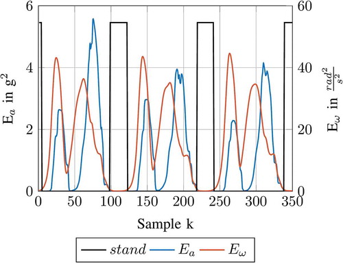
A stand phase is defined by the low signal energy of both acceleration and rotation signals, as well as known approximate values for both the absolute value of the acceleration vector (around 1 g or ) and rate of rotation in each axis (approximately
). Equation (1) and Equation (2) describe the computation of the signal energies of the acceleration and angular rate, respectively. This is done over a window of
samples around sensor sample
with the vectors of acceleration
and angular rate
, as well as the gravity constant
. A stand phase is detected if both the energy of the absolute acceleration (sans gravity) and angular rate are below their respective thresholds
and
as described by Equation (3) and visualized in .
Figure 2. Detection of stand intervals using the signal energies of acceleration and angular rate with a foot mounted sensor.
The trajectory of the foot in the swing phase describes both the step orientation and its length, thus enabling PDR. Within this phase, the current acceleration sample is rotated to the world coordinate frame using the conjugate of the current sensor orientation quaternion from the Madgwick filter. The sensor sample is then integrated as described by Equations (4) and (5) with velocity at sample
, the distance
and sample time interval
.
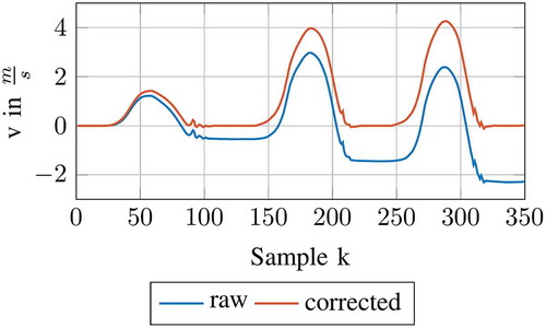
The accelerometer noise and limited resolution have a large impact on step vector estimation as the velocity error quickly accumulates. The second stand phase delimits the step trajectory and is used for a Zero-Velocity-Update (ZUPT), in which velocity offsets caused by sensor drift are measured (while standing the velocity should be zero) and henceforth corrected. We employ the ZUPT method presented by Feliz Alonso, Casanova, and Gómez-García-Bermejo (Citation2009). illustrates the resulting velocity error and correction of three swing phases and their corresponding stand phases as they are detected in . The difference in distance from start to end of one swing phase is the step vector used for indoor localization.
Figure 3. Velocity correction of three steps by ZUPT.
Both step orientation and step length are of limited accuracy, even though the velocity drift offset is compensated during the ZUPT. These inaccuracies will accumulate with each step. Regarding a pedestrian walking in a straight line, two effects are thus expected: First of all, the estimated position will increasingly drift away from the real position. Secondly, the sum of all step lengths will differ from the distance actually traveled. The major problem for this IPS lies in the aforementioned aggregation of errors. Without a correction whenever a known location is reached, for example by using infrastructure-based localization methods, the overall error has to be reduced in a different way. We propose the use of building maps to improve on the user's localization.
4. Map-based correction methods
In order to improve the described system, we propose the use of map data to correct individual steps. We use simple assumptions about human behavior to develop correction algorithms: First, we assume that pedestrians in buildings know their destination and will try to reach it via the shortest path, which reduces the number of probable paths through areas like corridors or open spaces with a limited set of entries and exits. With predefined paths provided through maps, the position estimation can better reason which step vectors are most probable and how to correct unreasonable ones. We present two correction methods based path data: Orientation Angle Correction (OAC), described in Section 4.1 and Correction using Path Information (CPI), described in Section 4.2.
Second, we assume that pedestrians cannot walk through walls and steps estimated to lead through walls are unreasonable. The errors aggregated through PDR may result in the estimated path to wrongly cross through walls instead of, for example, nearby doors. A provided building map helps the IPS to detect when walls are crossed and enables the correction of those errors. We describe the corresponding correction method Correction using Wall Information (CWI) in Section 4.3. All three correction methods are designed to be used in combination or on their own. We found the sequence of OAC first, then CPI and finally CWI to be most helpful.
To demonstrate and evaluate the following methods, we mapped a single floor of an office and lecture building with both wall and path information. Doors are interpreted as gaps in walls and indoor spaces contain the minimal number of paths to reach any door and point of interest. The maps themselves are encoded using an R*-tree.
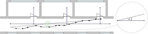
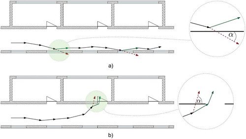
4.1. Orientation angle correction
The Orientation Angle Correction (OAC) is designed to reduce orientation errors caused by drift. In most buildings some sections exist, in which pedestrians walk in a straight line, e.g. corridors. In these sections, consecutive step vectors will be roughly parallel. If this is the case and the direction of this set of step vectors is also parallel within an angle threshold to the nearest available path, the OAC assumes that the correct orientation of the user is actually parallel to the nearest path and will henceforth correct the orientation accordingly. The principle is shown in : the pedestrian walks along the corridor but in a natural, slightly wavering path. As the angle between this path and the mapped path is smaller than the threshold, this angle will now be used to correct the orientation.
Figure 4. Calculation of Orientation Angle Correction.
The algorithm is also described in : for the sets of the last steps and the path segments closest to these steps, each set is tested whether all steps or wall segments are roughly parallel. If both sets are parallel within themselves, one element of each set is chosen and the angle between them is calculated. If the angle is smaller then a threshold, all following steps will be corrected by adding this orientation angle, even after the straight line has been left.
Figure 5. Orientation Angle Correction.
The correction algorithm only works if the correct paths within the map are found. The OAC is used in conjunction with at least one of the following methods. Without the reduction of localization error by an additional correction method, the used paths may be incorrect and thus decrease accuracy.
4.2. Correction using path information
Similar to the OAC, the Correction using Path Information (CPI) assumes that movement within a building can be abstracted to a finite number of paths. These paths can be used to correct estimated locations. describes the mechanism: It corrects the estimated position after new steps using the last estimated position and the nearest mapped path. Similar to the OAC, the algorithms check whether the step orientation is roughly parallel to the mapped path. If they are parallel, but the estimated position strays far from the path, it is corrected towards the path. ) illustrates the correction of two steps of a pedestrian walking along a corridor. The dashed red arrow depicts the steps that, while the angle towards the path is smaller than the threshold, lead further away from the path then the distance
, so that the end point of the step is corrected using the vector
. ) shows a turn that leads to no correction due to
exceeding the threshold
and a correction of the final step.
Figure 6. Correction using Path Information with as the orientation and
as the distance of a step relative to a nearby path.
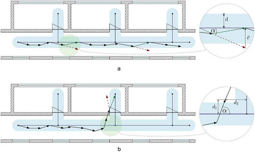
Figure 7. Correction using Path Information.
The algorithm is also described in : for each new step, the closest path to the uncorrected step is found. If the step is found to be roughly parallel to this path but is leading too far away from it (as the threshold for parallelism is quite large), the CPI will correct this step onto the path.
4.3. Correction using wall information
Another approach to improve step-based PDR systems using map data is the utilization of the fact that pedestrians cannot walk through walls. The algorithm for the Correction using Wall Information (CWI) is the most complex of the demonstrated algorithms. It consists of two mechanisms: The first is the reflection by walls, in which a perceived step crossing a wall is corrected using the assumption that the step should rather be along the wall. The position is corrected to be near, not inside the wall. The procedure is depicted in more detail in and illustrated in . The red arrows illustrate the wall crossing steps with the crossing angle . They are corrected to the green arrows as if the pedestrian was reflected from the wall. The algorithm further checks whether the corrected step would also cross a wall and recursively correct it.
Figure 8. Correction using Wall Information: Reflection by walls.
Figure 9. Correction using Wall Information with intersection angle . Acute angles lead to a search for gaps while shallow angles result in reflection.
shows this reflection mechanism in lines 2 to 22. Each step is checked whether it leads through a wall. If a wall crossing is detected, the corrected step is first set directly onto (or rather in front of) the wall. Then, the reflection is determined. If the angle of the step towards the wall is low, it is reflected off this wall at this angle (lines 13 to 17 determine the correct direction of reflection). The resulting half-step () is then also checked for wall crossings using recursion.
The second mechanism of the CWI is the use of passageways, e.g. doors. If a step vector crosses a wall with a very steep angle, the algorithm searches for a gap in the crossed wall near the crossing point (Line 23 in ). In the function , the nearest gap to both sides of the wall segment, that the step is crossing, is found recursively. If this gap would be reasonably close to the uncorrected step, a step through this gap is returned as the corrected step.
5. Determining initial position and orientation
The accuracy of navigation with PDR depends on a precise starting point and orientation. We employ a combination of GPS and PDR to determine a building entrance as the starting point of indoor positioning and use the trend of prior GPS measurements to determine the initial orientation.
When entering a building the accuracy of GPS quickly deteriorates. However, the GPS signal may not be lost well after entering the building. Instead, individual satellite signals may still be received through reflections into and throughout the building, resulting in continued and highly inaccurate positioning. It is therefore not sufficient to wait for the GPS signal to be lost to switch to PDR.
The method presented in Kim et al. (Citation2012) is well suited for determining the time of entry and is also used in this paper in a modified form. The GPS satellites with highest altitude are observed continuously. If a building is entered, the SNR of these satellites deteriorates quickly and significantly. With each step detected by our PDR method, the SNR of the three GPS satellites with the highest altitude is averaged and stored in a five-element ring buffer. With each new buffered value, the median of the stored elements is calculated and stored in another buffer. In this way, short-term fluctuations are filtered out of the signal trend. By filtering using the median of recent values, the signal trend, significant long-term changes and the precise time of the change in the data series are preserved and pronounced. A possible building entry is detected if the change of SNR in the recently filtered SNR values exceeds a threshold of 3 dB.
During the user's movement outdoors, single step vectors are stored together with the most recent GPS measurement. This way the users PDR data can be correlated with the corresponding GPS positions. If a potential building entrance has been detected by the observation of the SNR trend, the corresponding entrance of the building must be found in the map data and the entry orientation has to be determined. Without a known initial orientation the step vectors computed by PDR have an unknown error in orientation. We employ the following method to determine the initial orientation.
If the user walks at least 10 steps without a significant change in direction, the direction of the steps is approximated by a line drawn from the first to the last step of the straight PDR track. The true orientation is calculated by linear regression of the corresponding GPS measurements. If the coefficient of determination of the regression is greater than 0.85, the angle between the two lines is the angle used to calibrate the initial step orientation.
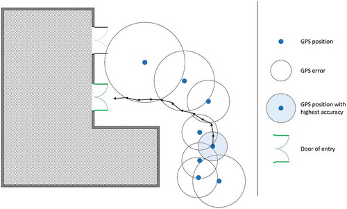
Indoor positioning starts at the user’s point of entry into the building. The following method is used to compensate for the increasing inaccuracy of GPS when approaching a building. To find the correct entry point, the most accurate of the last GPS positions is used as the temporary starting point for PDR. The last orientation-calibrated steps from this position on are chained together up until the step at the instance of entering the building. This step is determined by monitoring the change of GPS satellite SNR as described above. The door closest to this last step is used as the starting point for indoor navigation. illustrates the procedure. If no door is found within a certain search radius, the transition to indoor positioning is canceled.
Figure 10. Finding the entrance door with a precise GPS position as a temporary starting point.
6. Experiments
6.1. Map-based correction of PDR
To evaluate the proposed map-based correction algorithms, we implemented a system as described in Section 3. We then defined four routes through a non-trivial building architecture that would highlight problems with PDR localization. The routes are depicted in . All routes have a singular start and end point in order to simplify accuracy evaluations. The distance between calculated start and end points is considered the overall estimation error. Initial position and orientation are predetermined in this experiment.
Figure 11. Routes used in the experiment.
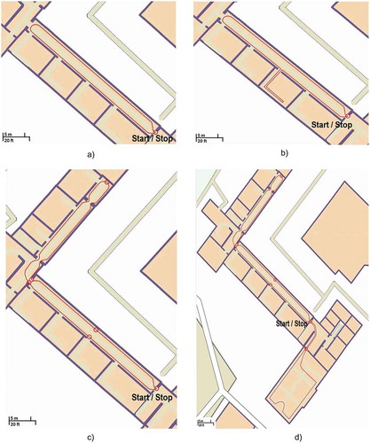
Route 1 specifically targets the drift: two long straights along the corridor will show how well the correction algorithms can keep the estimated path parallel to the corridor path. This principle is extended in Route 2: A room is entered on the return path of the corridor. Several turns and an acute-angled intersection with a door (or a wall through accumulated PDR error) may especially test the CWI algorithm. Route 3 extends Route 1 by a second corridor through a doorway and includes two 90º corners. This route will also magnify inaccurate step length estimations. An even more complex route is defined as Route 4. More corners will allow for more orientation distortion, while also provoking miscorrections.
While the localization works online, for this experiment the consecutive uncorrected step vector data from the Madgwick fusion were recorded and the path estimation was performed offline. The recordings were performed using a sensor node equipped with a Bosch Sensortec BMI160 inertial sensor and transmitting sensor signals to a connected smartphone using Bluetooth Low Energy. For the experiment, six participants each walked all four routes three times, resulting in 18 recordings per route and 72 recordings overall.
6.2. Initial orientation and position using PDR and GPS
For the evaluation of the entry detection and the initial orientation, a total of 40 test tracks were recorded using two building entrances as seen in and . For each step detected by PDR, the buffered SNR of the three satellites with the highest altitude were averaged and stored. The last GPS position was stored as well with each step vector. The user manually marks the time instance of entry using our Android App. The corresponding step vector is then marked for later evaluation. A Motorola Moto G2 is used as a GPS receiver. The phone is held in front of the user, simulating ongoing navigation using the smartphone.
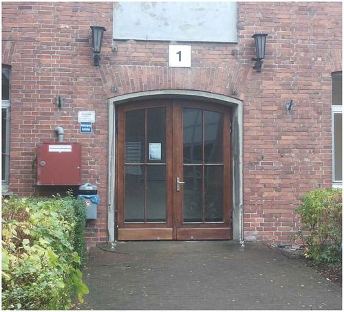
Figure 12. Entrance 1 at the northern side of the test building.
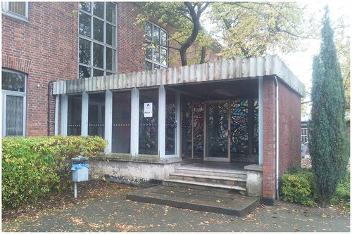
Figure 13. Entrance 2 at the southern side of the test building.
To determine the accuracy of the initial position, the distance from the end position of the marked step to the center of the entrance is measured. If the building entry is detected with a later step, the step vectors are lined up backward to the marked step.
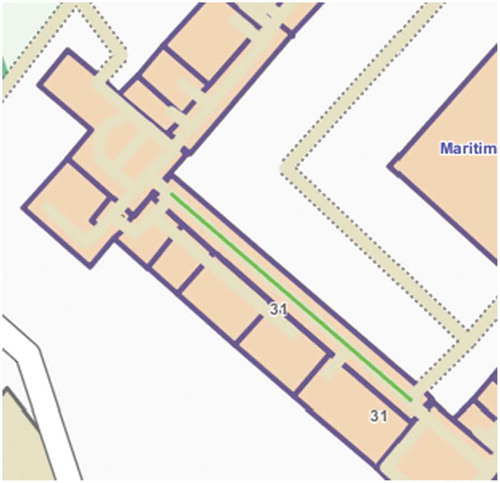
In order to evaluate the initial orientation, each track first leads into a corridor. The initial orientation is examined by comparing the orientation of the first step vectors in the corridor with a reference line along the corridor. shows the reference line in green, the two building entrances are also visible. For this experiment, the step vectors are only corrected by the calibration angle determined using GPS.
Figure 14. The position of the reference line for the initial orientation.
7. Evaluation
7.1. Accuracy of map-based correction
The first concern in IPS is the accuracy. In our experiment, we interpret the distance between the estimated end position and the actual end position (which is the same as the start position) as an accuracy metric. shows the average absolute distance between start and end point for each of the four routes and each of the four correction modes: no correction, only CPI, only CWI, and both CPI and CWI. All modes except no correction use OAC. The distances between start and end point, relative to route length, for all four correction modes are also given in .
Table 1. Accuracy results, measured as the distance between the start and end point, relative to route length. Accuracy improvements are highlighted.
Figure 15. Path estimation accuracy: Path deviation at end of each route.
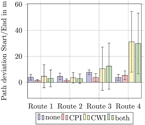
Most significant is the good performance of CPI which reduces the deviation compared to no correction by up to (Route 2). This is mostly expected since all routes travel along or parallel to relatively long straight paths at least once. However, for Route 4, CPI produces a worse result than the use of no correction. This is due to only a few recordings, where the correction leads the estimated position into the room next to the end point, where it was stuck throughout the second part of the route, resulting in a still moderately accurate estimated end position, but to a completely failed estimation for the second part of the route.
However, the performance of CWI is far below the expectations. For all routes but Route 2, the results using CWI (as well as using both algorithms) are on average worse than the PDR results without any correction. This does not constitute a systematic error but is mostly caused by a few extreme outliers in the recorded data, which is also apparent in the wide error bars in . In these outlier cases, a door or corridor is wrongly assumed to be used after an intersection with a wall. Further corrections after such an error result in a wrong path through the building or a position estimation stuck in a dead end. Especially error cases that lead to a dead end, like correction into a room instead of a corridor, may result in a large distance to the reference point of the accuracy measurement. This behavior is especially apparent in longer, more complex routes with a greater impact of accumulated localization error and consequently a greater likelihood for erroneous correction by CWI. shows such error cases for routes 3 and 4, respectively. In ) the user turns at the end of a corridor and walks back the same way. However, the corrected trajectory enters a room adjacent to the corridor in the middle of the turn, because the corresponding step intersects a wall in an acute angle. In ) the user arrives from the top right and turns left into the bottom corridor. However, the corrected trajectory leads across the corridor due to an accumulated error in length and intersects a wall in an acute angle, triggering a correction through a nearby door into the room on the bottom left. Both error cases are caused by comparatively small deviations from the actual position. The next trajectory correction by CWI employs reasonable but erroneous assumptions about the user’s intention and renders any subsequent localization unusable.
Figure 16. Erroneous dead ends by CWI halfway through routes 3 and 4. The computed user trajectory is visible as a blue line. The true paths lead back through the respective corridor.
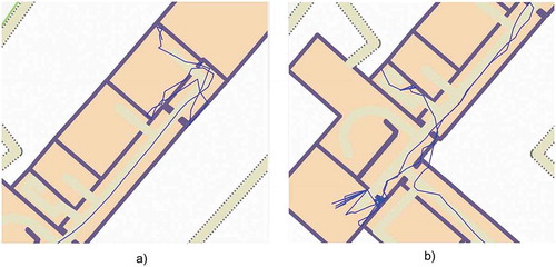
The scenarios shown in show the main source of error seen when using CWI: the decision were to guide a step after an acute intersection with a wall. CWI chooses the nearest way around a wall or through a door. However, this might not be the right decision. Especially long routes with a larger accumulated distance error may render this method unreliable. When a correction by CWI leads into a room instead of a corridor, the estimated path most likely stays in this room indefinitely, making further corrections useless. These error cases may be corrected by periodic plausibility checking of the current path and re-evaluation of past correction decisions. In case the current path is deemed implausible, past corrections may be evaluated for a plausible alternative nearby like other doors or openings into open spaces, thus resolving a dead-end error case.
7.2. Computational cost
The effect of the additional computation caused by the correction algorithms is shown in . For our experiment, we used a Motorola Moto G2 running Android 5.0.2. The graph plots the average computation time per detected step for the four correction modes: no correction, only CPI, only CWI, and both CPI and CWI. The time is averaged over all 7561 detected steps of our test data set.
Figure 17. Computation time of PDR calculation per detected step.
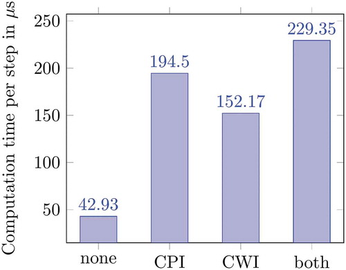
On average, the majority of computation time is used to search map data. OAC and CPI perform area searches for nearby paths. In our experiments that lead to a search for elements that intersect or lie within a 10 × 10 m bounding rectangle, likely requiring the traversal of several R*-Tree branches. CWI only performs a search for intersecting walls, searching for elements that intersect the comparatively small bounding rectangle of a step vector. This results in fewer evaluated tree branches and therefore less computational time needed for CWI. Both CPI and CWI are combined with the angle correction OAC, resulting in an offset through the comparatively costly area search by OAC.
While the correction algorithms increase computation time significantly, even on this very restricted platform computation takes far less than a millisecond for the combination of both algorithms. Thus, more than 1000 steps could be processed per second, which is clearly enough for online real-time localization.
In future work, the combination of algorithms may use some synergies, mostly the search for nearby paths could be reused, resulting in a lower computation time.
7.3. Initial orientation and position
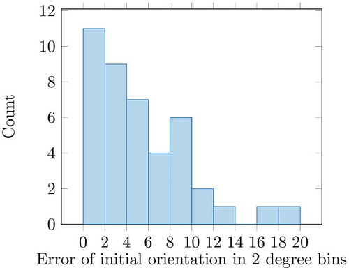
On average, the error of orientation is 4.14 degrees at entrance 1 and 6.96 degrees using entrance 2. The highest deviation is measured at entrance 2 with an error of 19.22 degrees. A possible explanation for the higher average and maximum error at entrance 2 is the vicinity of a multi-story building along the path to entrance 2. It was observed that the GPS measurements are somewhat skewed in some test runs when passing the building while actually walking straight, possibly due to multipath effects of reflected or shadowed GPS signals. This results in a GPS track that is oriented incorrectly. If this track is used for the calibration of PDR, the error is propagated to the initial orientation. shows the total distribution of initial orientation error.
Figure 18. Histogram of the initial orientation error from GPS and PDR.
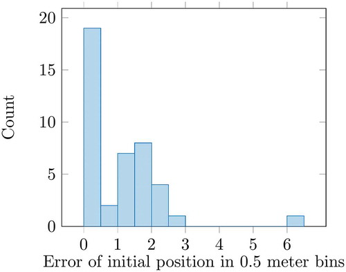
The initial position has an average error of 0.71 m using entrance 1 and 1.49 m using entrance 2. The maximum error is observed using entrance 1 with an error of 6.2 m. In this instance, the entry was not detected until the glass-enclosed entrance area was left and the stone-walled building itself was entered. In this instance, it was observed that the satellites were positioned unfavorably low and behind the user. This lead to insufficient blocking of the satellites signals by the glass front. shows the total distribution of accuracy of the initial position.
Figure 19. Histogram of the initial position error from GPS and PDR.
The experiment highlights the importance of a favorable, high altitude, GPS constellation. This limits erroneous measurements near tall buildings and allows the observation of a fast decrease of SNR when entering a building.
8. Conclusion
In this paper, we demonstrate how the use of building maps can improve PDR applications using a foot-mounted inertial sensor-based system. The benefits shown can also be applied to other step-based PDR systems, as the step vectors can be corrected regardless of the position of the sensor. We evaluated the proposed algorithms using relatively accurate step vectors measured at the pedestrians foot. Using smartwatch or smartphone internal sensors might yield less accurate step vectors. The benefit of the proposed algorithms for other sensor locations can be evaluated in future works. In addition to the shown correction methods by walls and paths, other map information like the intersection angle of paths at crossings and the length of a path are also worth investigating in the future.
The experiment showed that CWI can yield very large errors when the correction goes wrong and the position estimation becomes “trapped” inside the wrong room. We propose for future extensions of the system the use of backtracking to revert to the last plausible position and use a different step vector correction.
Furthermore, we show how the observation of GPS signals in combination with PDR is used to determine the initial position and orientation of PDR when entering a building. We also highlight challenges inherent to GPS-based calibration and entrance detection. A more sophisticated selection of GPS satellites to ensure a rapid decrease of SNR during building entry can be considered in the future. Additionally, the combination of initial positioning and orientation with continued PDR using the map-based correction methods will be examined in future works.
Additional information
Notes on contributors
Fabian Hölzke
Fabian Hölzke was born in 1990 in Berlin, Germany. He received his Bachelor of Engineering in Mechatronics and Electrical Engineering at the Esslingen University of Applied Sciences in 2014 and the Master of Science in Electrical Engineering in 2016 at the University of Rostock. In 2017 he started working as a Researcher and PhD-Student at the Institute of Applied Microelectronics and CE at the University of Rostock, where he researches indoor localization technologies based on inertial sensors.
Johann-P. Wolff
Johann-P. Wolff was born in 1988 in Rostock, Germany. He received his B.Sc. and M.Sc. in Electrical Engineering from the University of Rostock in 2011 and 2013, respectively. Since 2013 he works as a Researcher and PhD-Student at the Chair for Embedded Systems at the University of Rostock, where he researches gesture and activity recognition software for smart inertial sensor platforms and other embedded systems.
Frank Golatowski
Frank Golatowski is senior research associate and lecturer at the Institute of Applied Microelectronics and Computer Engineering, University of Rostock and head of research group on Industrial Informatics. His research focuses on embedded service-oriented architectures, Cyber-Physical Systems, Industrial Internet-of-Things, and systems engineering for safety-critical embedded systems. He is working to establish and improve interoperability and reliability as well as the real-time capability of distributed embedded systems used in different industrials domains and across domains.
Christian Haubelt
Christian Haubelt received his diploma degree in Electrical Engineering from the University of Paderborn, Germany, in 2001. He finished his Ph.D. in Computer Science and his Habilitation (postdoctoral lecture qualification) in Computer Engineering at University of Erlangen-Nuremberg, Germany, in 2005 and 2010, respectively. Since 2011, he is a Professor of Embedded Systems at the University of Rostock, Germany. His research interests include electronic system level design, system level design automation, and multi-objective optimization.
References
- Bebek, O., M. A. Suster, S. Rajgopal, M. J. Fu, X. Huang, M. C. Cavusoglu, D. J. Young, M. Mehregany, A. J. (Ton) van Den Bogert, and C. H. Mastrangelo. 2010. “Personal Navigation via Shoe Mounted Inertial Measurement Units.” Paper presented at the Intelligent Robots and Systems (IROS), 2010 IEEE/RSJ International Conference on, Taipei, China, October 18–22, pp 1052–1058.
- Bird, J., and D. Arden. 2011. “Indoor Navigation with Foot-Mounted Strapdown Inertial Navigation and Magnetic Sensors [Emerging Opportunities for Localization and Tracking].” IEEE Wireless Communications 18 (2): 28–35. doi:10.1109/MWC.2011.5751293.
- Castaneda, N., and S. Lamy-Perbal. 2010. “An Improved Shoe-Mounted Inertial Navigation System.” Paper presented at the Indoor Positioning and Indoor Navigation (IPIN), 2010 International Conference on, Zurich, Switzerland, September 15–17, pp 1–6.
- Cavallo, A., A. Cirillo, P. Cirillo, G. De Maria, P. Falco, C. Natale, and S. Pirozzi. 2014. “Experimental Comparison of Sensor Fusion Algorithms for Attitude Estimation.” IFAC Proceedings 47 (3): 7585–7591.
- Colombo, A., D. Fontanelli, D. Macii, and L. Palopoli. 2014. “Flexible Indoor Localization and Tracking Based on a Wearable Platform and Sensor Data Fusion.” IEEE Transactions on Instrumentation and Measurement 63 (4): 864–876. doi:10.1109/TIM.2013.2283546.
- Feliz Alonso, R., E. Z. Casanova, and J. Gómez-García-Bermejo. 2009. “Pedestrian Tracking Using Inertial Sensors.” Journal of Physical Agents 3 (1): 35–43.
- Foxlin, E. 2005. “Pedestrian Tracking with Shoe-Mounted Inertial Sensors.” IEEE Computer Graphics and Applications 25 (6): 38–46. doi:10.1109/MCG.2005.140.
- Gallagher, T., B. Li, A. G. Dempster, and C. Rizos. 2011. “Power Efficient Indoor/outdoor Positioning Handover.” Paper Presented at The International Conference on Indoor Positioning and Indoor Navigation (IPIN), Guimaraes, September 21–23.
- Gupta, A. K., I. Skog, and P. Händel. 2015. “Long-Term Performance Evaluation of a Foot-Mounted Pedestrian Navigation Device.” Paper presented at the India Conference (INDICON), 2015 Annual IEEE, Jamia Millia Islamia, New Delhi, India, December 17–19, pp 1–6.
- Hansen, R., R. Wind, C. S. Jensen, and B. Thomsen. 2009. “Seamless Indoor/outdoor Positioning Handover for Location-based Services in Streamspin.” Paper Presented at the 2009 Tenth International Conference on Mobile Data Management: Systems, Services and Middleware, Taipei, China, May 18–21, 267–272.
- Harle, R. 2013. “A Survey of Indoor Inertial Positioning Systems for Pedestrians.” IEEE Communications Surveys and Tutorials 15 (3): 1281–1293. doi:10.1109/SURV.2012.121912.00075.
- Huang, C., Z. Liao, and L. Zhao. 2010. “Synergism of INS and PDR in Selfcontained Pedestrian Tracking with a Miniature Sensor Module.” IEEE Sensors Journal 10 (8): 1349–1359. doi:10.1109/JSEN.2010.2044238.
- Jiménez, A. R., F. Seco, J. C. Prieto, and J. Guevara. 2010. “Indoor Pedestrian Navigation Using an INS/EKF Framework for Yaw Drift Reduction and a Foot-Mounted IMU.” Paper presented at the Positioning Navigation and Communication (WPNC), 2010 7th Workshop on, Dresden, Germany, March 11–12, pp 135–143.
- Kim, Y., S. Lee, S. Lee, and H. Cha. 2012. “A GPS Sensing Strategy for Accurate and Energy-efficient Outdoor-to-indoor Handover in Seamless Localization Systems.” Mobile Information Systems 8 (4): 315–332. doi:10.3233/MIS-2012-00151.
- Lefferts, E. J., F. L. Markley, and M. D. Shuster. 1982. “Kalman Filtering for Spacecraft Attitude Estimation.” Journal of Guidance, Control, and Dynamics 5 (5): 417–429. doi:10.2514/3.56190.
- Madgwick, S. O. H., A. J. L. Harrison, and R. Vaidyanathan. 2011. “Estimation of IMU and MARG Orientation Using a Gradient Descent Algorithm.” Paper presented at the Rehabilitation Robotics (ICORR), 2011 IEEE International Conference on, Zurich, Switzerland, June 27–July 1, pp 1–7.
- Modsching, M., R. Kramer, and K. ten Hagen. 2006. “Field Trial on GPS Accuracy in a Medium Size City: The Influence of Built-up.” Paper presented at the 3rd Workshop on Positioning, Navigation and Communication, Hannover, March 16–17, 209–218.
- Nilsson, J.-O., A. K. Gupta, and P. Händel. 2014. “Foot-Mounted Inertial Navigation Made Easy.” Paper presented at the Indoor Positioning and Indoor Navigation (IPIN), 2014 International Conference on, Busan, Korea, October 27–30, pp 24–29.
- Olivares, A., J. Ramírez, J. M. Górriz, G. Olivares, and M. Damas. 2012. “Detection of (In) Activity Periods in Human Body Motion Using Inertial Sensors: A Comparative Study.” Sensors 12 (5): 5791–5814. doi:10.3390/s120505791.
- Olsson, F., J. Rantakokko, and J. Nygårds. 2014. “Cooperative Localization Using a Foot-Mounted Inertial Navigation System and Ultrawide Band Ranging.” Paper presented at the Indoor Positioning and Indoor Navigation (IPIN), 2014 International Conference on, Busan, Korea, October 27–30, pp 122–131.
- Robertson, P., M. Angermann, and B. Krach. 2009. “Simultaneous Localization and Mapping for Pedestrians Using Only Foot-Mounted Inertial Sensors.” Paper presented at the 11th International Conference on Ubiquitous Computing, Orlando, FL, September 30–October 03, pp 93–96.
- Romanovas, M., V. Goridko, A. Al-Jawad, M. Schwaab, M. Traechtler, L. Klingbeil, and Y. Manoli. 2012. “A Study on Indoor Pedestrian Localization Algorithms with Foot-Mounted Sensors.” Paper presented at the Indoor Positioning and Indoor Navigation (IPIN), 2012 International Conference on, Sydney, Australia, November 13–15, pp 1–10. doi: 10.1094/PDIS-11-11-0999-PDN.
- Sabatini, A. M. 2006. “Quaternion-Based Extended Kalman Filter for Determining Orientation by Inertial and Magnetic Sensing.” IEEE Transactions on Biomedical Engineering 53 (7): 1346–1356. doi:10.1109/TBME.2006.875664.
- Sabatini, A. M. 2011. “Estimating Three-Dimensional Orientation of Human Body Parts by Inertial/Magnetic Sensing.” Sensors 11 (2): 1489–1525. doi:10.3390/s110201489.
- Skog, I., P. Handel, J.-O. Nilsson, and J. Rantakokko. 2010. “Zero-Velocity Detection – An Algorithm Evaluation.” IEEE Transactions on Biomedical Engineering 57 (11): 2657–2666. doi:10.1109/TBME.2010.2060723.
- Widyawan, M. K., S. Beauregard 2008. “A Backtracking Particle Filter for Fusing Building Plans with PDR Displacement Estimates.” Paper presented at the Positioning, Navigation and Communication, 2008. WPNC 2008. 5th Workshop on, Hannover, Germany, March 27, pp 207–212.
- Xiao, Z., H. Wen, A. Markham, and N. Trigoni. 2014. “Lightweight Map Matching for Indoor Localisation Using Conditional Random Fields.” Paper presented at the Proceedings of the 13th international symposium on Information processing in sensor networks, Berlin, Germany, April 15–17, pp 131–142.