
 ?Mathematical formulae have been encoded as MathML and are displayed in this HTML version using MathJax in order to improve their display. Uncheck the box to turn MathJax off. This feature requires Javascript. Click on a formula to zoom.
ABSTRACT
NaGlobal vigation Satellite System (GNSS) positioning technology is widely used for its high precision, global, and all-weather service. However, in complex environments such as urban canyons, GNSS performance is often degraded due to signal occlusion and even fails to achieve positioning due to the insufficient visible satellites. Because of the characteristics of large bandwidth, low latency, and high Base Station (BS) density, the fifth-Generation mobile communication (5G) technology has gradually become a trend for positioning in cities while offering traditional communication service. To supply the communication demands of the User Equipment (UE), only one BS is usually considered to establish a connection with the UE during the BS construction. However, the positioning accuracy with a single BS in urban canyons will be significantly reduced. To further improve the positioning accuracy in such extreme scenarios, this paper proposes a simplified 5G/GNSS fusion positioning system architecture using observations from only a 5G BS and a GNSS satellite. In this system, the GNSS receiver is mounted on the 5G BS, and the measurements provided by the receiver are used to form the differential code and complete the position estimation. The positioning mathematical models of the system based on the original code and differential code are derived. Then, the impacts of the measurements noise and the time synchronization error on the positioning accuracy are analyzed theoretically. Finally, the positioning performance is investigated by a set of simulation experiments. Numerical results show that under the existing 5G measurement noise and 2 m’s code measurement noise, the improvement of the differential code based fusion positioning compared with the 5G-only positioning is more than 32%, which is also about 6% higher than the original code based fusion positioning. Besides, this improvement is not affected by the time synchronization error between the BS and the GNSS satellite.
1. Introduction
The development of Global vigation Satellite System (GNSS) improves the accuracy and reliability of outdoor positioning. However, since the satellite signals cannot pass through obstacles, and the interference of multipath signals to Line Of Sight (LOS) signals, the positioning performance of GNSS in urban canyons is significantly reduced, and it even cannot achieve effective positioning (Seco-NaGranados et al. Citation2012). To improve the effectiveness and accuracy of urban environment positioning, the multi-sensor fusion-based positioning, such as the integration of GNSS, inertial vigation system, vision, and other technologies, has become the main choice (Xie etna al. Citation2014; Aumayer, Petovello, and Lachapelle Citation2014). Unfortunately, the power consumption, size, and cost of multiple sensors restrict its applications, especially for the pedestrian users. With the popularity of smartphones and the continuous improvement of communication bandwidth, the utilization of the fifth-Generation mobile communication (5G) signal for positioning has become a rising research focus (Keating et al. Citation2019).
To satisfy different positioning requirements, the 5G radio access network provides rich local positioning technologies, including signal feature matching positioning, distance intersection positioning, angle intersection positioning, Enhanced Cell-ID (E-CID) positioning, etc. (Lin and Lee Citation2021). The signal feature matching positioning requires to establish the fingerprint information database of signal strength (Tomofumi et al. Citation2019), and this process is complex and the positioning accuracy is limited. Hiltunen et al. (Citation2015) achieved a positioning accuracy of 62 m in Long-Term Evolution (LTE) cellular by using signal feature matching. Therefore, it is not suitable for high-precision positioning and will not be discussed in this paper.
The distance intersection positioning is one of the most commonly used methods in 5 G positioning (Del Peral-Rosado et al. Citation2018). Based on the Time Of Arrival (TOA) of radio signals obtained from 5 G positioning reference signals, the distance measurement from the Base Station (BS) to the User Equipment (UE) is generated. The accuracy of TOA measurements is affected by the signal frequency, the number of subcarriers, the time synchronization error between BS and UE, the Non-Line Of Sight (NLOS) and multipath error, etc. In the static test scenarios, Liu et al. (Citation2022) achieved a TOA ranging accuracy of 0.5 m using a commercial LTE base station and cell reference signals. Ferre, Seco-Granados, and Lohan (Citation2019) analyzed the positioning accuracy of 5 G signals with different frequencies and subcarrier number, and found that the positioning accuracy with sub-6 GHz was between 1–6 m, and that of millimeter-wave above 24 GHz was within 1 m. They also pointed out that the time synchronization error between BS and UE had a great influence on the TOA measurements, and a time synchronization error of 1 μs would lead to a distance error of 300 m. Koivisto et al. (Citation2017) found that the positioning accuracy of BS and UE was far worse when no time synchronization was achieved. For this reason, in the 5G system the Round-Trip-Time (RTT) and Time Difference Of Arrival (TDOA) measurements are constructed, together with the corresponding positioning methods (TSG RAN (Technical Specification Group Radio Access Network) Citation2019, Citation2020). The former requires a two-way ranging between BS and UE, and the latter belongs to a hyperbolic positioning affected by the time synchronization error between the BSs (Gentner, Sand, and Dammann Citation2012). At present, the time synchronization between BSs is mainly realized by the GNSS receivers mounted on BSs and the time synchronization protocol, and the time synchronization accuracy can be kept within 3 ns (Xiong and Wang Citation2022).
The angle intersection positioning relies on massive Multi-Input Multi-Output (MIMO) and beams forming technology of 5G BSs, and the UpLink Angles Of Arrival (UL-AOA) or DownLink Angles Of Departure (DL-AOD) are used in the positioning. The angle measurement is not affected by the time synchronization error between BS and UE (Sun et al. Citation2020), but by the antenna array element number, the signal-to-noise ratios, the antenna orientation calibration error, the distance between BS and UE, the NLOS and multipath error, etc. (TSG RAN (Technical Specification Group Radio Access Network) Citation2021; Shahmansoori et al. Citation2018).
In terms of the above two intersection positioning, at least 2 BSs are required for angle intersection and 3 BSs for distance intersection under the premise of time synchronization. However, as the 5G BSs are mainly designed for communication applications and set up in urban environments, the number of available BSs can hardly satisfy the requirements of positioning. In addition, the poor geometry of the adopted BSs also has a negative impact on the positioning accuracy (Guo et al. Citation2020).
The E-CID positioning integrates the RTT and the angle measurements to complete positioning with a single BS (Del Peral-Rosado et al. Citation2020). Compared with the distance or angle intersection positioning, the E-CID positioning is not affected by the time synchronization errors between BSs and between BS and UE, and is not affected by the geometric distribution of BSs neither. However, since there is no redundant measurement in E-CID positioning, the reliability of the positioning result is greatly reduced. Shahmansoori et al. (Citation2018) studied the accuracy of E-CID positioning in the presence of scattering points, and found that the angle measurement was greatly affected by the multipath and NLOS errors, and the positioning accuracy would be seriously decreased if those errors were not corrected.
In urban canyon and other complex scenarios, both 5G positioning and GNSS positioning are facing with the problems of fewer available signals and decreased measurement accuracy (Garcia et al. Citation2017). Therefore, in many contributions the 5G/GNSS fusion positioning technique was proposed to improve the positioning accuracy and reliability compared with single positioning system (Abu-Shaban et al. Citation2018; Del Peral-Rosado et al. Citation2018). Del Peral-Rosado et al. (Citation2018) found that the additional 5G BS improved the geometric distribution of the vigation satellites and thus effectively improved the positioning accuracy in urban canyons. Destino etna al. (Citation2018) used the 5G TOA and AOA measurements and the GNSS codes for fusion positioning, and deduced the positioning errors of satellite signals and 5G signals with different signal-to-noise ratios and carrier-to-noise ratios. Del Peral-Rosado et al. (Citation2019) used multipath, NLOS errors satellite visibility and other factors in the modeling and simulation of measurements, and analyzed their influence on 5G/GNSS positioning. They found that the 5G/GNSS fusion positioning ensures a horizontal accuracy below 5 m on the 95% of cases. As the 5G stations are mainly sited for the purpose of mobile communication, Zhang, Li, and Chen (Citation2021) pointed out that in nearly 30% of cellular networks, phones can receive 5G signals from only one BS. Besides, the number of satellites tracked inside dense buildings is also limited, especially for a single GNSS system. Del Peral-Rosado et al. (Citation2018) analyzed the satellite visibility of four main GNSS constellations using a 3D urban map of 3.24 square kilometers and found that the satellites visibility of a single constellation was very poor in dense urban areas. In the case of GPS, the number of LOS satellites was less than 3, or even only 1.
To solve the positioning problem in complex scenarios such as urban canyons, this paper proposes a fusion positioning system using a single 5G/GNSS BS and tracking a single GNSS satellite, which is a basis of the fusion positioning system with multiple BSs and multiple GNSS satellites. This system is timed via the GNSS receiver mounted on the 5 G BS. Based on the E-CID positioning, the tightly combined 5 G/GNSS positioning is achieved by constructing differential satellite codes, as well as 5 G RTT and AOD measurements. This method can effectively improve the positioning accuracy without increase of the BS number, and remove the accuracy requirement of time synchronization between the BS and the satellite.
The rest of this paper is organized as follows: In “5G/GNSS Fusion Positioning Model”, the SFS and the corresponding positioning algorithm are introduced, where the original codes are utilized. In “5G/GNSS fusion positioning with differential code”, the improved 5 G/GNSS fusion positioning algorithm with differential codes is derived in the SFS. In “Analysis of positioning errors”, some factors affecting the 5G/GNSS fusion positioning errors are discussed. In “Simulation experiments and results analysis”, simulated experiments are used to further analyze the impact of these factors on the positioning errors, and the performance of the final positioning results are discussed as well. Finally, some conclusions are given.
2. 5G/GNSS fusion positioning model
There are three kinds of measurements in 5G positioning: the signal strength, the signal propagation time, and the DL-AOD or UL-AOA. Since the signal strength is greatly affected by the signal propagation environment and has low ranging accuracy, only the signal propagation time and angle are used herein. The signal propagation time is the transmission time of a 5G signal between the BS and the UE. In theory, its product with the speed of light is the distance between BS and UE. However, the measured distance between the BS and the UE will be contaminated by the multipath, the NLOS transmission, the device hardware delay, etc. For the TOA measurements, the time synchronization error between 5G BS and UE is also included. However, this error does not affect the RTT measurements, which is composed of both uplink and downlink measurements. The RTT measurement is expressed as follows:
where and
are the epochs when the BS sends and receives a range signal, and
,
are the epochs when the UE receives and sends a range signal.
is the residual including the hardware delay errors within UE and BS and the NLOS transmission error or multipath. Therefore, the observation equation of the 5G RTT measurement
can be expressed as:
where is the speed of light,
is the coordinate vector of the UE in the east, north, and up directions with respect to the 5G MIMO antenna.
The angle measurement is a departure or arrival angle of the signal measured by the antenna array of BS. Take the DL-AOD as an example, and its azimuth angle and elevation angle
can be expressed as:
where and
are the residual errors of azimuth angle and elevation angle respectively. Herein, we call this coordinate system the 5G antenna system. Therefore, from observation EquationEquations (2)
(2)
(2) and (Equation3
(3)
(3) ), we can get the E-CID positioning result as expressed
However, the above positioning result is not reliable because there is no redundant measurement and the used measurements contain some errors.
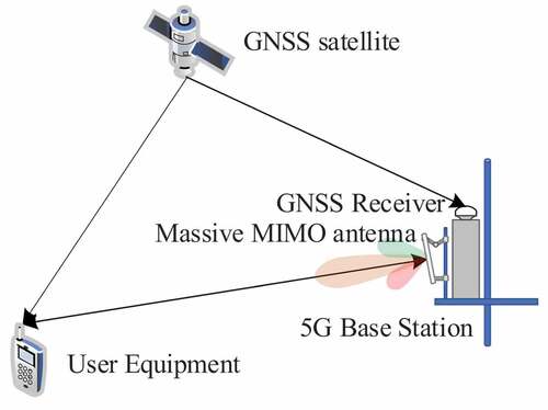
When the satellite measurement is added, the fusion positioning will improve the accuracy and reliability of the positioning results. Therefore, aiming at the positioning requirements under extreme conditions, we make full use of the information provided by the BS and the GNSS receiver mounted on the BS, and establish a 5G/GNSS fusion positioning system with only a single BS and a single satellite, which is med as the Simplified Fusion System (SFS) in this paper. Since we believe that in the UE terminal the 5G antenna and the GNSS antenna are integrated in ana device, the GNSS receiver is only called for the BS hereinafter. The structure of the utilized SFS is shown in .
Figure 1. Structure of the SFS.
In the Earth-Centered, Earth Fixed (ECEF) coordinate system, the code received from a satellite for the UE can be expressed as:
where is the distance between the satellite and the UE,
is the synchronization error between the GNSS satellite and the UE in unit of time,
and
are ionospheric and tropospheric delays, and
is the unmodeled residual.
Assuming the geodetic coordinate the 5G antenna is known (from this we can obtain the ECEF coordinate
of the 5G antenna), the relationship between the coordinate of the UE in the 5G antenna system
and that in the ECEF system
can be expressed as:
where is the transformation matrix between the above two coordinate systems. Then the coordinate in the ECEF system can be rewritten by the coordinate in the 5G antenna system as
where is the inverse matrix of
. Therefore, the coordinate increment of the UE in the ECEF system
after the first-order Taylor series expansion of measurements can be expressed by that in the 5G antenna system
as:
From EquationEquation (4)(4)
(4) of the 5G-only positioning we can obtain an approximate coordinate
for the UE from the range and angle measurements, then through EquationEquation (7)
(7)
(7) we can obtain the counterpart
in the ECEF coordinate system. Combining EquationEquations (5)
(5)
(5) and (Equation8
(8)
(8) ), we can obtain the linearized code observation equation. Then together with EquationEquations (2)
(2)
(2) and (Equation3
(3)
(3) ), we can get the final observation equation of the 5G/GNSS fusion system at the approximate point
, which can be expressed as follows:
where the subscript 0 denotes the initial value for an approximate position of the UE. and
are the design matrices of the original code and 5G measurements expressed as:
where is the unit vector along the LOS,
is the position of the satellite, and
is the projection length of the approximate distance between BS and UE on the horizontal plane.
As for the stochastic model, considering different kinds of observations are independent for each other, thus the weight matrix of the observations can be formed as a diagonal matrix expressed as
where ,
,
and
are the noises of the original code, RTT, azimuth and elevation measurements. In practical, the above noises are set as 0.3 m, 1 m, 2 °, and 2 ° respectively (Su, Zhang, and Lu Citation2021; Peng et al. Citation2020).
When using an iterative weighted least squares adjustment, the estimated coordinate in the 5G antenna system for the UE and the synchronization error between the satellite and the UE can be obtained as
where ,
. In general, to ensure the stability of the estimator,
will be replaced by
in the experiment in EquationEquation (11)
(11)
(11) . Where
is a very small number. The covariance matrix of the estimator is:
where is the scaling factor, which is depended on measurements residues.
In general, the condition number of will vary with the initial coordinate of UE and the accuracy of the observations in. The three-dimensional position estimation accuracy can be expressed as the trace of the covariance matrix:
From the observation equation of SFS with the original code in EquationEquation (5)(5)
(5) , we can find that the additional code measurement also brings an unknown parameter
. Therefore, its degree of freedom is still identical to that in the E-CID positioning, and the model isn’t strengthened. Although
can be ignored when precise time synchronization is achieved between UE and GNSS satellite, however, this is usually hard to realize.
3. 5G/GNSS fusion positioning with differential code
To alleviate the requirements of 5G/GNSS fusion positioning on time synchronization accuracy in the above algorithm with the original code, we use the code generated from the GNSS receiver mounted on the BS to construct the differential code and realize the time synchronization between the BS and the UE through 5G communication. The time datum in the BS of our SFS is assumed to be provided by the GNSS receiver, thus the time in the MIMO antenna and that in the GNSS receiver can be regarded completely synchronized. Furthermore, in the 5G/GNSS fusion positioning with the differential code, the positions of the 5G MIMO antenna and the GNSS receiver are known in advance, while the position of the UE is to be determined.
For the GNSS receiver mounted on the BS, its code measurement is
where is the geometric distance from the satellite to the GNSS receiver, which can be easily calculated with the broadcast ephemeris,
is the synchronization error between the BS and satellite. By differencing the original code in the UE with EquationEquation (5)
(5)
(5) and that in the GNSS receiver with EquationEquation (16)
(16)
(16) from a common satellite s, the atmospheric delays can almost be removed since the distance between the BS and the UE is usually very close, and the differential code can be obtained as
The difference of the time synchronization errors between and
can be transferred to the time synchronization error between the BS and the UE, i.e.
, which is written as
The error can be limited within a small range through 5G communication in the SFS, thus it is usually ignored in the study of 3GPP (2019). For this reason, the observation equation of the differential code in EquationEquation (17)
(17)
(17) can be simplified to
Compared with the original code in EquationEquation (5)(5)
(5) , the differential code in EquationEquation (19)
(19)
(19) is more accurate. At this time, the original code is replaced by the differential code, and EquationEquation (9)
(9)
(9) becomes
Accordingly, the first term in the weight matrix of EquationEquation (12)(12)
(12) is changed to
, and
m by the law of the error propagation. When using iterative weighted least squares, the same formulas from EquationEquation (13)
(13)
(13) to EquationEquation (15)
(15)
(15) are applied. The procedures of the 5G/GNSS fusion positioning for the original code and the differential code are generally the same, which can be depicted in . The only difference between these two algorithms is the forms of
and
for the differential code are changed to
Figure 2. The process flow chart of 5G/GNSS fusion positioning.
4. Analysis of positioning errors
From EquationEquations (19)(19)
(19) and (Equation20
(20)
(20) ), we can see that the GNSS receiver mounted on the BS only helps form the differential code and remove the synchronization error and the atmospheric delays. Since the location of the GNSS receiver is known in advance,
can also be easily calculated, and the relevant term in the vector
and the subsequent positioning result are in fact free from the specific location of the GNSS receiver. As a result, the GNSS receiver can be set up anywhere around the UE as long as the time synchronization between the 5G antenna and the GNSS receiver can be guaranteed. In general, the longest distance between the GNSS receiver and UE is only a few kilometers.
From the proof in the Appendix, we can conclude that the accuracy in 5G/GNSS fusion positioning is smaller than that in the 5G-only positioning
. In fact, the derivation also implies that the positioning accuracy can be further improved as long as the number of observations increases, no matter which kind of observation is added. This also confirms that the SFS is the basic form of the fusion system with 5G signals and GNSS signals.
4.1 Measurement noise
It can be seen from EquationEquation (36)(36)
(36) that the positioning accuracy of the fusion positioning algorithm is positively correlated with the noise of code. In general, the theoretical noise of the original code is 1% of its code chips length, which is about 0.3 m (Su, Zhang, and Lu Citation2021). The noise of differential code can be obtained from the noise of original code and the law of error propagation. If the code in the UE and in the GNSS receiver are not corrected, the positioning accuracy will be reduced. Besides the time synchronization error, the ionospheric delay and tropospheric delay are also main factors in GNSS positioning with original code. Even if the empirical models are used, the residual of the ionospheric delay after correction is in the order of several meters to tens of meters, and that of the tropospheric delay is up to several meters (Wu et al. Citation2008; Martellucci and Cerdeira Citation2009). Comparatively, the atmospheric delays can be ignored for the differential code.
As for the 5G measurements, the coefficient matrix of the linearized equation derived from EquationEquation (4)(4)
(4) is
Then according to the law of error propagation, the prior position accuracy of the 5G-only positioning can be expressed as
According to EquationEquation (23)(23)
(23) , the accuracy of 5G positioning depends on three factors including the noises of 5G measurements, the distance and elevation between the BS and the UE. Specifically, it is positively correlated with the first two factors and negatively correlated with the absolute value of the last factor. It should be noted that in the Appendix we can also obtain the position accuracy of the 5G-only positioning, expressed as
. However, this is a posterior position accuracy after estimation.
4.2 Time synchronization
In the 3GPP protocol, the timing error of the BS and the UE is modeled as following the zero-mean-truncated Gaussian distribution (TSG RAN (Technical Specification Group Radio Access Network) Citation2021), so the range of and
can be expressed as:
where and
are the timing accuracy of the BS and the UE respectively. Therefore, the observation errors of code and RTT can be expressed as:
where ,
and
are the noises of the RTT and codes generated by the UE and GNSS receiver respectively.
,
, and
are the unmodeled errors including the residual of the atmospheric delay after correction, multipath effect, etc. It can be seen that the difference process increases the noise level of the observations, but reduces the residual error related to the satellite. If original codes are used and broadcast ephemeris is used to correct other sources of error, the noise level of the observations is lower, but the residual error is larger than that of the differential codes. In general, the magnitude of the residual error is greater than the noise by the original code, so it is better to use differential codes. In the actual environment, it is the possible contribution of using a GNSS signal with a lower noise level, e.g. the Galileo E5 signal. Obviously, the observation error is positively correlated with the accuracy of the relevant errors. Therefore, the relationship between time synchronization accuracy and positioning accuracy is also positively correlated.
5. Simulation experiments and results analysis
To analyze the positioning performance of the SFS, we conduct a simulated experiment where the ECEF coordinates of the UE adopt the results of real-time kinematic positioning from collected baseline data with 1366 epochs, and the position of the BS in the simulated experiments use the real location of the BS in the baseline. Then the range and angle in the 5G measurements and the GNSS codes are generated accordingly.
5.1 Simulation data generation
The 5G measurements were generated by NYUSIM, an open-source 5G channel simulator developed by Rappaport et al. (Citation2013), in combination with the relevant information of the baseline data. The generation procedure of the simulated measurements is shown in .
Figure 3. The procedure of the measurements’ generation.
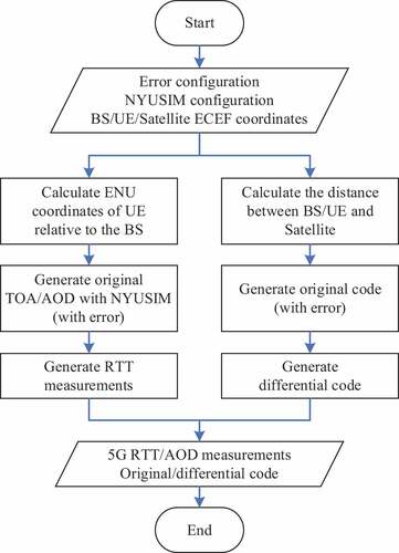
In Section “Analysis of positioning errors”, we point out that the fusion positioning result is free from the specific location of the GNSS receiver, so we assume the phase center position of the GNSS antenna and that of the massive MIMO antenna are the same for convenience, and this coordinate is taken as the BS coordinate in the simulation experiment. As can be seen from , the ECEF coordinates of the BS, the UE, and the satellite, measurements error configuration, and NYUSIM configuration are known. Where the ECEF coordinates of the satellite can be obtained by the precise ephemeris. In the generation of 5G measurements, we first calculate the coordinates of UE in the 5G antenna system, then put these coordinates into the NYUSIM software to generate the original TOA and AOD measurements, and finally calculate the RTT measurements according to TOA. For the generation of codes, the distances between the stations and the satellite are calculated at every epoch, and then the original and differential codes are calculated considering all kinds of errors. It should be noted that only single GNSS system is included in this simulation process, not limited to GPS, GLONASS, Galileo or BDS.
Considering the observation errors in extreme positioning scenarios such as urban canyons (Ferre, Seco-Granados, and Lohan Citation2019; Shahmansoori et al. Citation2018; Wanninger and Heßelbarth Citation2020; Peng et al. Citation2020), we set ,
,
, and
to be 2.0 m, 0.3 m, 2.0 m, and 0.0 m,
to be 1.0 m,
and
to be 2.0 °, and
and
to be 5.0 ns and 1.0 ns, respectively.
3GPP R17 guides to use the indicators that positioning error percentages of 50%, 67%, 80%, and 90% to evaluate the performance of 5G positioning technology (TSG RAN (Technical Specification Group Radio Access Network) Citation2021), thus this paper evaluates the positioning performance with a 90% positioning error. Positioning error is calculated by comparing the known position and the estimation results. The analysis results of the positioning error in the previous section will be verified and the overall positioning performance will also be evaluated. All results in 5 G-only E-CID positioning and 5 G/GNSS fusion positioning with either the original code or the differential code will be discussed, which will be marked as “5G”, “OCF”, and “DCF” respectively.
5.2 Impact of measurement noise on positioning results
Due to the difference of GNSS chips and antennas equipped by different terminals, the actual code noise varies from one to another. Considering the influence of positioning scenarios and hardware conditions, the code noise received by the UE is assumed to be 0.50 m, 2.00 m, and 5.00 m respectively. Except the variable noise of codes, the configuration information of other errors keeps the same as that in Chapter 5.1. The corresponding positioning accuracies and the improvements to the 5G-only positioning are shown in .
Table 1. Positioning results of different positioning models with different code noises.
As can be seen in , the change of code noise has a significant impact on the result of fusion positioning. With the increase of code noise, the improvement of fusion positioning is gradually weakened compared with the 5G positioning. Although the performance of fusion positioning with the differential code is slightly better than that with the original code, its superiority also decreases with the increase of code noise. When is 0.50 m, the improvement of the fusion positioning compared with 5 G positioning is more than 20%, and that with the differential code is 10% higher than that with the original code. However, when
increases to 5.00 m, the improvement of the fusion positioning becomes less than 15%, and the values of two fusion models become almost the same. The smaller accuracy improvement of the differential code compared with the original code under larger code noise is caused by the decreased advantage of the atmospheric delay mitigation and time synchronization between the BS and the satellite, when the code noise becomes the dominant factor that affect the positioning results.
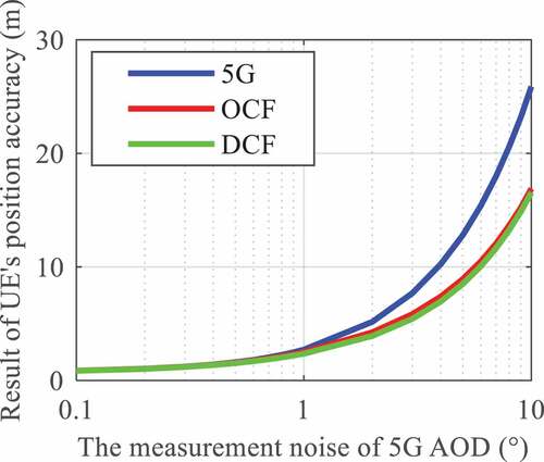
Considering the estimation accuracy of massive MIMO antenna direction of arrival and the influence in extreme environments (Del Peral-Rosado et al. Citation2019), the noise of 5G AOD traverses from 0.1° to 10° with different intervals, while other configuration values are consistent with those in Chapter 5.1. The positioning results are shown in . From the figure we can see that when the AOD noise ranges from 0.1° to 1°, the positioning performance of the fusion positioning is very close to that of the 5G positioning. However, when the AOD noise varies from 1° to 10°, the improvement effect of the fusion positioning on 5G positioning is gradually enhanced. This is because the positioning result is mainly affected by other factors when the AOD noise is smaller than 1°, while the AOD noise gradually becomes the main factor when it is greater than 1°. Besides, the figure also shows that the accuracy of fusion positioning with the differential code and that with the original code are almost undistinguished. This indicates that the 5G AOD noise has few impacts on the performance difference of fusion positioning between the original code and the differential code.
Figure 4. Impact of measurement noise of 5G AOD on UE’s positioning accuracy.
If the effect of synchronization error is ignored, from EquationEquation (25)(25)
(25) the RTT observation error is mainly determined by its noise
. Based on the configuration information in Chapter 5.1, the noise of RTT measurements was set to explore its influence on positioning results, as shown in . The results show almost unchanged positioning accuracy for both the 5 G-only positioning and the fusion positioning when the RTT measurement noise is within the range between 0.1 m and 1 m.
Figure 5. Impact of measurement noise of 5G RTT on positioning accuracy.
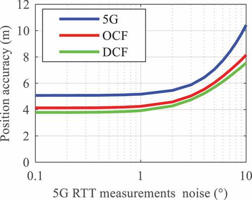
When the RTT noise is larger than 1 m, the positioning accuracies in all three models gradually get larger, but the performance differences among these three models are hardly changed until the RTT noise reaches close to 10 m, when the increase of the 5 G positioning accuracy is faster than the fusion positioning. Besides, with any magnitude of RTT noise from 0.1 m to 10 m, the differential code based fusion positioning achieves the best positioning performance, the original code based fusion positioning achieves slightly worse positioning results, and the 5 G-only positioning achieves the worst accuracy. This indicates the RTT noise has almost the same impact on the three positioning models. It can be explained by EquationEquation (23)(23)
(23) and “Appendix”.
5.3 Impact of time synchronization accuracy on positioning results
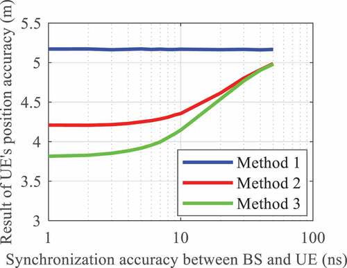
As introduced on 5 G positioning in 3GPP R17 standards, the standard deviation of timing error of BS and UE is usually within 0–50 ns (TSG RAN (Technical Specification Group Radio Access Network) Citation2021). Herein, the time synchronization accuracy between the BS and the UE is simulated from 1 ns to 50 ns, and other information kept unchanged. In this way, the positioning results in the three models are achieved and displayed in . Obviously, the accuracy of the 5 G-only positioning is free from the time synchronization accuracy between the BS and the UE, but it is still the worst compared with other two models in the fusion positioning. On the other hand, the accuracy of the fusion positioning will gradually decrease as this time synchronization error increases, and the improvement of the differential code based fusion positioning to that of the original code based fusion positioning will gradually decrease as well. When is 1 ns, the positioning accuracy with the differential code is 0.4 m higher than that with the original code. However, when
increases close to 50 ns, the positioning performances of these two models become almost the same.
Figure 6. Impact of time synchronization accuracy between the BS and the UE on positioning accuracy.
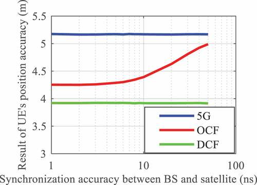
The timing error between the BS and the satellite has the same range of standard deviation as that between the BS and the UE, i.e. also within 0–50 ns. Therefore, we set the time synchronization error between the BS and the satellite from 1 ns to 50 ns again. The positioning accuracies under different synchronization errors in the three models are obtained and displayed in . The results show that apart from the fusion positioning with the original code, both the positioning accuracies in other two models are free from the time synchronization error between the BS and the satellite. This is because this time synchronization error is eliminated in the differential code. Therefore, the performance of the differential code based fusion positioning is always better than that of the original code based fusion positioning, and their difference will gradually get larger as the increase of the synchronization error from 4 ns.
Figure 7. Impact of time synchronization accuracy between the BS and the satellite on positioning accuracy.
5.4 Performance analysis of the positioning results
After the impact of measurement noise and time synchronization error on positioning accuracies in different models are discussed, in this subsection we will further analyze the overall performance of different positioning models based on the configuration information in Chapter 5.1. The simulated data are processed in an epoch-by-epoch mode, and the positioning biases in the east (E), north (N), and up (U) directions using the 5G based E-CID algorithm, the original code based fusion positioning algorithm, and the differential code based fusion positioning algorithm are depicted in .
Figure 8. The positioning results of different positioning algorithms.
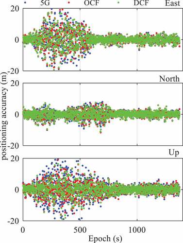
From we can see that there are large biases of positioning results in the E and U directions from about the 200th epoch to the 600th epoch. This is caused by the large distance between the BS and the UE. In addition, the fluctuation range of the differential code based fusion positioning is smaller than that of 5G positioning and original code based fusion positioning. In general, all the positioning results obey a typical standard normal distribution. Therefore, we calculate the positioning accuracy of the three algorithms in the E, N, and U directions with an error percentage of 90% and their improvements to the 5G-only positioning, as listed in .
Table 2. Positioning results of three algorithms in the east, north, and up directions.
As can be seen from , the fusion positioning has an obvious improvement compared with the 5 G positioning, especially in the U direction. In the E and N directions, the improvement of fusion positioning over the 5 G positioning is more than 6% with the original code and around 10% with the differential code. In the U direction, this value is up to 26% and 32%, respectively. Therefore, the performance of the differential code based fusion positioning is slightly better than that of the original code-based fusion positioning.
6. Conclusions
Aiming at the 5 G/GNSS fusion positioning in extreme scenarios such as urban canyons, this paper proposed a simplified 5 G/GNSS fusion positioning system architecture using observations from only a 5 G BS and a GNSS satellite. This system can be a basis of the fusion positioning system with multiple BSs and multiple satellites. Based on the 5 G E-CID positioning, the system extends the measurements provided by the GNSS receiver mounted on the 5 G BS and derives the 5 G/GNSS fusion positioning model together with the 5 G RTT and AOD measurements. The original code on the UE side and the differential code between the BS side and the UE side are utilized separately for two different fusion positioning models. On this basis, the factors that affect the positioning performance are discussed theoretically and analyzed in a set of simulation experiments, together with a demonstration and comparation of the positioning accuracy for the 5 G-only positioning and two different 5 G/GNSS fusion positioning.
The theoretical analysis shows that the accuracy of fusion positioning is affected by the measurement noise and the time synchronization error, and the differential code can reduce the influence of the atmospheric delay residuals and thus improve the accuracy of the observations. Simulated experiment results show that compared with the 5 G-only positioning, the 5 G/GNSS fusion positioning has better positioning performance, and can alleviate the impact of the 5 G measurement noise. Besides, compared with the original code based fusion positioning, the differential code based fusion positioning has higher positioning accuracy and has no requirement of the time synchronization between the BS and the GNSS satellite. With noises of 2° for the AOD, 1 m for the RTT, and 2 m for the original code, the improvement of the differential code based fusion positioning to the 5 G positioning is more than 32%, which is 6% higher than the original code based fusion positioning.
We should realize that although the SFS, the 5 G/GNSS fusion positioning models with the original code or differential code, and their positioning performance have been preliminarily investigated in this paper, some factors that may also affect the positioning performance, such as the observation type, the geometric distribution of the data sources, and other systematic errors, are not discussed. Experiments with real data are also our next research direction. Therefore, more comprehensive research should be carried out in the future to further exploit the approach to improve the positioning results.
Disclosure statement
No potential conflict of interest was reported by the author(s).
Data availability statement
The data that support the findings of this study are available from the corresponding author, upon reasonable request.
Correction Statement
This article has been corrected with minor changes. These changes do not impact the academic content of the article.
Additional information
Funding
Notes on contributors
Chi Guo
Chi Guo received the Ph.D. degree in computer science from Wuhan University, Hubei province, China. Currently, he is a professor at GNSS Research Center of Wuhan University. His current research interests include BeiDou application, unmanned system navigation, and Location Based Services (LBS).
Shufeng Qi
Shufeng Qi received the B.S. degree in Faculty of Geosciences and Environmental Engineering, Southwest Jiaotong University, in 2020. He is currently pursuing the M.S. degree in GNSS Research Center, Wuhan University, China. His area of interests includes 5G positioning and 5G/GNSS.
Wenfei Guo
Wenfei Guo is an associate professor at GNSS Research Center, Wuhan University. He received his Ph.D. degree in Communication and Information Systems from Wuhan University in 2011. His research focuses on GNSS receivers and relevant signal-processing technologies, including high precise timing receivers, GNSS-R receivers, and anti-jamming receivers.
Chenlong Deng
Chenlong Deng received his Ph.D. degree from Wuhan University, China, in 2016, and is currently a research fellow at GNSS Research Center of Wuhan University. His current research interests include multi-frequency and multi-system ambiguity resolution and model analysis in precise positioning.
Jingnan Liu
Jingnan Liu is the Academician of Chinese Academy of Engineering, and the professor at the GNSS Research Center, Wuhan University, China. His research focuses on satellite geodetic theories, methods, and data processing, satellite navigation methods, data processing, and applications.
References
- Abu-Shaban, Z., X. Zhou, T. Abhayapala, G. Seco-Granados, and H. Wymeersch. 2018. “Error Bounds for Uplink and Downlink 3D Localization in 5G Millimeter Wave Systems.” IEEE Transactions on Wireless Communications 17 (8): 4939–4954. doi:10.1109/TWC.2018.2832134.
- Aumayer, B. M., M. G. Petovello, and G. Lachapelle. 2014. “Development of a Tightly Coupled Vision/GNSS System”. In 27th International Technical Meeting of The Satellite Division of the Institute of Navigation, 2202–2201, Tampa, September 8–12.
- Cong, L., A. I. Abidat, and Z. Tan. 2006. “Analysis and Simulation of the GDOP of Satellite Navigation.” Acta Electronica Sinica 34 (12): 2204–2208.
- Del Peral-Rosado, J. A., O. Renaudin, C. Gentner, R. Raulefs, E. Dom´ınguez-Tijero, A. Fernández-Cabezas, F. Fernando Blázquez-Luengo, et al. 2019. “Physical-Layer Abstraction for Hybrid GNSS and 5G Positioning Evaluations”. In IEEE 90th Vehicular Technology Conference (VTC2019-Fall), 1–6, Honolulu, September 22–25. doi:10.1109/VTCFall.2019.8891529.
- Del Peral-Rosado, J. A., F. Gunnarsson, S. Dwivedi, S. M. Razavi, O. Renaudin, J. A. López-Salcedo, and G. Seco-Granados. 2020. “Exploitation of 3D City Maps for Hybrid 5G RTT and GNSS Positioning Simulations”. In IEEE International Conference on Acoustics, Speech and Signal Processing (ICASSP), 9205–9209, Barcelona, May 4–8. doi:10.1109/ICASSP40776.2020.9053157.
- Del Peral-Rosado, J. A., R. Raulefs, J. A. López-Salcedo, and G. Seco-Granados. 2018. “Survey of Cellular Mobile Radio Localization Methods: From 1G to 5G.” IEEE Communications Surveys Tutorials 20 (2): 1124–1148. doi:10.1109/COMST.2017.2785181.
- Del Peral-Rosado, J. A., J. Saloranta, G. Destino, J. López-Salcedo, and G. Seco-Granados. 2018. “Methodology for Simulating 5G and GNSS High-Accuracy Positioning.” Sensors 18 (10): 3220. doi:10.3390/s18103220.
- Destino, G., J. Saloranta, G. Seco-Granados, and H. Wymeersch. 2018. “Performance Analysis of Hybrid 5G-GNSS Localization”. In 52nd Asilomar Conference on Signals, Systems, and Computers, 8–12, Pacific Grove, December 25. doi:10.1109/ACSSC.2018.8645207.
- Ferre, R. M., G. Seco-Granados, and E. S. Lohan. 2019. ”Positioning Reference Signal Design for Positioning via 5G.” In XXXVth Finnish URSI Convention on Radio Science, Tampere, October 18.
- Garcia, N., H. Wymeersch, E. G. Larsson, A. M. Haimovich, and M. Coulon. 2017. “Direct Localization for Massive MIMO.” IEEE Transactions on Signal Processing 65 (10): 2475–2487. doi:10.1109/TSP.2017.2666779.
- Gentner, C., S. Sand, and A. Dammann. 2012. “OFDM Indoor Positioning Based on TDOAs: Performance Analysis and Experimental Results”. In 2012 International Conference on Localization and GNSS, 1–7, Starnberg, June 25–27. doi: 10.1109/ICL-GNSS.2012.6253136
- Guo, C., J. Yu, W. Guo, Y. Deng, and J. Liu. 2020. ”Research on Simulation Method of 5G Location Based on Channel Modeling.” In 6GN for Future Wireless Networks, 278–297, Tianjin, August 15–16. 10.1007/978-3-030-63941-9_21
- Hiltunen, T., J. Turkka, R. Mondal, and T. Ristaniemi. 2015. “Performance Evaluation of LTE Radio Fingerprint Positioning with Timing Advancing”. In 10th International Conference on Information, Communications and Signal Processing (ICICS), 1–5, Singapore, December 2–4. doi:10.1109/ICICS.2015.7459984.
- Keating, R., M. Säily, J. Hulkkonen, and J. Karjalainen. 2019. “Overview of Positioning in 5G New Radio”. In 16th International Symposium on Wireless Communication Systems (ISWCS), 320–324, Oulu, August 27–30. doi: 10.1109/ISWCS.2019.8877160.
- Koivisto, M., M. Costa, J. Werner, K. Heiska, J. Talvitie, K. Leppanen, V. Koivunen, and M. Valkama. 2017. “Joint Device Positioning and Clock Synchronization in 5G Ultra-Dense Networks.” IEEE Transactions on Wireless Communications 16 (5): 2866–2881. doi:10.1109/TWC.2017.2669963.
- Lin, X., and N. Lee. 2021. 5G and Beyond: Fundamentals and Standards. Cham: Springer. doi:10.1007/978-3-030-58197-8.
- Liu, Z., L. Chen, X. Zhou, N. Shen, and R. Chen. 2022. “Multipath Tracking with LTE Signals for Accurate TOA Estimation in the Application of Indoor Positioning.” Geo-Spatial Information Science 1–13. doi:10.1080/10095020.2022.2108344.
- Martellucci, A., and R. P. Cerdeira. 2009. “Review of Tropospheric, Ionospheric and Multipath Data and Models for Global Navigation Satellite Systems”. In 2009 3rd European Conference on Antennas and Propagation, 3697–3702, Berlin, March 23–27.
- Peng, Y., Y. Tian, W. Zhang, A. Peng, and X. Hong. 2020. ”Positioning Accuracy Analysis for 5G/GNSS Fusion System.” Journal of Xiamen University (Natural Science) 59 : 101–107. doi:10.6043/j.issn.0438-0479.20191000.
- Rappaport, T. S., S. Sun, R. Mayzus, H. Zhao, Y. Azar, K. Wang, G. N. Wong, J. K. Schulz, M. Samimi, and F. Gutierrez. 2013. “Millimeter Wave Mobile Communications for 5G Cellular: It Will Work!” IEEE Access 1: 335–349. doi:10.1109/ACCESS.2013.2260813.
- Seco-Granados, G., J. A. Lopez-Salcedo, D. Jimenez-Banos, and G. Lopez-Risueno. 2012. “Challenges in Indoor Global Navigation Satellite Systems: Unveiling Its Core Features in Signal Processing.” IEEE Signal Processing Magazine 29 (2): 108–131. doi:10.1109/MSP.2011.943410.
- Shahmansoori, A., G. E. Garcia, G. Destino, G. Seco-Granados, and H. Wymeersch. 2018. “Position and Orientation Estimation Through Millimeter-Wave MIMO in 5G Systems.” IEEE Transactions on Wireless Communications 17 (3): 1822–1835. doi:10.1109/TWC.2017.2785788.
- Sun, C., H. Zhao, L. Bai, J. W. Cheong, A. G. Dempster, and W. Feng. 2020. “GNSS-5G Hybrid Positioning Based on TOA/AOA Measurements”. In China Satellite Navigation Conference (CSNC), 527–537, Chengdu, November 22–25. doi:10.1007/978-981-15-3715-8_47.
- Su, C., G. Zhang, and J. Lu. 2021. “Research on the Influence of Pseudo-Range Biases on Precise Orbit Determination and Clock Error Calculation for Beidou Navigation Satellites”. In China Satellite Navigation Conference (CSNC 2021), 492–501, Nanchang, May 22–25. doi:10.1007/978-981-16-3138-2_46
- Tomofumi, T., U. Takeshi, K. Nobuyoshi, and O. Noritaka. 2019. “A Regression Model-Based Method for Indoor Positioning with Compound Location Fingerprints.” Geo-Spatial Information Science 22 (2): 107–113. doi:10.1080/10095020.2019.1612599.
- TSG RAN (Technical Specification Group Radio Access Network). 2019. “Study on NR Positioning Support, Document TS 38.855”. 3rd Generation Partnership Project (3GPP), March. https://portal.3gpp.org/desktopmodules/Specifications/SpecificationDetails.aspx?specificationId=3501
- TSG RAN (Technical Specification Group Radio Access Network). 2020. “Physical Layer Measurements, Document TS 38.215”. 3rd Generation Partnership Project (3GPP), January [ Online]. https://portal.3gpp.org/desktopmodules/Specifications/SpecificationDetails.aspx?specificationId=3217
- TSG RAN (Technical Specification Group Radio Access Network). 2021. “Study on NR Positioning Enhancements, Document TS 38.857”. 3rd Generation Partnership Project (3GPP), March. https://portal.3gpp.org/desktopmodules/Specifications/SpecificationDetails.aspx?specificationId=3732
- Wanninger, L., and A. Heßelbarth. 2020. “GNSS Code and Carrier Phase Observations of a Huawei P30 Smartphone: Quality Assessment and Centimeter-Accurate Positioning.” GPS Solutions 24 (2): 64. doi:10.1007/s10291-020-00978-z.
- Wu, Y., X. Chen, C. Wu, and J. Hu. 2008. “Review of the Ionospheric Delay Correction Methods.” GNSS World of China 02: 1–5. doi:10.13442/j.gnss.2008.02.001.
- Xie, F., J. Liu, R. Li, and Y. Hang. 2014. “Adaptive Robust Ultra‐tightly Coupled Global Navigation Satellite System/Inertial Navigation System Based on Global Positioning System/BeiDou Vector Tracking Loops.” IET Radar, Sonar & Navigation 8 (7): 815–827. doi:10.1049/iet-rsn.2013.0294.
- Xiong, Y., and J. Wang. 2022. “Research on Nanosecond Time Synchronization Technology of 5G Base Station Based on GNSS Neighborhood Similarity”. In The International Conference on Cyber Security Intelligence and Analytics, 871–875, Shanghai, March 18–19. doi:10.1007/978-3-030-97874-7_123
- Zhang, S., J. Li, and S. Chen. 2021. “5G NR Positioning Technology and Its Deployment Scheme.” ZTE Technology Journal 27 (2): 49–53. doi:10.12142/ZTETJ.202102011.
Appendix
The design matrix in EquationEquation (21)
(21)
(21) can be divided into a 3×3 matrix
and a 1×3 vector
according to their observation sources. Similarly, the weight matrix
can also be divided into two parts as
Since RTT, azimuth and elevation are independent in pairs, can be further decomposed into the product of two diagonal matrices:
Therefore, EquationEquation (14)(14)
(14) can be decomposed into:
Singular value decomposition of is as follows:
where is diagonal matrix, and
and
are orthogonal matrices, i.e.,
and
are identity matrices.
Since the orthogonal transformation does not affect the trace of a matrix, from EquationEquation (28)(28)
(28) the RMS of the 5G/GNSS fusion positioning becomes (Cong, Abidat, and Tan Citation2006):
Let and substitute EquationEquation (29)
(29)
(29) into EquationEquation (30)
(30)
(30) , then
Let and use the inversion formula of matrix, then we can further obtain
When the accuracy of the newly added observation is close to that of the original observations, does not change much. Therefore, it is easy to know that
, then let
and
we can get
Substitute EquationEquation (35)(35)
(35) to EquationEquation (32)
(32)
(32) , we can get
Since each element in is a positive value, then
and
. Therefore,
.