
 ?Mathematical formulae have been encoded as MathML and are displayed in this HTML version using MathJax in order to improve their display. Uncheck the box to turn MathJax off. This feature requires Javascript. Click on a formula to zoom.
Abstract
As an effective tool for refining local gravity data with mGal accuracy, vehicle gravimetry system usually consists of Strapdown Inertial Navigation System (SINS) and Global Navigation Satellite System (GNSS). However, the traditional system is unable to achieve gravimetry in an environment without GNSS signal dues to heavy dependence on GNSS signal. To solve this problem, this study proposed a gravimetry method specifically for the environment without GNSS signal, which consists of the high-precision Strapdown Inertial Navigation System (SINS) and Laser Doppler Velocimeter (LDV) developed by our unit. Based on the error analysis, the system index requirements were proposed, and the relevant indexes of the LDV are verified through simulation and vehicle experiment. The simulation results for different velocimeter accuracies show that the internal accord accuracy of the system is within 1mGal when the velocimeter accuracy is 1 ‰, and the internal accord accuracies of the system are more than 1mGal when the velocimeter accuracies are 5 ‰ and 10‰. The results of the vehicle experiment for different dimensional velocimeters show that when the spatial resolution is 1.7 km, the SINS/LDV (2D) and SINS/GNSS integrated systems have an internal accord accuracy of 0.68 mGal and 0.54 mGal, respectively, while the SINS/LDV (1D) integrated system has an internal accord accuracy of 1.50 mGal. The feasibility of the SINS/LDV system and the necessity of the SINS/LDV system for the dimension and accuracy of the velocimeter are illustrated.
1. Introduction
As one of the basic physical fields of the earth, gravity field reflects the distribution, movement, and changes of matter within the earth. It has significant value in resource exploration, military applications, and space science research (Fok and He Citation2018; Grigoriadis et al. Citation2023). With the needs of social development, gravity measurement presents multiple methods, types, and levels of information acquisition, ranging from ground and oceanic to airborne and satellite-based methods (Majumdar and Chander Citation2011; Yu et al. Citation2015; Golovan et al. Citation2018; Ai et al. Citation2023; Sun et al. Citation2023). The construction of Earth gravity field distribution map usually adopts a combination of multiple measurements, among which ground gravimetry is primarily used for the local fine construction of Earth gravity field (Kaban et al. Citation1999). According to the motion state of the carrier during the measurement process, ground gravimetry is divided into static ground gravimetry and vehicle dynamic continuous ground gravimetry (vehicle gravimetry). Compared with static gravimetry, vehicle gravimetry is a cost-effective and efficient method that is currently the mainstream ground gravimetry method (Li and Jekeli Citation2008). Compared with airborne and satellite gravimetry, vehicle gravimetry can avoid errors caused by downward continuation in airborne and satellite gravimetry. Besides, the lower cost and more flexible experimental locations make vehicle gravimetry easier to conduct, and the lower velocity of vehicle gravimetry improves the resolution of gravity data in local regions. Therefore, vehicle gravimetry has become an important way to refine local gravity field information.
In 2005, the gravimetric system was first worked in a ground vehicle. The Inertial Navigation System and Global Navigation Satellite System (INS/GNSS) integrated gravimetry system was successfully used in a ground vehicle gravimetry by Li et al. in west Montana, and obtained the repeated vertical component of gravity disturbance accuracy better than 1mGal (Li and Jekeli Citation2008). Later on, the INS/GNSS integrated method was frequently used in vehicle gravimetry and achieved high accuracy experimental results (Zhao et al. Citation2015). However, different from satellite and airborne gravimetry, vehicle gravimetry sometimes needs to pass through tunnels, jungles, tall buildings and other heavily shielded places where GNSS signals are seriously blocked. In this case, low accuracy of GNSS will severely reduce the gravimetry accuracy. Therefore, the strict requirement of the INS/GNSS integrated method for GNSS signal makes it cannot be applied to the environment without GNSS signal. To reduce the dependence on GNSS signal, and expand the application range of vehicle gravimetry, many scholars have proposed different methods that do not rely on GNSS, including INS/Odometer (INS/OD) combined navigation calculation method (Gao et al. Citation2020; Wu and Yin Citation2020) and Strapdown Inertial Navigation System and Velometer integrated computation (SINS/VEL) combined navigation calculation method (Wu et al. Citation2017; Fu et al. Citation2018). In this paper, a method of Strapdown Inertial Navigation System and two-dimensional (2D) Laser Doppler Velocimeter (SINS/2D-VEL) for land vehicle gravimetry in environments without GNSS signal has been presented. Compared to the SINS/VEL integrated method, SINS/2D-LDV has improved the dimension and internal performance of the velometer. The 2D-LDV can be sensitive to vertical velocity changes, improving the accuracy of elevation measurement and thus enhancing the accuracy of gravimetry.
The contributions of this paper are as follows:
We introduce the high precision 2D-LDV to propose a novel SINS/LDV integrated gravimetry system, which can improve the gravimetry performance in situations where satellite navigation signals are blocked.
We derive and construction the model formulation of the proposed system and analyze the impact of errors on experimental results emphatically from direct and indirect perspectives.
We conduct the simulation and experiment to verify that the performance of the proposed gravimetry system can achieve technical requirement where the gravimetry accuracy is better than 1 mGal.
The reminder of the paper is organized as follows. Section 2 derives the error model formulation of the proposed SINS/LDV integrated gravimetry system. Section 3 verifies the accuracy of proposed system through simulation and experiment. Section 4 concludes this paper.
2. Analysis of SINS/LDV integrated gravimetry error model
The gravity disturbance vector can be expressed as:
(1)
(1)
where
is the gravity disturbance vector,
is the vehicle acceleration,
is the vehicle velocity,
is what the accelerometer measured,
is the coordinate transformation matrix converting a vector from body frame (b frame) to navigation frame (n frame),
is the earth’s rotation angular velocity resolved in the n frame,
is the angular velocity of the n frame with respect to the earth frame (e frame),
is the normal gravity value.This paper mainly analyzes gravity anomalies, that is the upward component in EquationEquation (1)
(1)
(1) , which can be expressed as:
(2)
(2)
where
is the vehicle upward acceleration,
is the equivalent east acceleration,
and
are the east and north velocities,
is the earth’s rotation angular velocity, L and h are the latitude and altitude of the vehicle, RN and RM are the prime vertical and meridian curvature radius,
is the normal upward gravity value (Bruton Citation2001; Xiong et al. Citation2020; Cai et al. Citation2022).
Derive EquationEquation (1)(1)
(1) to obtain the error model of the SINS/LDV integrated gravimetry system, which can be expressed as (Bruton Citation2001):
(3)
(3)
where
is the gravimetry error,
is the acceleration calculation error resolved in the b frame,
is the attitude error of inertial navigation,
is the accelerometer measurement error,
is the velocity error of velocimeter resolved in the b frame,
is the velocimeter velocity resolved in the n frame under ideal conditions,
is the calculation error of the earth’s rotational angular velocity,
is the calculation error of rotational speed for n frame relative to e frame,
is the normal gravity calculation error resolved in the n frame.
From EquationEquation (3)(3)
(3) , it can be seen that the error of SINS/LDV integrated gravimetry system mainly comes from two aspects:
Specific force measurement error
and attitude calculation error
The velocity measurement error
This paper primarily focuses on discussing the impact of velocimeter errors on vehicle gravimetry.
2.1. Source of velocity error in the n frame
The velocity projection of the velocimeter in the n frame can be expressed as:
(4)
(4)
where
is the projection of the velocimeter velocity in the b frame.By differentiating EquationEquation (4)
(4)
(4) , the velocity error model in the n frame can be expressed as:
(5)
(5)
From EquationEquation (5)(5)
(5) , the velocity error of the gravimetry system mainly comes from two aspects, one is the velocity error of the velocimeter
in the b frame, and on the other is the attitude error of inertial navigation
The influence of the velocity error in the b frame and the inertial navigation error on velocity error in the n frame will be analyzed in the following.
2.2. The influence of and on velocity error in the n frame
The influence of velocity measurement error
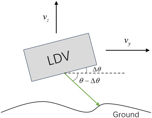
The velocity used by the proposed system in this paper is provided by LDV. The measuring principle of the LDV is as follows: the probe of the LDV emits a beam to the ground at a certain angle, and the velocity of the particles is calculated by measuring the Doppler shift information of the scattered light of the moving particles by using the Doppler effect (Zhou et al. Citation2014). When the ground is ideally flat, the northward velocity component of LDV is zero, and the error is also zero. When the ground has a certain slope, the LDV has a northward velocity component, and the beam emitted by the probe to the ground can be decomposed into the northward velocity and upward velocity
as shown in . Therefore, when considering the influence of slope on LDV velocity error, only northward and upward velocity errors need to be considered.
Figure 1. LDV operates on uneven surfaces.
The influence of different slope on LDV velocity error is analyzed. Assuming that the velocity of the vehicle is 20 m/s and the accuracy of LDV is 1 ‰, the relation between the slope and the velocity error of LDV northward and upward directions is shown in . From the , it is evident that the northward velocity error caused by uneven terrain is on the order of 10−2 m/s, while the upward velocity error is on the order of 10−3 m/s. The time required for the height error to reach 3 m is calculated based on the unidirectional divergence of the velocity error of the LDV. However, in practice, the velocity error is white noise, and the time required for the upward error divergence to reach 3 m is much longer than the calculated value in the table.
Table 1. The relationship between the ground scope and the velocity error of LDV.
1. The influence of attitude calculation error
The velocity of the LDV in the b frame needs to be converted into the velocity in the n frame through the direction cosine matrix calculated by inertial navigation, so the attitude error of inertial navigation will also affect the velocity error. Expand the second item to the right of EquationEquation (5)(5)
(5) , can be expressed as:
(6)
(6)
In EquationEquation (6)(6)
(6) ,
,
,
are the components of attitude error in the eastward, northward and upward directions respectively. The attitude error is mainly caused by gyro drift bg, and the relationship between the attitude error and gyro drift can be expressed as:
(7)
(7)
The Schuler angular frequency ≈ 1.24 × 10⁻³/s. From EquationEquations (6)
(6)
(6) and Equation(7)
(7)
(7) , it can be seen that gyro drift affects attitude error, which in turn influences the errors in eastward, northward, and upward velocities in the n frame. The influence of different gyro precisions on attitude error and velocity error is analyzed, as shown in .
Table 2. The relationship between gyro drift and LDV velocity error.
From , it is evident that when the gyroscope accuracy is 0.006°/h, the corresponding attitude error is 5″, and it takes 1.71 h for the height error to diverge to 3 m. In general, the measurement time for a single measuring line is less than 1.71 h, and the velocity error corresponding to the 5″ attitude error is 4.8 × 10⁻⁴ m/s, so the 5" attitude error meets the measurement requirements, and the corresponding gyroscope accuracy is 0.006°/h.
2.3. The direct impact of velocity error in the n frame on gravimetry
The velocity error part is extracted from the gravity error model in EquationEquation (3)(3)
(3) as shown in the following equation:
(8)
(8)
This paper mainly studies scalar gravity anomalies, so only vertical gravity anomalies are analyzed. Take the portion of the upward component in EquationEquation (8)(8)
(8) that includes the velocity error term, which can be expressed as:
(9)
(9)
In EquationEquation (9)(9)
(9) , the accuracy of gravimetry is affected by the eastward and northward velocity errors of the carrier. The direct influence of the north and east velocity errors on gravimetry at different driving velocities is analyzed below.
Due to the north-south distribution of the measurement lines for vehicle gravimetry, the velocity of the vehicle is concentrated in the north, and the northward velocity and velocity error are larger than those of the eastward. The influence of northward velocity error and eastward velocity error on gravimetry error is shown in .
Table 3. Influence of North velocity error on gravimetry error (unit: mGal).
Table 4. Influence of east velocity error on gravimetry error (unit: mGal).
It can be seen that when the northward velocity is 25 m/s and the velocity error is 0.2 m/s, the gravity anomaly caused is only 0.1566 mGal. When the eastward velocity is 15 m/s, the maximum gravimetry error does not exceed 0.3 mGal. In general, to improve the resolution of gravimetry, the driving velocity should not exceed 20 m/s, and the accuracy of the LDV is 1 ‰, resulting in a maximum velocity error of 0.02 m/s, which meets the requirements of gravimetry.
2.4. The indirect impact of velocity error in the n frame on gravimetry
If the position information obtained from the track calculation of the LDV velocity is used in gravity calculation, the velocity error will also cause the position error, ultimately affecting the accuracy of gravimetry. Extract the part of the scalar gravity anomaly error formula containing the position error:
(10)
(10)
The last term in EquationEquation (10)(10)
(10) is the error of normal gravity calculation, and the rest is the error of Eotvos correction term. The influence of position error on gravimetry is analyzed from two aspects of normal gravity calculation error and Eotvos correction error.
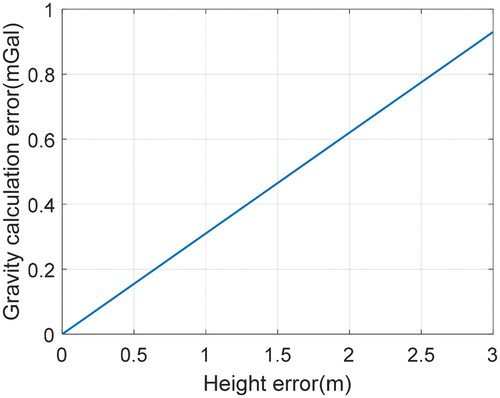
The relationship between height error and normal gravity calculation error can be expressed as:
(11)
(11)
In the EquationEquation (11)(11)
(11) ,
is the normal gravity calculation error,
is the height error,
It can be calculated that a height error of 3 m will cause a gravimetry error of about 1mGal. The simulation results are shown in the . Therefore, it is necessary to strictly control the height positioning error during the measurement process.
Figure 2. Relation between height error and gravity calculation error.
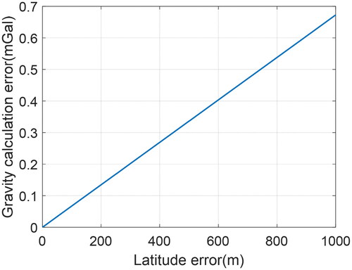
The impact of latitude error on the calculation error of normal gravity was analyzed through simulation. The calculation formula of normal gravity is based on the WGS-84 model, and the simulation results are shown in . It can be seen that even if the latitude positioning error is 1000 m, the resulting gravity calculation error does not exceed 0.7mGal, so the impact of latitude error can be ignored.
Figure 3. Relation between latitude error and gravity calculation error.
For the Eotvos correction term error, assuming the latitude error is 10 m, then =1.5679 × 10⁻⁶, and
=7.2921 × 10⁻⁵ rad/s, then
=1.1432 × 10⁻¹⁰, the error of the Eotvos correction term caused by latitude can be ignored. If the height error is 1 m, the height error
decayed by the denominator
and the magnitude reaches 10−14, can also be ignored.
2.5. Dimensional analysis of LDV
From the above analysis, the height error and vertical acceleration error caused by the measurement error of the LDV have a significant impact on the gravity anomaly, and the influence of different dimensions velocimeter on the two errors is also different. Therefore, the following mainly analyzes the one-dimensional (1D) and 2D-LDVs (Zhou et al. Citation2014; Gao et al. Citation2017; Wang et al. Citation2018a).
1D-LDV
Taking a single beam 1D-LDV as an example, it includes a measuring probe. Assuming the probe velocity is and the angle between its optical path and the ground is
the projection of the LDV velocity in the LDV coordinate frame (d frame) can be expressed as:
(12)
(12)
From EquationEquation (12)(12)
(12) , it can be seen that the z-axis component of the probe velocity in the d frame is 0. Due to the approximate overlap between the d frame and the b frame, the probe velocity cannot accurately capture the vertical velocity of the carrier, leading to potential errors in height and vertical acceleration measurements.
2. 2D-LDV
Similarly, taking the traditional 2D-LDV as an example. The two measuring probes of the LDV incident on the ground at the same inclination angle one in the forward direction and the other in the backward direction. The velocities of the two probes are
and
respectively. Therefore, the velocity of the LDV projected in the d frame can be expressed as:
(13)
(13)
From EquationEquation (13)(13)
(13) , it can be observed that the velocity of the 2D-LDV has a vertical component in the d frame, which can be sensitive to change in the upward direction and help minimize errors in height and vertical acceleration. Therefore, a high-dimensional LDV has more advantages in gravimetry.
Based on above analysis, in order to achieve a gravimetry accuracy better than 1 mGal, the system indicators should meet the requirements shown in .
Table 5. System standard.
3. Simulation and experiment
3.1. Simulation analysis
Based on theoretical analysis in the previous section, the impact of the accuracy of the LDV on gravimetry is simulated and verified. The simulation trajectory consists of three round trips, including six measurement lines (each round trip contains two measurement lines). During the simulation process, the carrier moves at a uniform velocity and remains at a constant height. The parameter settings and simulation trajectory are shown in and , respectively.
Figure 4. Simulation track.
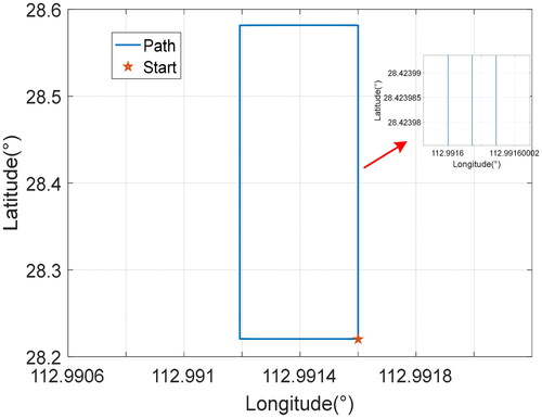
Table 6. Setting of simulation parameters.
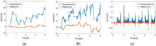
Integrate SINS with different precision LDV for navigation, and the positioning results are shown in . When using an LDV of precision 1 ‰, the maximum horizontal error is 3.15 m, and the maximum height error is 1.83 m, meeting the requirements of ; However, when using the LDV with an accuracy of 5 and 10, the height error and horizontal error both diverge to tens of meters, which cannot meet the requirements of .
Figure 5. Positioning error of SINS/LDV integrated gravimetry simulation system. (a) accuracy of the LDV 1 ‰; (b) accuracy of the LDV 5 ‰; (c) accuracy of the LDV 10 ‰.
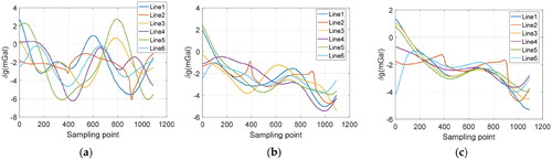
Furthermore, the simulation results of gravity anomaly calculation and processing are shown in . It is evident that the gravity anomaly of the measuring line with an accuracy of 1 ‰ is consistent with the trend of the added gravity anomaly. When the accuracy is 5 ‰, there is a relatively large local fluctuation in the gravity anomaly along the measuring line, but the overall trend remains consistent with the added gravity anomaly. However, when the accuracy is 10 ‰, the correlation between the gravity anomaly of the survey line and the trend of the added gravity anomaly is not strong.
Figure 6. Gravity anomaly simulation results of SINS/LDV. (a) accuracy of the LDV 1 ‰; (b) accuracy of the LDV 5 ‰; (c) accuracy of the LDV 10 ‰.
Evaluate the internal and external accord accuracy of the simulation line, and refer to for the results. When the LDV accuracy is 1 ‰, the total internal and external accord accuracy are 0.82 mGal and 0.89 mGal. When the accuracy is 5 ‰, the total internal and external accord accuracy are 3.34 mGal and 3.69 mGal. When the accuracy is 10 ‰, the total internal and external accord accuracy are 7.20 mGal and 8.15 mGal. By comparing the results, it can be observed that when the LDV accuracy is 1 ‰, the total internal and external accord accuracy is better than 1 mGal, which meets the requirements of gravimetry. However, when the LDV accuracy are 5 ‰ and 10 ‰, the total internal and external accord accuracy exceeds 1mGal, confirming the accuracy requirements of the LDV as outlined in .
Table 7. The accuracy evaluation result of SINS/LDV integrated gravimetry simulation system (unit: mGal).
3.2. Experimental verification
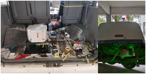
To verify the performance of the SINS/LDV integrated gravimetry system, a gravimetry experiment was conducted at Wanjiali Elevated in Changsha, Hunan Province, China. The SINS and 2D-LDV developed by our unit were selected as experimental equipment, and the data output frequency are both 100 Hz. The laser gyroscope inside the SISN has an accuracy better than 0.003°/h, the accelerometer has an accuracy better than 20 μg, and the velocimeter has a velocity measurement accuracy better than 1 ‰. The experimental vehicle was equipped with GNSS simultaneously. The results of SINS/GNSS integrated vehicle gravimetry system were used for comparison. The single point horizontal positioning accuracy of GNSS is 1.5 m, and the differential horizontal positioning accuracy is 0.4 m. The installation of the experimental equipment is depicted in .
Figure 7. Installation diagram of experimental equipment. 1-SINS; 2-navigation computer; 3-GNSS receiver; 4-GNSS antenna; 5-LDV.
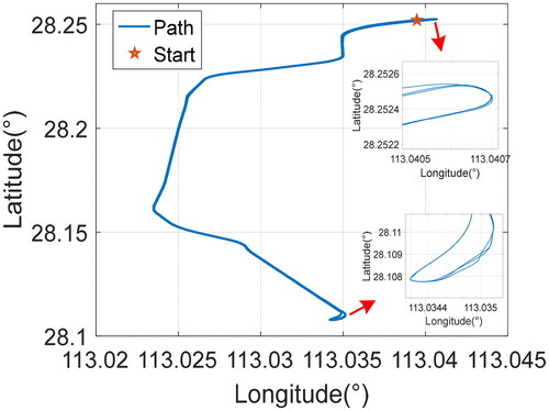
The experimental trajectory is shown in . The experimental measurement lines are mainly distributed in a north-south direction, and there are three back and forth measurement lines, with a total of six repeated measurement lines (one back-and-forth has two measurement lines). The length of a single line is about 17 km, and the entire journey is about 102 km.
Figure 8. Experimental track.
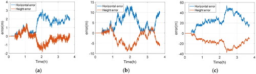
The experimental data has been analyzed and processed, and the positioning errors of each system are depicted in . The maximum horizontal error of the SINS/1D-LDV integrated gravimetry system is 30.54 m, and the height error is 2.68 m; The maximum horizontal error of the SINS/2D-LDV integrated gravimetry system is 7.51 m, and the maximum height error is 1.72 m. Since the velocity of LDV in the n frame is affected by the SINS attitude error, the position error of SINS/LDV is divergent. However, it can be seen from the analysis in section 2.2 that the measurement time of a single measurement line is much less than the time when the height error diverges to three meters, so the SINS/LDV system can meet the requirements of gravimetry. The horizontal and height errors of the SINS/GNSS integrated gravimetry system are basically less than 0.5 m, indicating that the positioning accuracy of this reference system is relatively high.
Figure 9. Positioning error of gravimetry system. (a) SINS/1D-LDV; (b) SINS/2D-LDV; (c) SINS/GNSS.
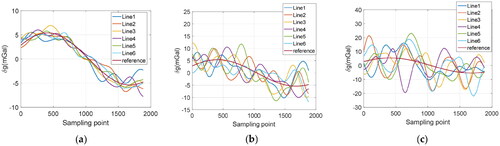
The data collected by the systems were used to calculate gravity anomaly and to obtain the measurement results of the SINS/LDV, SINS/GNSS integrated gravimetry system, as shown in . The results in the figure indicate a significant difference in the variation trend between the lines based on the SINS/1D-LDV integrated gravimetry system. The variation trend between the lines based on the SINS/2D-LDV integrated gravimetry system is relatively consistent, while the SINS/GNSS integrated gravimetry system has the best results (Tang et al. Citation2013).
Figure 10. Gravity anomaly measurement results. (a) SINS/1D-LDV; (b) SINS/2D-LDV; (c) SINS/GNSS.
The paper only conducts internal conformity accuracy evaluation due to the inability to establish external reference points for elevated structures (Guo et al. Citation2008; Wang et al. Citation2018b). The system’s evaluation results are presented in .
Table 8. The Internal accord accuracy of gravimetry system (unit: mGal).
From , it can be observed that the maximum internal accord accuracy of a single measurement line based on the SINS/1D-LDV integrated gravimetry system is 2.21 mGal, the minimum is 0.92 mGal, and the total internal accord accuracy is 1.50 mGal; The maximum internal accord accuracy of a single measuring line based on SINS/2D-LDV integrated gravimetry system is 0.87 mGal, the minimum is 0.53 mGal, and the total internal accord accuracy is 0.68 mGal; The maximum internal accord accuracy of a single measuring line based on the SINS/GNSS integrated gravimetry system is 0.74 mGal, the minimum is 0.31 mGal, and the total internal accord accuracy is 0.54 mGal. Among the three systems, the internal accord accuracy of the SINS/2D-LDV is relatively close SINS/GNSS integrated gravimetry system and better than 1 mGal, indicating the feasibility of the SINS/2D-LDV integrated gravimetry scheme. The internal accord accuracy of the SINS/2D-LDV integrated gravimetry system is improved by about 0.82 mGal compared to SINS/1D-LDV system, indicating the necessity of selecting a high-dimensional LDV. The experiment has proven that when the GNSS signal is blocked, the SINS/2D-LDV integrated method can also achieve vehicle gravimetry with an accuracy better than 1 mGal.
4. Conclusions
This paper aims to address the limitation of current vehicle gravimetry by studying the error characteristics and feasibility of proposed SINS/LDV integrated gravimetry system. At the same time, the error characteristics of the system are analyzed and the system index is proposed. Simulation results of the SINS/LDV integrated gravimetry system under different accuracies of LDV show that when the LDV accuracy is 1 ‰, the internal and external accord accuracy of the system is better than 1 mGal, the accuracy requirements for the LDV in the SINS/LDV integrated gravimetry system. The vehicle experiment on SINS/LDV integrated gravimetry system with different dimensions LDV have demonstrated that the accuracies of SINS/2D-LDV and SINS/GNSS integrated gravimetry systems are better than 1 mGal. In contrast, the internal accord accuracy of SINS/1D-LDV integrated gravimetry systems is relatively poor. It not only shows the feasibility of SINS/LDV integrated gravimetry system, but also shows the necessity of the dimension of LDV. The research presented in this paper demonstrates that the SINS/2D-LDV integrated gravimetry system can autonomously conduct continuous dynamic gravimetry even when GNSS signals are blocked. This system can provide technical assistance for geological exploration, gravity matching, and refinement of local gravity fields in environments such as tunnels, caves, and jungles.
Disclosure statement
No potential conflict of interest was reported by the author(s)
Additional information
Funding
References
- Ai W, Zhong S, Leng Y, Wang S. 2023. A real-time autonomous gravity measurement method for underwater gravity-aided navigation. IEEE Access. 11:135728–135737. doi: 10.1109/ACCESS.2023.3338537.
- Bruton AM. 2001. Improving the accuracy and resolution of SINS/DGPS airborne gravimetry. ProQuest Dissertations and Theses Global. University of Calgary.
- Cai S, Cao J, Yu R, Xiong Z, Guo Y, Yang B. 2022. Dynamic error elimination method for strapdown dynamic gravimetry. IEEE Geosci Remote Sensing Lett. 19:1–5. doi: 10.1109/LGRS.2022.3168063.
- Fok H, He Q. 2018. Water level reconstruction based on satellite gravimetry in the Yangtze River Basin. IJGI. 7(7):286. doi: 10.3390/ijgi7070286.
- Fu Q, Liu Y, Liu Z, Li S, Guan B. 2018. High-accuracy SINS/LDV integration for long-distance Land Navigation. IEEE/ASME Trans Mechatron. 23(6):2952–2962. doi: 10.1109/TMECH.2018.2875151.
- Gao C, Wang Q, Wei G, Long X. 2017. A highly accurate calibration method for terrestrial laser doppler velocimeter. IEEE Trans Instrum Meas. 66(8):1994–2003. doi: 10.1109/TIM.2017.2685078.
- Gao J, Li K, Chen J. 2020. Research on the integrated navigation technology of SINS with couple odometers for land vehicles. Sensors. 20(2):546. doi: 10.3390/s20020546.
- Golovan AA, Klevtsov VV, Koneshov IV, Smoller YL, Yurist SS. 2018. Application of GT-2A gravimetric complex in the problems of airborne gravimetry. Izv, Phys Solid Earth. 54(4):658–664. doi: 10.1134/S1069351318040043.
- Grigoriadis VN, Andritsanos VD, Natsiopoulos DA. 2023. Validation of recent DSM/DEM/DBMs in test areas in Greece using spirit leveling, GNSS, gravity and echo sounding measurements. IJGI. 12(3):99. doi: 10.3390/ijgi12030099.
- Guo ZH, Xiong SQ, Zhou JX, Zhou XH. 2008. A research on data quality evaluation method of repeat lines in airborne gravity survey. Chin J Geophys. 51(5):1093–1099.
- Kaban MK, Schwintzer P, Tikhotsky SA. 1999. A global isostatic gravity model of the Earth. Geophysical Journal International. 136(3):519–536. doi: 10.1046/j.1365-246x.1999.00731.x.
- Li X, Jekeli C. 2008. Ground-vehicle INS/GPS vector gravimetry. Geophysics. 73(2):I1–I10. doi: 10.1190/1.2821155.
- Majumdar TJ, Chander S. 2011. Simulation of SARAL (Satellite with ARgos and ALtika) resolution gravity over the western Indian offshore for geological/structural interpretation. Geocarto Int. 26(1):21–34. doi: 10.1080/10106049.2010.535617.
- Sun S-B, Yan J-G, Gao W-T, Wang B, Wang Z, Ye M, Barriot J-P. 2023. Simulated gravity field estimation for the main belt comet 133P/Elst-Pizarro based on a satellite-to-satellite tracking mode. Res Astron Astrophys. 23(9):095012. doi: 10.1088/1674-4527/acdc89.
- Tang K, Wang J, Li W, Wu W. 2013. A novel INS and doppler sensors calibration method for long range underwater vehicle navigation. Sensors . 13(11):14583–14600. doi: 10.3390/s131114583.
- Wang Q, Gao C, Zhou J, Wei G, Nie X, Long X. 2018a. Two-dimensional laser Doppler velocimeter and its integrated navigation with a strapdown inertial navigation system. Appl Opt. 57(13):3334–3339. doi: 10.1364/AO.57.003334.
- Wang W, Gao J, Li D, Zhang T, Luo X, Wang J. 2018b. Measurements and accuracy evaluation of a strapdown marine gravimeter based on inertial navigation. Sensors. 18(11):3902. doi: 10.3390/s18113902.
- Wu M, Yin X. 2020. Research on error correction algorithm of vehicle SINS and odometer integrated navigation. J Phys: conf Ser. 1544(1):012019. doi: 10.1088/1742-6596/1544/1/012019.
- Wu M, Zhang K, Cai S, Cao J, Wang M, Wang L, Yu R. 2017. A new method for land vehicle gravimetry using SINS/VEL. Sensors. 17(4):766. doi: 10.3390/s17040766.
- Xiong Z, Cao J, Wu M, Cai S, Yu R, Wang M. 2020. A method for underwater dynamic gravimetry combining inertial navigation system, doppler velocity log, and depth gauge. IEEE Geosci Remote Sensing Lett. 17(8):1294–1298. doi: 10.1109/LGRS.2019.2945628.
- Yu R, Cai S, Wu M, Cao J, Zhang K. 2015. An SINS/GNSS ground vehicle gravimetry test based on SGA-WZ02. Sensors . 15(9):23477–23495. doi: 10.3390/s150923477.
- Zhao L, Wu M, Forsberg R, Olesen A, Zhang K, Cao J. 2015. Airborne gravity data denoising based on empirical mode decomposition: a case study for SGA-WZ greenland test data. IJGI. 4(4):2205–2218. Voldoi: 10.3390/ijgi4042205.
- Zhou J, Nie X, Lin J. 2014. A novel laser Doppler velocimeter and its integrated navigation system with strapdown inertial navigation(Article). Opt Laser Technol. 64:319–323. doi: 10.1016/j.optlastec.2014.06.001.