
 ?Mathematical formulae have been encoded as MathML and are displayed in this HTML version using MathJax in order to improve their display. Uncheck the box to turn MathJax off. This feature requires Javascript. Click on a formula to zoom.
Abstract
Although engineers can analyse demanding structures, basic understanding of the structural behaviour is not always clear to them. This is particularly true with cable-stayed bridges having asymmetric spans and inclined or even curved towers. To improve this situation, the present paper with a new simple design approach method is introduced. The method is useful at the conceptual design stage, when only the geometry of the bridge and the approximate weight of the main span is known or easily estimated. No deeper-going computer analysis is needed, but knowledge of basic graphic statics is required. In the paper, analytic formulae are derived for the cable quantity and balancing loads needed. Only harp-type cable-stayed bridges are discussed. The approach is based on the so-called force–length method and curtain cables. The formulae are useful when comparing alternative bridge solutions, or when determining the back-span cable forces and balancing weights needed, especially with curved towers.
Introduction
The history of graphic statics identifiably begins with a study published by Varignon in 1725. However, it was no earlier than the 1860s that Maxwell and Cremona developed a method of graphic statics, as explained in Ref. [Citation1]. A significant milestone is the book by Culmann entitled “Die Graphische Statik”.Citation2 Ref. [Citation3] continued the work of Culmann.
In clear, straightforward pylon shapes, traditional drawing technique – to illustrate the force flow – serves as a quick tool for preliminary design. When studying curved-tower structures with precise geometry, the drawing technique in its traditional form does not produce results accurate enough, but by applying graphic statics, together with vector algebra and analytical statics, the accuracy problem is solved.
Recent developments in computer-aided design provide opportunities for optimal structural shape design interactively. Full benefits of programs like RhinoVAULT can be utilised assuming that the designer knows the basic principles of structures and is able to interact with software.Citation4
There are several examples of unconventional tower bridges that have provoked severe argumentation because of their shape, and still do. The most well known of them is the Alamillo Bridge in Seville, which has no back-span cables in spite of having an inclined tower.Citation5 Other recent examples are the Erasmus Bridge in Rotterdam, the Samuel Becket Bridge in Dublin, the Langer See Footbridge at Böblingen/Sindelfingen and the Yamuna Bridge in New Delhi.Citation6–9
This paper demonstrates the use of the so-called force–length method. Analytic results are derived for the force–lengths of cables, towers and stiffening girder, respectively, with variable span-length relations, tower heights and tower inclinations. Material quantities and costs are also calculated using the formulae shown in the paper. A calculated example demonstrates the use of the derived analytic formulae valid for harp-type cable-stayed bridges with inclined towers. Numeric examples for curved-tower bridges using graphic statics and vector algebra are calculated.
Load Balancing for Permanent Loads
The main target of this paper is to show how the bending moments due to permanent loads are eliminated and the whole cable-stayed bridge can be effectively balanced in a simple way. For this, the stay-cables are firstly assumed to be located side by side so that a continuous curtain structure is formed. In reality, however, the anchoring points of the cables are apart from each other, which causes negligible local bending. In the preliminary design phase, their effect on costs, however, can be ignored. At this stage, no computer-based analysis of the bridge is needed, but the estimation of stresses caused by the permanent loads is required. Here, experience from earlier bridges helps a lot.
Balancing of an Inclined-Tower Bridge
The balance of an inclined-tower bridge can be drawn or calculated applying the Cremona–Maxwell method. The process starts from the preliminary design of the main-span cross section. Thereafter, the cable forces and counterweights needed at the back-span are obtained by vector calculation.
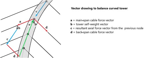
Minimisation of the bending moments in the deck due to permanent loads requires that the stay-cable forces are such that no deflection of the stiffening girder occurs at the cable anchoring points, i.e. that the girder is supported on unsettled intermediate bearings. The corresponding support reactions, designated here as equivalent weight vectors gm, define the main-span cable force vectors a, as shown in the vector drawing of . Correspondingly, in the tower, the back-span force vector d guides the resultant tower force vector c and makes it follow the axis of the tower. Finally, the back-span cable force is balanced by the adjusted back-span deck weight vector gb, as shown in . Related to this topic, a real example is shown in .
Fig. 1: Vector drawing of a backwards-inclined-tower bridge
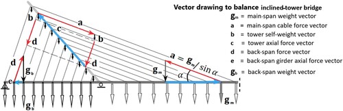
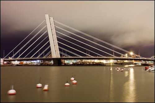
Fig. 2: The Crusell Bridge, Helsinki, designed by WSP Finland Oy retrieved from https://www.vastavalo.net/ © Antti Pulkkinen
Analytical Solution for Inclined-Tower Cable-Stayed Bridges
In classic publications,Citation10,Citation11 simple formulae to estimate the tower height and recommended span-length relations for traditional two-tower bridges are given. This study, however, gives formulae that can be applied in the general case. Here, the span-length relation and tower height can be freely chosen, and tower inclination both backwards or forwards is allowed. Equivalent results have not been published in the literature before, although several FEM-calculation cases of cable-stayed bridges can be found, for example in Refs. [Citation12,Citation13].
Force–Length Calculations
The calculations below are based on the force–length method, defined by equation
(1)
(1) where Fi is the member axial force of the load balanced structure,
is the member length, and n is the number of members covered. When the uniform loads are given using the units MN/m and the lengths are in metres, the units of the force–length are MNm.
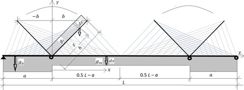
The structure studied is a harp-type bridge with curtain-like cables. The basic data needed are the uniform load of the main span gm due to dead weight and the lengths L, a, b and h indicated in .
Fig. 3: Inclined-tower, harp-type cable-stayed bridge
The force–length of the main-span cables are calculated as follows.
The height of the anchoring point y(x) is
(2)
(2) and location b(x) of the anchoring point is
(3)
(3)
Furthermore, the length l(x) of the respective stay cable is
(4)
(4) where L is the total length of the cable-stayed bridge discussed, and the corresponding cable force F(x) is
(5)
(5)
Thus, the force–length of the main-span cables is
After integration, the formula for the main-span cable force–length can be written as
(6)
(6)
The force–length of the back-span cables, as a function of x, can be solved correspondingly. Consequently, the cable force multiplied by the cable length leads to equation
(7)
(7) from which the formula of the force–length of the back-span cables can be written as
(8)
(8)
Finally, because the length of the tower h(x) from the bottom to the cable anchorage height is
(9)
(9) and the tower axial force F(x) due to cable forces is
(10)
(10) the force–length
(11)
(11) leads to the tower force–length
as
(12)
(12)
Equation (12) does not include the force–length related to the self-weight of the tower given in Eq. (14).
The force–length of the stiffening girder of the whole bridge, assuming that the fixed bearing of the girder is located at an abutment while the other bearings are movable, can be expressed as
(13)
(13)
The first two terms represent the force–lengths of the whole stiffening girder due to the main-span cables. The negative third term is due to the horizontal component of the back-span cables. Finally, the fourth term is due to the horizontal component of the tower support reaction caused by the cables.
Summing the results of Eqs. (6) and (8) leads to the same force–length result as the sum of Eqs. (12) and (13).
The force–lengths calculated from the tower self-weight are as follows.
The force–length of the back-span cables calculated from the uniformly distributed self-weight
of the tower, is
(14)
(14)
Respectively, the force–length of the self-weight of the towers is
(15)
(15) and the force–length
of the back-span girders due to the tower self-weight is
(16)
(16)
Finally, the total force–length of the bridge cables is obtained as the sum of Eqs. (6), (8) and (14). Thus,
(17)
(17)
Correspondingly, the force–length of the towers is obtained as the sum of the force–lengths expressed in Eqs. (12) and (15). Thus,
(18)
(18)
Finally, the force–length of the whole stiffening girder is obtained as the sum of the force–lengths expressed by Eqs. (13) and (16). Thus,
(19)
(19)
The force–lengths of a single-tower bridge can be calculated using those of a two-tower bridge whose main span is twice that of the single-tower bridge, while the back spans are equal. Thus, if the single-tower bridge spans are a + c, then the spans of the corresponding two-tower bridge are a + 2c + a. The results obtained should be divided by two.
Costs of Cables and Towers
The force–length of the bridge cables divided by the stress and multiplied by the unit weight gives the quantity of the cable material. If the unit price is known, then also the costs of the cables are known. Thus,
(20)
(20) where
is the unit weight of cables, us is the unit price of the material and σs is the stress used.
If only the volume is needed, as is the case when the quantity of tower concrete is of interest, the calculation of the unit weight can be omitted. The costs of tower require at first the calculation of the volume of tower material using the formula (12). The self-weight gt, needed in formula (15), can then be calculated. The cost of the concrete towers is
(21)
(21) where uc is the unit price of concrete per cubic metre and σc is the stress used for permanent loads.
Costs of Stiffening Girder
Below, the costs of different design alternatives for the stiffening girder are discussed, but considering only the cost of cables and towers. This restriction should be acceptable when only the cost differences due to tower shape are compared. Here, the main-span length of the bridge, the type of the stiffening girder and its ability to resist compression play an important role. If the girder is made from concrete and the span of the bridge is moderate, lower costs are obtained owing to compression caused by the stay-cables. But in long-span bridges, owing to high axial compression near the tower, additional costs are incurred. This is partly valid for a composite deck as well, although compression helps in crack elimination. With long spans, however, this positive effect turns out to be a negative one, because the deck-slab thickness has to be increased near the tower because of high compression, see for example the Yamuna bridge in New Delhi.Citation7
Costs of Balancing Weight
If balancing loads are not used in the back span of an asymmetric bridge, then intermediate supports or additional prestressing are needed. This will entail additional costs. In this study, the balance is accomplished by additional concrete weights. Here, the balanced deck weight at the back span is
(22)
(22) It is assumed that the weight
is uniform throughout the whole girder.
The weight of the balancing load in the whole bridge is
(23)
(23)
The volume of the concrete in the bridge is
(24)
(24) where
denotes the unit weight of concrete per cubic metre.
It is assumed that the weight is uniform throughout the whole girder. This quantity is not included in the balancing concrete weight calculated in Eqs. (20) and (21).
Example Calculation for an Inclined Tower Bridge
A two-tower cable-stayed bridge as depicted in is studied using the following numerical
values: L = 500 m, a = 100 m and h = 90 m. The weight of the bridge deck gm in the main span is 0.3 MN/m. For the permanent load, the stress σs in the cables is +600 MPa, and in the concrete tower σc is −10 MPa. The unit weight of the cables is 7850 kg/m3 and the unit weight
of concrete is 0.025 MN/m3.
The uniform self-weight of tower concrete can be calculated using Eqs. (12), (13), (14) and (15). When the tower inclination tan α is −1, the unit weight of the tower
attains the value 0.42 MN/m.
When the tower inclination tan α is −1, the cable quantity Q, calculated using Eqs. (6), (8) and (14), is
(25)
(25)
The third term is due to the decreased cable quantity caused by the weight of the backwards inclined tower. The calculated cable quantity of the bridge, in relation to the tower inclination tan α, is shown in .
Fig. 4: Cable quantity and relative costs of cables, tower and balancing concrete
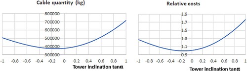
The relative cost C of the cables, the towers and the balancing concrete is calculated using the following unit prices: 20 €/kg for the cables, 1500 €/m3 for the tower concrete, and 500 €/m3 for the balancing concrete. Thus,
(26)
(26)
The relative costs of the example bridge, in relation to tower inclination, are shown in .
Compared to a corresponding vertical-tower bridge, an inclination of 45° backwards increases the cable quantity by 34.4%. Correspondingly, the cost is increased by 26.2%.
Balancing of a Curved-Tower Bridge
The elimination of bending moments in the tower requires that the axial force resultant follows the tower axis. To obtain such a positive situation, the correct back-span cable forces need to be found. A way to do this is shown in . Additionally, it is worth of noticing that, although a curved tower as a whole is moment-free, minor local bending moments, however, remain in the areas between the nodal points. Even these minor local bending moments could be avoided if a small local curvature were given to the tower.
Fig. 5: Curved-tower vector drawing
If the back-span cable forces require balancing weight, it can be arranged, for instance, by using heavy gross girders or a thicker concrete deck slab in the case of a composite structure.
Curved-Tower Bridge Examples
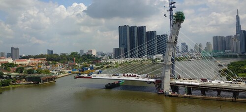
In this section, a comparative study of curved-tower bridges is presented. The calculations are carried out by first solving the stay-cable node coordinates of the bridge. Then the forces of each main-span cable are determined on the basis of the estimated weight of the stiffening girder. Finally, the back-span cable forces and respective counterweights are calculated as shown in . The results obtained for curved-tower bridges are compared with those of vertical-tower bridges and inclined-tower bridges, respectively. The example bridges are asymmetric single-tower bridges, like the one shown as an example in .
Fig. 6: The Thu Thiem II Bridge, Ho Chi Minh City, designed by WSP Finland Oy (photo courtesy of Thang Anh)
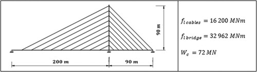
In all calculations, the span-length relation 90 m/200 m = 0.45 is used. The corresponding value in a two-tower bridge would be 0.225. Such span-length relations lead to remarkable balancing loads at the back span. The dimensions of the bridges studied are close to those of real bridges. The curvature of the tower is a circle and the tower axis at the footing is perpendicular to the horizontal stiffening girder axis.
Four different tower inclinations are studied: 15° or 30° backwards or forwards, respectively. In each alternative, the height level of the tower tip is 90 m. The length of the tower increases when the inclination increases. The main-span cables are parallel, which leads to non-parallel back-span cables, because the cable–anchorage distances at the back span are equal. The main-span deck weight is 0.2 MN/m and the weight of the tower is 0.3 MN/m. shows the main dimensions and the calculated force–lengths of the vertical-tower bridge studied.
Fig. 7: Vertical-tower bridge used in comparisons between the respective curved-tower bridges
The results for the four curved- and inclined-tower bridges are shown in . The ratios of the force–lengths to those to the vertical-tower bridge are shown also in . Only the layout drawings of the curved-tower bridges are shown.
Fig. 8: Four curved single-tower bridges used in the comparisons
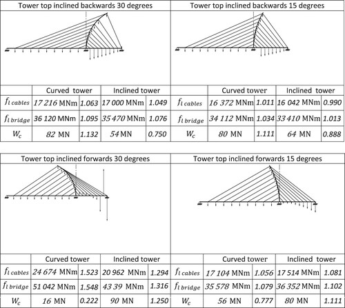
The calculations show that a backwards-curved tower with an inclination of 30° increases the costs of cables, tower and stiffening girder by 9.5% compared to that of the vertical-tower bridge. The increase of cable quantity is only 6.3%. If the tower is inclined forwards, the increase of cable quantity is 52.3% compared to the amount of the vertical-tower bridge. (The values are not directly comparable with the results given in because of different span relations and tower height.)
reveals that the counterweight at the back span of backwards-curved-tower bridges increases when approaching the tower. This is due to the fact that, the lower are the cable anchorages, the bigger are the back-span cable forces needed to guide the increased tower axial force to the next node.
When the balancing requires that the back-span girder cross section needs to be changed, the neutral axis of the stiffening girder should, however, remain unique in order to avoid bending in the girder.
Conclusions
Analytic calculations using force–lengths and curtain cables enables the costs to be estimated of variable layouts of cable-stayed bridges already at an early design stage. In this paper, analytical solutions for inclined towers are presented. The equations given are useful when comparing alternative layouts. Theoretically, the minimal cost is obtained by inclining the tower slightly backwards. Concrete should be preferred for towers with backwards inclination and steel for towers with forwards inclination, respectively. The weight of a backwards inclined tower has no influence on the main-span cable forces.
For a tower having backwards curvature, the lower the back-span cable is located, the bigger is the cable size needed. Correspondingly, more balancing load is needed near the tower than further away. As a final remark, it can be stated that the additional costs due to tower inclination and curvature can be kept to an acceptable level if the balance of the bridge is properly designed and the tower’s deviation from the vertical is not excessive.
The results are based on analytical calculations in which the stay cables are described as continuous curtain-like structures. The results of the material quantity and cost calculations performed are so close to the respective results for real constructed bridges that the calculations presented here can be considered as a sufficiently reliable method for preliminary design.
Correction Statement
This article has been corrected with minor changes. These changes do not impact the academic content of the article.
References
- Rippmann H. Funicular Shell Design: Geometric approaches to form finding and fabrication of discrete funicular structures. Doctoral Thesis, ETH Zurich. 2016. doi:10.3929/ethz-a-010656780.
- Culmann K. Die Graphische Statik, Meyer & Zellner, Eth- Bibliotek Zurich. 1866. doi:10.3931/e-rara-20052.3652.4.1.1.
- Ritter W. Anvendung der graphischen Statik nach Professor Dr. C. Culmann (Use of Grafic Statics according to Professor Doctor C. Culman), Verlag von Meyer & Zeller. ETH- Bibliotek Zurich; 1888. doi:10.391/e-rara-20067.
- Schrems M, Kotnik T. Statically motivated form-finding based on extended graphical statics. Proceedings of the 18th International Conference on Computer- Aided Architectural Research in Asia. 2013;843–852.
- Orr J. A critical analysis of Santiago Calatrava’s Puente del Alamillo, Seville. Proceedings of Bridge Engineering 2. Conference 2008, University of Bath. https://2008//people.bath.ac.uk/jjo20/Dr_John_Orr/Publications_files/ORR%20PAPER%2001.pdf.
- Reusink J, Kuijpers M. Design of Erasmus Bridge, Rotterdam. Struct Eng Int. 1998;8(4). doi:10.2749/101686698780488795.
- Cutter J, Flanagan J. Samuel Beckett Bridge Dublin, Ireland. Bridge Eng. 2011;164(3). doi:10.1680/bren.2011.164.3.133.
- Keil A, Waldraft T. Die Harfenbrücke über den Langen See (The Harbour Bridge over the Langen Sea): Ein Werkbericht über die neue Fuss- und Radwegbrücke auf dem Flugfeld Böblingen/Sindelfingen (A Working Report of the New Pedestrian and Cycleway Bridge at the Böhlingen/Sindelfingen Airport). Stahlbau. July 2017;86(7):632–637.
- Schlaich M, Subbarao H, Kurian J. A signature cable-stayed bridge in India – The Yamuna Bridge at Wazirabad in New Delhi. Struct Eng Int. 2013;233(1). doi:10.2749/101686613X13363929988179.
- Leonhardt F, Zellner W. Cable-Stayed Bridges, IABSE PERIODICA.1980; 2.
- Gimsing N, Georgakis C. Cable supported bridges: concept and design. 3rd edn. Wiley: Chichester; 2012; ISBN:978-0-470-66628-9.
- Lute V, Upadhyay K, Singh K. Genetic algorithms – based optimum of cable stayed bridges. J. Soft. Eng. and App. 2011;4(10). doi:10.4236/jsea.2011.410066.
- Hassan, M. Optimization of stay cables in cable-stayed bridges using finite element, genetic algorithm, and B-spline combined technique. Eng. Struc. 2013;49:643–654. doi:10.1016/j.engstruct.2012.11.036.