
1. Introduction
The dentinal tissue is the main hard tissue of the tooth and thus the main anchorage tissue in any dental restorative procedure.
Dentin is a porous media with a specific architecture that is a heritage from its genesis. Hollow tubes called tubules (made of a lumen and a highly mineralized peritubular collar called PTD) are passing through the tissue of intertubular dentin (ITD, a composite mainly made of collagen fibrils and hydroxyapatite crystals). Tubules are linked together by smaller channels.
Its microstructure has been widely investigated in 2 D at the microscale but the knowledge of its 3 D micro- and nano-structure, their gradients and the structure-properties relationship is still incomplete.
In this paper, we will illustrate why the use of FIB-SEM technique can be useful to shed a new light on the dentinal tissue. We will illustrate 3 D imaging using FIB-SEM and we will discuss how it can be useful to machine samples for in-situ mechanical testing or future (HR)TEM imaging.
2. Methods
2.1. Sample preparation
The samples used in this study are sound human third molars. The teeth were collected, cleaned of soft tissue, stored at 4 °C in a solution of 1% chloramine-T, and used within 3 months. Slices of dentin of roughly 1 mm were prepared and polished (with 800, 1200, 2400 and 4000 grit sandpaper). They were gold sputtered prior to SEM imaging.
2.2. FIB-SEM 3D imaging
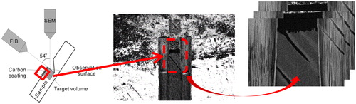
Image acquisition was performed by using a FIB-SEM (FEI Helios NanoLab 660). Three areas (near DEJ, in middle dentin and in predentin) were acquired using the “Slice and View” mode () in back-scattered electron (BSE) collection mode to obtain an image of the chemical contrast. The typical size of a studied area is (20 µm)3 and the distance between two slices is 20 nm.The image treatment and analysis were performed using ImageJ.
Figure 1. FIB-SEM “slice and view” principle.
2.3. FIB machining
FIB-SEM can also be used to machine samples prior to mechanical testing or (HR)TEM imaging. In this study, a tensile test sample has been machined with FIB and manipulated by using a nanomanipulator, ion beam induced platinum deposition and a piezoelectric rotary motor. We will discuss further investigations of the nanostructure using (HR)TEM.
3. Results and discussion
3.1. FIB-SEM 3D imaging
illustrates the 3 D microstructure obtained after image treatment.
Figure 2. 3D visualization of the area in middle dentin. In red, the tubules’ lumen and channels. In blue, the PTD. ITD is not represented.
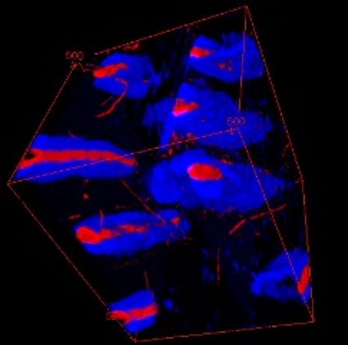
Image treatment was difficult when the sample was located in predentin or near DEJ. For predentin, the main problem was that the dentin, which is mainly organic at this location, presents odontoblastic processes in the tubule lumens and those odontoblastic processes are difficult to separate from the dentinal tissue. Near DEJ, as the volume investigated is small, very few tubules and channels are imaged. Nevertheless, the parameters obtained that are summarized in are in accordance with the literature and the technique enables an interesting visualization of channels between tubules. The measure of those channels dimensions is more realistic than those made by CLSM (Vennat et al. Citation2017).
Table 1. Results of image analysis for the three considered areas.
Microstructural parameters can be assessed using this technique as with ptychography (Zanette et al. Citation2015), but here the area considered is not a representative elementary volume. Indeed, in a reasonable amount of time, only 8 tubules can be imaged. So, it can be imagined lowering the resolution to get information only on tubules and ITD on a larger area (and loose the information on channels and on ITD nano-structure i.e., entanglement of collagen fibrils and crystals). It can also be interesting to focus only on ITD and resolve the entanglement of collagen fibrils and crystals, it has never been done using this technique to the authors’ knowledge.
This 3 D visualization can also be done after mechanical testing on a micro-pillar. The machining and testing of micropillar using FIB-SEM and then a nanoindentor is an interesting technique (Han et al. Citation2012) and we think that a final step of 3 D visualization of the sample after testing will enable to better understand the crack propagation in dentin.
3.2. FIB-SEM machining
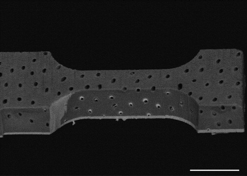
A sample for microtensile test has been successfully machined using FIB-SEM (). This sample can further be used to do in-situ testing. A limitation of this test will be that it will be performed on a dehydrated sample. But we argue that it may however contribute to understand the structure-properties relationship of dentin.
Figure 3. Sample for microtensile test (scale bar: 20 µm).
With the same procedure than the first step of microtensile sample machining a TEM sample can be machined in order to observe the nano-structure of dentine using (HR)TEM. It will bring a new insight into the arrangement of collagen fibrils and hydroxyapatite crystals as it has been revealed in bone by Grandfield et al. (Citation2018).
4. Conclusions
FIB-SEM can be used to image and machine dentin in an unprecedented way. The complexity of dentin hierarchical structure can be revealed using FIB-SEM “Slice and View” technique in addition to TEM examination that can be done on a FIB-SEM milled sample.
In situ testing of dentin can also be achieved. Here, we presented a sample machined by FIB-SEM prior to testing. An in-situ machine will be used to perform a tensile test on it. As this test will be performed under SEM, the sample will be dehydrated. To avoid this bias, we also plan to perform test outside the SEM on rehydrated dentin micropillars (machined by FIB) loaded using a nanoindentor.
Additional information
Funding
References
- Grandfield K, Vuong V, Schwarcz HP. 2018. Ultrastructure of bone: hierarchical features from nanometer to micrometer scale revealed in focused ion beam sections in the TEM. Calcif Tissue Int. 103(6):606–616.
- Han CF, Wu BH, Chung CJ, Chuang SF, Li WL, Lin JF. 2012. Stress–strain analysis for evaluating the effect of the orientation of dentin tubules on their mechanical properties and deformation behavior. J Mech Behav Biomed Mater. 12:1–8.
- Vennat E, Wang W, Genthial R, David B, Dursun E, Gourrier A. 2017. Mesoscale porosity at the dentin-enamel junction could affect the biomechanical properties of teeth. Acta Biomater. 51:418–432.
- Zanette I, Enders B, Dierolf M, Thibault P, Gradl R, Diaz A, Guizar-Sicairos M, Menzel A, Pfeiffer F, Zaslansky P. 2015. Ptychographic X-ray nanotomography quantifies mineral distributions in human dentine. Sci Rep. 5(1):9210.