
 ?Mathematical formulae have been encoded as MathML and are displayed in this HTML version using MathJax in order to improve their display. Uncheck the box to turn MathJax off. This feature requires Javascript. Click on a formula to zoom.
1. Introduction
In this paper the stress distribution of a complete assembly of bovine hip is investigated through the finite element method (FEM) with realistic boundary conditions. To determine influence of various constitutive assumptions on obtained results, we compared field of stresses and their principal directions in three cases: (i) bone with isotropic cortical and cancellous tissues, (ii) cancellous bone with orthotropic properties specified with respect to the global coordinate system, (iii) cancellous bone with orthotropic properties and material frame oriented accordingly to the fabric tensor. In all case the cortical bone was supposed to be isotropic.
2. Methods
2.1 Mechanical properties of bone
Local isotropic and anisotropic material properties for spongy tissue were obtained using the model proposed by Zysset and Curnier (Citation1995):
where:
ρ = f(BV/TV) – density function of bone volume fraction, mi – fabric tensor eigenvalues (for isotropic mi=1), E0, ν0, G0 – tissue properties (from experiments), andk, l – exponents for density and fabric (from experiments).
The value of parameters E0, ν0, G0, k, l were determined based on the comparison of FEM results and experimental data in accordance with the methodology presented by Gross et al. (2013).
2.2 Skeleto-muscular model
In order to guarantee realism of simulations, a skeleto-muscular model of bovine hind limb was constructed, with the most important muscles connecting specific bones. Only such model of complete limb could provide realistic loads to the femur in the hip joint area (Zadpoor and Weinans Citation2015). Skeleto-muscular model gives a possibility to provide stress changes for dynamic loads during motion. The geometry of the femur was obtained from experimental μCT data. All muscles were represented by truss elements connecting the points of their attachments. To avoid artificial stress concentration in attachment areas, additional layers of elements were created to act as tendons and/or cartilages. All steps of the skeletomuscular model construction are presented in .
Figure 1. Model of the skeleto-muscular system of the hind limb in bovine.
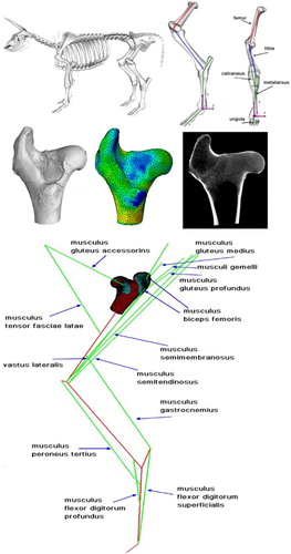
The bar elements representing the muscles were assigned with properties of changing their linear dimension (corresponding to muscle contraction and relaxation) using the expansion capacity of the truss elements. This numerical procedure allows modelling real muscle behaviour. The idea of mimic muscle behaviour by the bar elements with expansion capacities was first proposed by Creuillot et al. (Citation2016). Muscular actions were determined based on knowledge of hoof reaction force using inverse kinematics method. All µCT measurements were performed in Laboratory of Micro and Nano Tomography at AGH University of Science and Technology. Femur head was measured with 45 µm resolution that ensures precise representation of trabecular structure of spongy tissue. Tomographic measurements of the femur and its 3 D reconstruction were built to create a finite element mesh that was used for all simulations. The FE mesh was generated using the Medtool software. Density and parameter describing the tissue anisotropy (fabric tensor) were calculated and assigned to each element of the created mesh using free ImageJ (Abramoff et al. 2004) software with BoneJ plug-in (Doube et al. Citation2010). To assign the initial density and define a constitutive model of material, the UMAT and SDVINI procedures were written in the ABAQUS environment. The cortical tissue was modelled as a homogeneous isotropic material due to the incapacity of the method used in determining realistic fabric tensor for large values of BV/TV (>0.9).
3. Results and discussion
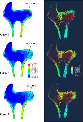
illustrates the predicted stress distribution for the three cases on a single central cross-section through the femur head. However, the observations mentioned below remain valid for any cross-section of the femur head. First of all, significantly different stored elastic energies were obtained. As it can be seen in , these differences are due to notable changes in stress (and strain) fields. To help the comparison, the value of von Mises stress, at the point exhibiting the biggest differences, is indicated in the figure. The value of this stress varies from 14.2 to 27.5 MPa depending on the material model used. Case 1 gives the smallest value, case 2 the largest one. The principle stress directions are less influenced by the constitutive model handled because they are mainly related to applied external load, which is the same for all cases.
Figure 2. Predicted distributions of von Misses stresses and principle directions.
4. Conclusions
Our results show that only correctly defined anisotropic properties of cancellous bone will lead to reliable values of stresses and strains in the bone. In the context of the interpretation of the differences in the results it is worth noting that the seemingly small changes in the stress can lead to significant changes of bone microarchitecture during adaptation process. This conclusion is also supported by the differences found in stored elastic energies.
Additional information
Funding
References
- Abramoff MD, Magalhães PJ, Ram SJ. 2004. Image processing with ImageJ. Biophoton Int. 11(7):36–42.
- Creuillot V, Dreistadt C, Kalinski K, Lipinski P. 2016. Advances in intelligent systems and computing. 414:15–32.
- Doube M, Kłosowski MM, Arganda-Carreras I, Cordelières FP, Dougherty RP, Jackson JS, Schmid B, Hutchinson JR, Shefelbine SJ. 2010. BoneJ: free and extensible bone image analysis in ImageJ. Bone. 47(6):1076–1107.
- Gross T, Pahr DH, Zysset PK. 2013. Morphology–elasticity relationships using decreasing fabric information of human trabecular bone from three major anatomical locations. Biomech Model Mechanobiol. 12(4):793–800.
- Medtool Manual 4.3. [accessed 2019 May 21]. http://www.dr-pahr.at/html/01.html.
- Zadpoor AA, Weinans H. 2015. Patient-specific bone modeling and analysis: the role of integration and automation in clinical adoption. J Biomech. 48(5):750–760.
- Zysset PK, Curnier A. 1995. An alternative model for anisotropic elasticity based on fabric tensors. Mech Mater. 19:240–254.