
 ?Mathematical formulae have been encoded as MathML and are displayed in this HTML version using MathJax in order to improve their display. Uncheck the box to turn MathJax off. This feature requires Javascript. Click on a formula to zoom.
1. Introduction
Fragility fractures of bones are a worldwide health problem. Actual gold standard methods to assess bone fragility have shown to be insufficient (Siris et al. Citation2004; Chapurlat Citation2013). Finite elements models (FEM) have been proposed to evaluate bone strength. Most of the previous studies used a static axial loading to assess bone strength. However, among fractures due to a fall from the standing height, only 15% are related to an axial loading (Melton et al. Citation2010) and the velocity can reach 2 m/s (Tan et al. Citation2006). Thus, we assume that this dynamic loading should be considered.
The main aim of our study is to develop and validate a finite elements model to predict radius bone strain under loading conditions simulating a fall. To reach this goal a first step consisted in developing an ex-vivo protocol to reproduce a forward fall leading to fractured and non-fractured bones (already published) and now comparing experimental surface strains of the distal radius with a specimen-specific finite element model.
2. Methods
2.1. Ex-vivo protocol
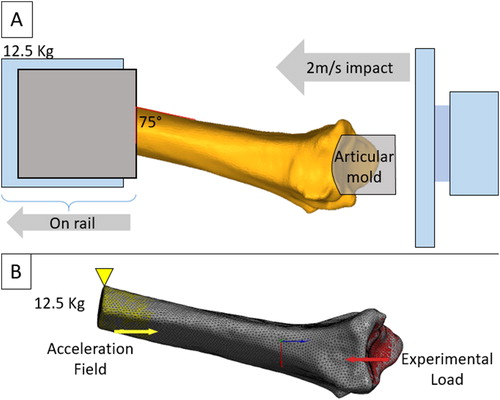
The experimental protocol used here has previously been described in detail (Zapata et al. Citation2017). Briefly, thirty left radii from elderly donors (50–96 y.o. 15 males, 15 females) were tested in a fall configuration. The radius was potted in a polyurethane resin in a steel cylinder, with an angle of 75° between the anterior face of the radius and the impactor. This position reproduces alignment of the radius in the most common forward fall (Chiu and Robinovitch Citation1998). The potted specimens were placed in a horizontal cylinder bar on a rail system which is free to slide along the loading axis. This bar has a weight of 12.5 kg, which is an arbitrary value representing the mass involved in a fall (i.e., a percentage of the body weight). The radii were then loaded through a resin mold at 2 m/s using a hydraulic high speed impact machine (LF technologies, France).
Four high-speed cameras (FASTCAM SA3, Photron, Japan) recorded the impact. Video recordings were analyzed using VIC3D stereo-correlation software (Correlated Solution, South Carolina, USA). Speckled was painted on the specimen in order to compute Von Mises surface strain fields on a specified non fractured zone by means of principal strains.
2.2. Finite element models
Previously acquired cone beam CT (CBCT) scans (New-Tom 5 G, QR, Verona, Italy) with an isotropic resolution of 150 µm were used to create finite elements models. The radii were segmented using the open-source platform 3D Slicer (Slicer.org) resulting in the definition of bone geometry through faceted surfaces. Then, tetrahedral volume meshes were generated using Ansys Software (v. 19.0, Ansys® Inc., USA). According to a preliminary global and local mesh convergence analysis, element size was 0.7 mm resulting to an approximate number of 300 000 elements per model.
Three previously established density–elasticity relationships (Eqs. (Equation1(1)
(1) )–(Equation3
(3)
(3) )) were investigated that allowed for inhomogeneous linearly-isotropic material properties to be assigned to the finite element models (the Young’s modulus
is expressed in MPa, and the densities, respectively ash density, apparent density and hydroxyapatite equivalent density in
).
(1)
(1)
(2)
(2)
(3)
(3)
This resulted in around 220 bins ranging from 0.05 to 11.2 GPa for Eq. (Equation1(1)
(1) ), from 0.03 to 11.5 GPa for Eq. (Equation2
(2)
(2) ) and from 0.01 to 18 GPa for Eq. (Equation3
(3)
(3) ). Each bin was assigned a Poisson’s ration of 0.3.
The models were specifically oriented in the same configuration as the experiments in order to apply the maximal peak load observed experimentally along the z axis uniformly distributed on the articular surface (red surface ). A 12.5 kg distributed mass was applied to the proximal end of the radius at the location of potting and was constrained in the x and y direction and was let free in the z direction (Yellow surface ). Inertia relief was calculated so that the applied forces and torques are balanced by inertial forces induced by an acceleration field. Analyses were performed using Ansys (v. 19.0, Ansys® Inc., USA).
Figure 1. (A) Experimental (from Zapata et al. Citation2017) and (B) Finite Element model configuration.
Surface strain fields (Von Mises strains) were computed in order to compare the bone numerical response with the experimental data analyzed with stereo-correlation.
3. Results and discussion
As a case study, only the results of one specimen will be presented here. Von Mises strain fields computed by stereo-correlation was shown in . The finite element predicted strains varied as a function of Eqs. (Equation1(1)
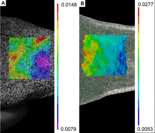
(1) )–(3) in value but not in spatial distribution. Von Mises strains present a similar pattern for the three equations (). Even if simulated and experimental fields are not exactly similar, they presents some common characteristics. The maximal equivalent strains are located on the upper distal region whereas the minimum values are located on the lower proximal region of the radius.
Figure 2. Comparison between experimental (A) and computational (B, Eq. (1)) strain distribution in a non-fracture zone.
Regarding the mean value on the specified zone (), it was found that Eq. (Equation2(2)
(2) ) and (3) underestimate the experimental value whereas Eq. (Equation1
(1)
(1) ) shows more similar results. It is possible that the use of ash density which need to be converted from the hydroxyapatite equivalent density using an additional equation may explain this difference.
Table 1. Mean Von Mises strain for experimental and numerical data on a specified non fractured zone.
But this result agreed with Edwards and Troy (2011) who found best results with this equation on radius strength and strain prediction. Nevertheless, these results should be confirmed on a larger set of radii.
4. Conclusions
This study presents the methodology to assess a subject-specific finite element model in a fall configuration. Further analysis over more oncoming samples will be performed to confirm this result.
Additional information
Funding
References
- Burkhart TA, Andrews DM, Dunning CE. 2013. Finite element modeling mesh quality, energy balance and validation methods: A review with recommendations associated with the modeling of bone tissue. J Biomech. 46(9):1477–1488.
- Chapurlat R. 2013. Contribution and limitations of the FRAX® tool. Joint Bone Spine. 80(4):355–357.
- Chiu J, Robinovitch SN. 1998. Prediction of upper extremity impact forces during falls on the outstretched hand. J Biomech. 31(12):1169–1176.
- Duchemin L, Bousson V, Raossanaly C, Bergot C, Laredo JD, Skalli W, Mitton D. 2008. Prediction of mechanical properties of cortical bone by quantitative computed tomography. Med Eng Phys. 30:321–328.
- Edwards WB, Troy KL. 2012. Finite element prediction of surface strain and fracture strength at the distal radius. Med Eng Phys. 34:290–298.
- Keller TS. 1994. Predicting the compressive mechanical behavior of bone. J Biomech. 27(9):1159–1168.
- Melton LJ, Christen D, Riggs BL, Achenbach SJ, Müller R, van Lenthe GH, Amin S, Atkinson EJ, Khosla S. 2010. Assessing forearm fracture risk in postmenopausal women. Osteoporos Int. 21(7):1161–1169.
- Morgan EF, Bayraktar HH, Keaveny TM. 2003. Trabecular bone modulus-density relationships depend on anatomic site. J Biomech. 36(7):897–904.
- Siris ES, Chen Y-T, Abbott TA, Barrett-Connor E, Miller PD, Wehren LE, Berger ML. 2004. Bone mineral density thresholds for pharmacological intervention to prevent fractures. Arch Intern Med. 164(10):1108–1112.
- Tan J-S, Eng JJ, Robinovitch SN, Warnick B. 2006. Wrist impact velocities are smaller in forward falls than backward falls from standing. J Biomech. 39(10):1804–1811.
- Zapata E, Rongieras F, Pialat J-B, Follet H, Mitton D. 2017. An ex vivo experiment to reproduce a forward fall leading to fractured and non-fractured radii. J Biomech. 63:174–178.