
 ?Mathematical formulae have been encoded as MathML and are displayed in this HTML version using MathJax in order to improve their display. Uncheck the box to turn MathJax off. This feature requires Javascript. Click on a formula to zoom.
1. Introduction
The design and control of walking robots is a great issue for researchers (high number of DOFs, coupled phenomena). They could benefit to the biomechanics community as testing beds for bio-inspired motor control or prosthetics researches. This paper presents the recent retrofitting work of the ROBIOSS team on the large-sized humanoid robot BIP (15 DOFs, 1.8 m, and 105 kg) (Sardain et al. Citation1998). This paper aims to show the feasibility and the efficiency of an industrial controller operating a humanoid robot. We propose here a general overview of the platform evolution, its controller and its hardware. Some results are given to illustrate the relevance of this approach.
2. Methods
2.1. Mechanical retrofit
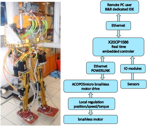
An important effort was done to select the appropriate actuators to replace the old 190 V DC brushless motors. To facilitate the hardware integration, 80 V DC brushless motors were chosen. The method developed to choose the adequate motor was to use reference computed gaits generated for the initial version of the humanoid BIP. The original version being heavier than the new one, the proposed approach is meaningful in terms of actuator sizing. The generated gaits are obtained from the dynamic walking generator given in subsection 3.1. A dynamic model of the robot gives back the motor torques. Several tests were carried out for different gaits (stepping, walking at different speeds with different initial knee flexions, squat and sway motions) and for all the joints. New mechanical brackets were designed to fix the new motors on the existing frame which consist of the yellow anodized parts in . New belt/pulleys ratios were computed to adapt the characteristics of the motors to the joints. All the existing sensors (potentiometers on the joints axis and force sensors in the sole) were tested and calibrated.
Figure 1. ORHRO and its control architecture.
2.2. Control hardware retrofit
The heart of the control hardware () is a B&R X20CP1586 unit PLC (ATOM 1.6 GHz processor with 512 MB DDR2 RAM) that communicates over an Ethernet POWERLINK protocol with the drives and I/O cards. The ACOPOSmicro drives provide a small computation unit to support the adjustable low level control loop and a limited number of functions, notably the feed forward controller.
This set-up was also selected to be scalable. The fieldbus bandwidth allows us to install easily any number of I/O modules. Moreover, any lack of computation power could be palliated by replacing the X20CP1586 unit with an industrial PC without modifying the control software.
2.3. Software architecture
We developed entirely our controller with an Object Oriented Programming approach. We opted for a complete integrated design to avoid any compatibility issue from external libraries and to palliate the lack of specific tools required for humanoid control in the native B&R environment. The embedded controller relies on a new framework for real-time multiaxis and multirobot control called “RTRobMultiAxisControl” (Fischer et al. Citation2019), which facilitates interoperability.
The controller consists in a main synchronous core and several specific modules (structural and utilitarian). The core module manages the synchronous behaviour of the robot and its main task runs a set of functions that could be split into a classical acquisition/processing/action loop. There are three structural modules: Mechanism, Virtual Mechanism and Control.
The two mechanism modules contain a full set of objects allowing a complete representation of the machine such as the Forward Kinematic Model or the Inverse Dynamic Model. The Control module manages every high level control law.
Five utilitarian modules have been implemented so far: a dedicated mathematical and matrix calculation library supporting the matrix-based Lagrangian formalism, a trajectory generator, a signal processing unit, a parametrical identification module designed to calibrate the sensors and an input/output file manager.
3. Results and discussion
3.1. Dynamic motion generator
ORHRO dynamic motion generator is based on Kajita et al. (Citation2003) that models the humanoid as an inverted pendulum with a concentrated mass located at the Center Of Gravity (COG), its altitude being constant. Its advantages are to obtain decoupled equations, on the transversal and longitudinal axis, between COG and Zero Moment Point (ZMP) and also to control the ZMP of the whole robot via its COG.
The Inverse Kinematics Model of the humanoid robot (15 unknowns) is solved as follow. The multibody COG needs to follow the computed path of the inverted pendulum (3 nonlinear equations). 8 nonlinear equations are used to constrain the posture (6 for the position and the orientation of the free foot and 2 for the orientation of the trunk, the yaw motion being relaxed). The last constraints are the range limits of the 15 joints. The classical method used to solve this redundant problem is to minimize at time step a criterion
given in Eq. (1) under constraints using Sequential Quadratic Programming.
(1)
(1)
Where
is the articular coordinate vector at time step
Global parametric optimization will be used in the future to obtain some more human-like motions.
3.2. First experiments
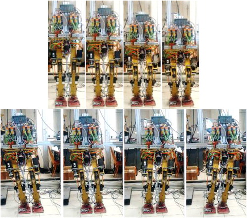
The period of the PLC controller is set at 2 ms. The motions () have been generated offline with the dynamic motion generator stated in 3.1.
Figure 2. Squat and sway motions.
3.2.1. Squat motion
We use here a fifth order polynomial interpolator between starting and ending positions to generate the vertical motion of the COG (range of motion: 15 cm, duration: 5 s). The COG is kept fixed in the transversal plane, the orientation of the trunk is kept vertical.
3.2.2. Sway motion
To avoid torque peaks, the reference path of the ZMP, being located within the support polygon, is built as piecewise polynomial functions of time with null speed and acceleration at the beginning and at the end of each phase. The ZMP motion is only transversal (range of motion: 13 cm, transfer duration: 3.75 s). The orientation of the trunk is kept vertical.
shows the obtained motions: the constraints are respected (orientation of the trunk). This good behaviour emphasizes the ability of the proposed control architecture to execute complex motions. Fatigue tests were carried on to assess the robustness of OHRHO in terms of control and mechanics.
4. Conclusions
This paper presents the evolution from BIP to ORHRO, a humanoid robot with a new control architecture based on a new framework for real-time multiaxis and multirobot control. The preliminary experiments have shown the validity of the proposed approach to achieve dynamic motions.
Additional information
Funding
References
- Fischer H, Vulliez M, Laguillaumie P, Vulliez P, Gazeau J.P. 2019. RTRobMultiAxisControl: a framework for real-time multiaxis and multirobot control. IEEE Trans Automat Sci Eng. 16(3):1205–1217.
- Kajita S, et al. 2003. Biped walking pattern generation by using preview control of zero-moment point. Proc IEEE ICRA2003. 2:1620–1626.
- Sardain P, Rostami M, Bessonnet G. 1998. An anthropomorphic biped robot: dynamic concepts and technological design. IEEE Trans Syst Man Cybern A. 28(6):823–838.