
 ?Mathematical formulae have been encoded as MathML and are displayed in this HTML version using MathJax in order to improve their display. Uncheck the box to turn MathJax off. This feature requires Javascript. Click on a formula to zoom.
1. Introduction
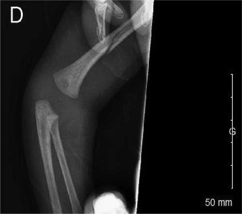
A juridical reporting was realized by the pediatric department about the case of a month-old child hospitalized for fractures of the right upper limb. It was a question of a spiral fracture of the humerus and a metaphyseal pullout of the ulna (). This infant did not have pathologic history, outside a prematurity. In this context of a young infant fracture, who is unable to mobilize himself alone, an abuse was suspected and, from forensic medicine point of view, we had to answer to several specific judge’s questions about the origin of these injuries. His mother made a link between these fractures and a torsion of his arm by putting a pyjama too slim. The questions was: are these fractures compatibles with a classic dressing or a more violent act is it necessary? A biomechanical analysis should enable us to better specify the related injury mechanisms.
Figure 1. X-ray image of the trauma.
From a mechanical point of view, it seems important to determine the direction and magnitude of the applied load to analyse the origin of the fracture. The bone trauma and the injury scenario can be leaded by a superposition of loads, structural asymmetry as well as inappropriate load transfer. For long bones, a transverse fracture, with a fracture line perpendicular to the long axis of the bone, may occur as a result of tensile loading and bending (Pierce et al. Citation2004). In other cases, a moment (due to torsion or bending) may lead to spiral fracture (Pierce et al. Citation2004). The trauma scenario can be addressed by separating the loading conditions and testing each of them independently in order to quantify a range of failure load.
In the present clinical case with observation of a spiral fracture, we investigated the bending and torsional strength of an infant humerus. For that, we proposed two approaches with objective to provide an indicative failure range under these loads, either separately or combined. We addressed the mechanical problem from (i) an analytical approach with a structural analysis and (ii) a numerical study with a simplified finite element (FE) model.
2. Methods
2.1. Analytical approach
To analyse mechanisms and stress levels leading to moment fracture, we firstly performed a structural analysis by approaching the humeral bone as a beam with specific boundary conditions on the extremities. Extremity corresponding to humeral head was fixed and we imposed force and moment on the distal extremity to mimic bending or torsion loadings. Thus, we can identify stress levels involved by bending or torsion in the model:
(1)
(1)
(2)
(2)
where Mb and Mt are respectively the bending moment and the torsion moment, I2 the second moment of area, I0 the polar moment of area and r the radius of the bone.
These both moments were assumed to be involved by a same force imposed at an extremity (corresponding to the hand of the child). The created moments resulted from this force multiplied by a level arm with dimensions measured on X-ray images.
2.2. Numerical approach
To obtain an overview of stress distribution in the segment, we developed a simplified Finite Element (FE) model of the humeral bone. FE analysis was carried out using SolidWorks software (Dassault Systèmes Corporation, Waltham, MA, USA). We approached the model from a cylindrical geometry with evolution of diameter measured on X-ray projection. As for the analytical approach, we imposed boundary conditions to reproduce bending and torsion loadings. The cortical wall was very thin, around 2 mm, and as we wanted to analyse stress distribution, we simulated the model by considering an homogenous cancellous bone material with an elastic modulus of 5 GPa (Kriewall et al. Citation1981).
2.3 Failure evaluation
For bending and torsion, the moment values to failure were determined following maximum principal strain criterion. We considered that the bone failure occurred for stress value corresponding the level when the maximum strain reached the threshold of the elastic strain limit (Altai et al. Citation2018). For human bone these limits have been reported to be 0.73% in tension and 1.04% in compression (Bayraktar et al. Citation2004). For comparison purposes, the equivalent failure moments were also calculated.
3. Results and discussion
From the analytical approach, we found that the maximum stress limit could be reached by a bending moment equal to 10.05 N.m or a torsion moment of 5.02 N.m. These moment values respectively correspond to forces equal to 236 N and 50 N applied on the hand.
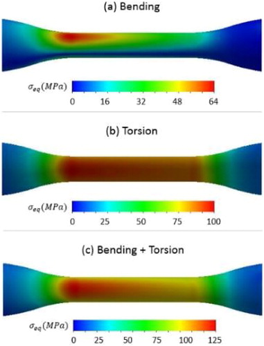
presents some numerical results from the FE analysis with equivalent stress distribution according to different loading conditions. These results were obtained for a same force of 50 N applied on the hand generating a bending loading () and torsion moment equal to 5 N.m (). As previously observed, torsion loading involved higher stress values in the diaphysis part of the bone segment. shows stress distribution for a combination of bending and torsion. This scenario corresponds to the most unfavourable case leading to significant lesion close to metaphysis zone.
Figure 2. Equivalent stress distribution in humerus bone according to bending or torsion loadings for an applied force of 50 N on the hand extremity.
One main limitation of this work was the precise determination of the maximum stress limit. One solution could be to use mechanical data providing bending and torsional strength measured on young bone in growing from animal specimens to validate our FE model (Bertocci et al. Citation2017). The results obtained in the present study can be corroborated with the clinical case of child fracture. The spiral fracture has been certainly caused by a torsion loading or by a combination of bending and torsion. It is important now to determine if this type of mechanism can be caused by movements of dressing/undressing of the infant. In future works, we could characterize these types of movements from a kinematical analysis to obtain real values of motion amplitudes and loadings.
4. Conclusions
In this study, we presented a mechanical analysis of bending and torsion loadings on infant humerus to understand mechanisms able to cause spiral failure. The analytical and numerical approaches revealed that excessive torsion loading could involve fracture in the diaphysis part of the bone as it has been observed during clinical investigation.
References
- Altai Z, Viceconti M, Offiah AC, Li X. 2018. Investigating the mechanical response of paediatric bone under bending and torsion using finite element analysis. Biomech Model Mechanobiol. 17(4):1001–1009.
- Bayraktar HH, Morgan EF, Niebur GL, Morris GE, Wong EK, Keaveny TM. 2004. Comparison of the elastic and yield properties of human femoral trabecular and cortical bone tissue. J Biomech. 37(1):27–35.
- Bertocci G, Thompson A, Pierce MC. 2017. Femur fracture biomechanics and morphology associated with torsional and bending loading conditions in an in vitro immature porcine model. J Forensic Leg Med. 52:5–11.
- Kriewall TJ, McPherson GK, Tsai AC. 1981. Bending properties and ash content of fetal cranial bone. J Biomech. 14(2):73–79.
- Pierce MC, Bertocci GE, Vogeley E, Moreland MS. 2004. Evaluating long bone fractures in children: a biomechanical approach with illustrative cases. Child Abuse Negl. 28(5):505–524.