
 ?Mathematical formulae have been encoded as MathML and are displayed in this HTML version using MathJax in order to improve their display. Uncheck the box to turn MathJax off. This feature requires Javascript. Click on a formula to zoom.
Abstract
Finite element (FE) models can unravel the link between intervertebral disc (IVD) degeneration and its mechanical behaviour. Nucleotomy may provide the data required for model verification. Three human IVDs were scanned with MRI and tested in multiple loading scenarios, prior and post nucleotomy. The resulting data was used to generate, calibrate, and verify the FE models. Nucleotomy increased the experimental range of motion by 26%, a result reproduced by the FE simulation within a 5% error. This work demonstrates the ability of FE models to reproduce the mechanical compliance of human IVDs prior and post nucleotomy.
1. Introduction
The intervertebral disc (IVD) is an essential part of the spine, providing the required flexibility and distributing the loads on the adjacent vertebrae. The kinematic and mechanical functions of the IVD are determined by its histologically and functionally distinct nucleus pulposus (NP), annulus _brosus (AF), and endplate (EP) tissues. In a healthy disc, the highly hydrated NP supports compressive loads while the surrounding AF supports tensile stresses caused by torsion or bending and constrains the lateral expansion of the NP by resisting tensile hoop stresses (White and Panjabi Citation1990).
IVD degeneration is an aberrant, cell-mediated response to progressive structural failure (Adams and Roughley Citation2006). NP and AF show aggrecan degradation, change in collagen type I to type II ratio, decrease in water and glycosaminoglycans (GAG) concentration, reduction in the concentration of viable cells (Johnstone and Bayliss Citation1995; Bibby et al. Citation2001) and increased synthesis of matrix-degrading enzymes (Roughley Citation2004). Eventually, these alterations lead to height loss (Brinckmann Citation1986; Goel et al. Citation1986), load redistribution within the disc (Adams et al. Citation1996) and on the underlying vertebra (Maquer et al. Citation2015). At advanced stages of degeneration, fissures and cracks appear in the disorganized AF (Vernon-Roberts Citation1980), leading to posterior disc bulging and ultimately spinal stenosis (Adams and Roughley Citation2006), which all have been clinically associated with disc herniations or discogenic pain (Brisby Citation2006; Yang et al. Citation2015). From a strictly mechanical point of view, disc degeneration generally increases joint laxity and stiffness (Ellingson et al. Citation2013). Hence, the ability to estimate the mechanical behaviour of an IVD could potentially be linked to its state of degeneration and thus be used as a diagnostic tool for the detection of early degeneration.
In silico models, especially finite element analysis (FEA), are increasingly employed to investigate the effect of such degenerative alterations in both composition and structure of the IVD (Gilbertson et al. Citation1995; Schmidt et al. Citation2013). The latest models were recently used to show the impact of degeneration on the NPs swelling capacity (Yang and O’Connell Citation2019), to determine the bone remodelling mechanisms of the vertebral bodies following a nucleotomy (Calvo-Echenique et al. Citation2019), or to detect early degenerative changes via magnetic resonance imaging (MRI)-based models (Chetoui et al. Citation2019).
Numerical models require experimental data for calibration and validation purposes. Unfortunately, inducing reproducible IVD degeneration on human discs in vitro to generate such data is difficult. On the other hand, nucleotomy, a procedure consisting in the partial or complete removal of the NP, is simple and easy to reproduce. Nucleotomy is a radical procedure that drastically changes the internal structure of the IVD. It was shown to cause disc de-pressurization, EP strain reduction (Broc et al. Citation1997; Frei et al. Citation2001; Heuer et al. Citation2008), increase in the disc’s neutral zone under cyclic compressive loads (Showalter et al. Citation2014), and to affect the deformation patterns of the laminae within the AF (Seroussi et al. Citation1989; Meakin and Hukins Citation2000; Meakin et al. Citation2001). Therefore, nucleotomy constitutes an ideal model to study how the disc’s mechanical behaviour is influenced by structural changes.
To allow the development and implementation of precision, patient-specific, diagnostic tools for detecting early degenerative changes in the IVD, require careful validation of the model’s ability to predict the mechanical response of both the intact and the damaged IVD under a full range of daily spinal loading. This study aims to demonstrate the potential of MRI-based FE models to estimate the behaviour of the intact IVDs under a wide range of applied loading conditions, and its ability to successfully predict the effect of severe damage to its constitute functional tissue, for example, the significant loss of nucleus function introduced via a nucleotomy procedure ().
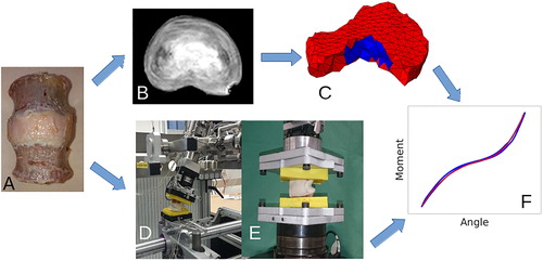
Figure 1. Study overview: Three human lumbar IVDs were prepared (A) and scanned in a clinical 3 T MRI device (B). Using the acquired images, a finite element model was generated. The model is composed of isotropic NP and anisotropic AF elements including to distinct fibre families (C). The IVD joints were embedded in PMMA end-caps, and the mechanical compliance of the disc joints was measured in bending, flexion, extension, rotation (D) and tension (E). The measured load-displacement curves were used to calibrate the material properties of the FE model (F). Finally, a trans-endplate nucleotomy was performed and the testing procedure was repeated.
2. Materials and methods
2.1. Samples
Lumbar vertebral IVD’s are the most affected by disc degeneration (Saleem et al. Citation2013). Therefore, three lumbar, functional spine units were harvested from two fresh frozen cadaveric spines (A: L2-L3 and L4-L5 segments from a female, 32 years, and B: L2-L3 segments from a male, 60 years). With the sample still frozen, the posterior processes were removed and all soft tissues dissected with care not to injure the IVD. To isolate the disc joint, the cranial and caudal vertebral bodies were sectioned transversely at mid-body height. Each specimen was wrapped in saline-soaked gauze and stored in a double plastic bag at −20°C. Freezing can damage the disc tissue and potentially lead to a change in the its mechanical behaviour (Hongo et al. Citation2008). We assumed that such damage, if existing, would impact the IVD’s mechanical behaviour before and after nucleotomy similarly.
2.2. MR imaging
Each IVD was thawed, wrapped in saline soaked gauze for 4 hours at room temperature. The samples were then placed in a custom-made imaging chamber. To decrease susceptibility effects at the surface of the tissue (Benveniste et al. Citation2000) and prevent dehydration, the imaging chamber was filled with Manganese chloride (MnCl2, 10 mM). The chamber was located in a hand/wrist coil (MR2AGD330172, Siemens Healthcare, Germany) with the disc’s cranial-caudal axis aligned with the B0 field of the MRI scanner (Magnetom Prisma fit, 3 T, Siemens Healthcare, Germany). T1-weighted sequences (TR: 14.1 ms, TE: 5 ms) for IVD-background contrast and proton density (PD) weighted sequences (TR: 1700 ms, TE: 5.5 ms) for NP-AF contrast were used to acquire axial images (slice thickness: 0.4 mm, in-plane resolution: 0.285 mm) (). A spine surgeon evaluated the degeneration state of the discs using the Pfirrmann criterion (Pfirrmann et al. Citation2001).
2.3. Mechanical testing
Immediately after MRI imaging, the cranial and caudal vertebral bodies were embedded in polymethyl methacrylate (PMMA) cement (Technovit 3040, Heraeus Kulzer, Hanau, Germany). The bone-PMMA interface stability was further increased by inserting screws into the vertebral bodies before embedding (Wilke et al. Citation2002). A saline-soaked gauze was wrapped around the samples at all times to prevent drying of the sample.
2.3.1. Multi-axial testing
Each embedded disc joint was secured to a custom, computer-controlled, six degrees of freedom (DOF) spine testing system (Gédet et al. Citation2007). The disc was exposed to pure moments (up to 6 Nm, 0.5°/s, displacement controlled) in flexion, extension, and assuming symmetry, right lateral bending and right axial rotation. Thanks to a friction-free air-bearing system, the disc was allowed to freely deform about the remaining five DOF. Each loading scenario was repeated five times. An active optical tracking system (Optotrak Certus, Northern Digital, Canada, accuracy: 0.1 mm) was used to record the resulting six DOF motions of the disc joint while all forces and torques were recorded using a six DOF load cell (MC3A, AMTI, USA, accuracy: 2 N, 0.01 Nm). The error of the measured angles was shown to be below 0.2°.
2.3.2. Tensile testing
Although the application of tensile loading has limited clinical relevance, it imposes uniform tensile loading on the AF fibres, thus providing relevant data to calibrate or validate numerical models. For this purpose, the disc was secured to a hydraulic testing system (858 Mini Bionix II, MTS, Eden Prairie, MN) and five loading cycles (0 N to 270 N, loading rate = 10 N/s) were applied at the geometrical center of the IVD. The test frame was designed to allow the cranial vertebra to freely translate along the disc’s transversal plane with rotational motions constrained. The applied loads and resulting displacements were recorded using the MTS built-in sensors (load cell: model 662.20 D-04 and LVDT displacement sensor).
2.4. Trans-endplate nucleotomy
After testing, a trans-endplate nucleotomy (Johannessen et al. Citation2006; Vresilovic et al. Citation2006) was employed to depressurize and mechanically remove parts of the NP. The centre of the NP with respect to the joint transverse plane was identified on the MRI images, and a 4.5 mm hole was drilled through the EP along the cranial-caudal axis. No further steps to remove NP material other than drilling were performed. This procedure preserved the structural integrity of the AF and ensured exposure of the NP cavity to environmental pressure. However, it did damage the vertebral EP. Once completed, the entire testing procedure was repeated.
2.5. Loading curve analysis
Our focus was on the role of NP and fibre arrangement on the multiaxial mechanical behaviour of the IVD. Therefore, we chose not the include any viscous effects in the present model. Accordingly, the acquired in vitro loading curves had to be post-processed to serve as ground truth for quasi-static models.
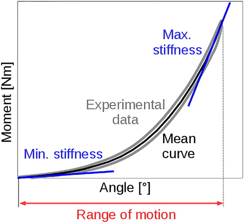
The measured data points (acquisition rate: 100 Hz) were cleaned with a moving average filter (kernel size: 5). The first three loading cycles of each loading scenario were discarded as preconditioning. Cycle four and five were averaged and the mean value of the hysteresis was computed at 20 locations, resulting in an average interval of 0.3° (0.03 mm). For the tensile loading case, the drift caused by the discs poro- and viscoelastic behaviour was subtracted before averaging the cycles. The resulting curves were used to calibrate the material constants. A third-order polynomial was fitted through the points (R2 = 0.98) from which the minimum stiffness (S_min) at 0.1° (0.02 mm) and maximum stiffness (S_max) at the maximum displacement were computed (). The ROM was defined as the displacement at the maximum moment (force).
Figure 2. Definition of the flexibility parameters used to compare the in vitro measurements with the FE predictions.
2.6. Image processing and model generation
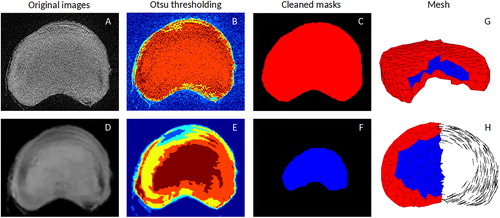
The entire image processing, meshing and material mapping pipeline was developed using Matlab (V.15, Mathworks, USA). First, a multi-threshold Otsu algorithm (Otsu Citation1979) was applied to the T1-weighted MR images () to extract the geometry of the IVD. For each image dataset, six thresholds were computed (). Regions corresponding to background or noise were removed, the others were merged into the IVD mask (). Morphological operations (erode and dilate) were applied to remove the islands, close the holes and smooth the mask. In a second step, the previously generated mask was used to generate quadratic, 10-node tetrahedral elements using the ISOMESH toolbox (Fang and Boas Citation2009). The element size was selected based on our previous study where the effect of mesh density on quality metrics, solution accuracy and CPU time were evaluated (Maquer et al. Citation2015). As all tested meshes were of good quality and within 5% difference for all loading cases (flexion, extension, torsion, bending and compression), the coarsest mesh (3 mm edge length) was used. Next, the segmentation segmentation procedure was repeated for the PD-weighted images () to create the mask of the NP. This time, only the innermost region of the Otsu regions was kept () before applying the morphological operations. Finally, all elements from the IVD mesh whose centroid was in the NP mask were assigned to the NP element set, the others to the AF element set.
Figure 3. The geometry of the IVD was defined from the T1-weighted MR image (A). An multi-region Otsu threshold was first applied (B). The non-connected voxels and holes were then removed with morphological operations to generate the IVD mask (C). The same procedure was applied to the proton density-weighted MR image (D, E) to generate the NP mask (F). The IVD mask was used to create a tetrahedral mesh (G). The elements belonging to the NP mask were assigned the NP material properties, the others were assigned the AF material properties, including a fibre orientation based on the outer shape of the AF (H).
The boundary conditions were defined to replicate experimental test conditions as follows; the caudal and cranial nodes were combined in two kinematic coupled sets corresponding to the vertebral end-plates. The caudal element set was constrained in all directions while the cranial set was assigned the moment/force of the individual loading cases. The cranial set was allowed to move freely along the remaining DOF.
2.7. Constitutive law and material mapping
Inspired by the Holzapfel-Gasser-Odgen model (Holzapfel et al. Citation2000; Eberlein et al. Citation2001), a time-independent hyper-elastic, fibre-reinforced material law was implemented as an Abaqus (6.13 Dassault Systemes, France) user material. The law was described as a free energy function (EquationEquation (1)(1)
(1) ). It incorporates an isotropic term representing the ground substance (EquationEquation (2)
(2)
(2) ), and an anisotropic term with two normalised vectors (a4 and a6 corresponding to the two main collagen fibre directions) representing the fibrous part of the IVD (EquationEquation (3)
(3)
(3) ). The angles of these vectors in the transverse plane of the IVD were defined following the outer shape of the AF. The angle of the vectors with respect to the transverse plane was defined during the material constants optimisation procedure. Elements from the NP element set were assigned isotropic material properties (ψfibres=0). Those from the AF element set were assigned both the isotropic and anisotropic part of the material law.
(1)
(1)
(2)
(2)
(3)
(3)
(4)
(4)
(5)
(5)
(6)
(6)
k1 and k2 correspond to the stiffness and non-linearity of the AF fibres with the invariants I4 and I6 describing the deformations and reorientations of the fibres derived from the deformation gradient F. At the material level, the fibres are only active under tension
= 0 if I4,6 < 1). κ is the resistance against volumetric deformations (bulk modulus), μ the resistance against isochoric deformations (shear modulus). As highlighted by Nolan and colleagues (Nolan et al. Citation2014), the full anisotropic invariants (EquationEquation (6)
(6)
(6) ) were used.
2.8. Identification of the material parameters against the experimental tests
Based on the protocol of Maquer et al. (Maquer et al. Citation2015), a particle swarm optimisation (PSO) (w: 0.7, c1: 1.2, c2: 1.6, nb particles: 25) algorithm (Clerc and Kennedy Citation2002) was used to calibrate the material constants by minimizing the difference between the simulated and experimental data curves. The custom algorithm was implemented in Python (Python v2.7.13, Numpy v1.13).
The outcome of this optimisation provided the numerical values for the NP intact shear modulus (μ_np_i), the NP intact bulk modulus (κ_np_i), the AF shear modulus (μ_af), the AF bulk modulus (κ_af), the fibre stiffness (k1), the fibre non-linearity (k2) and the fiber angle (ϕ). With the assumption that the nucleotomy only affected the elements of the NP, the damaged NP shear modulus μ_np_d and the damaged NP bulk modulus κ_np_d were determined upon secondary optimisation procedure against the in vitro data after nucleotomy where all material constants belonging to the AF were kept from the intact calibration round. In total, 18 hours were required for the complete set of optimisation (Intel i7 quad-core, 3.2 GHz, 32 GB RAM). As previously described for the measurements, a third-order polynomial was fitted through the predicted load-displacement curves and S_min, S_max, and ROM were computed to allow for comparison between in vitro and in silico data.
3 Results
3.1. Comparison intact and denucleated load-displacement data
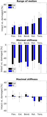
The in vitro load-displacement curves for both intact and denucleated IVDs are presented in . In response to moments of 6 Nm, nucleotomy resulted in an average increase of 20% for flexion, extension and lateral bending, 28% for rotation, and 43% for tension. On average, minimum stiffness decreased by by 52%. Although no consistent direction of change was not observed for the maximal stiffness, it changed on average by 6% under all moment loading modes ().
Figure 4. The FE model replicates the in vitro load-displacement curves. Black and gray represent the experimental data for the intact and damaged case, the dotted lines show the corresponding FE predictions.
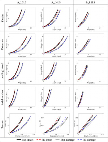
Figure 5. Mean relative difference in ROM, minimal stiffness and maximal stiffness between intact and denucleated samples at 6 Nm (270 N) for all loading cases for the experimental data (black) and FE predictions (blue).
All IVDs were graded according to the Pfirrmann scale (Pfirrmann et al. Citation2001) as grade two. The older sample (B_L2L3) demonstrated decreased ROM and increased initial stiffness in all directions as well as reduced post nucleotomy alterations compared to the younger samples (A_L2L3 and A_L4L5).
3.2. Comparison experimental and simulated load-displacement data
summarizes all in silico load-displacement curves for intact and denucleated IVDs. The average discrepancies of the intact FE model were 4% for the ROM, 31% for the S_min and 14% for S_max compared to the experimental values. For the denucleated FE model, these were 5% for the ROM, 35% for S_min and 13% for S_max against the in vitro data. A detailed table of all computed flexibility parameters is given in (appendix A). summarizes all material constants for the intact and damaged case computed by the PSO calibration.
Table A1. S_max, S_min and ROM at 6 Nm (270 N) for intact and damaged discs, for all loading cases, experimental data and FE predictions.
Table 1. Material constants resulting from the calibration of the models with the in vitro load-displacement data. The index _i stands for intact and _d for the denucleated variables with μ_np the NP shear modulus, κ_np the NP bulk modulus, μ_af the AF shear modulus, κ_af the AF bulk modulus, k1 the fibre stiffness, k2 the fibre non-linearity, and ϕ fibre angle.
3.3. Element size sensitivity
The sensitivity of the FE model to the element size was evaluated for the intact case only. Reducing the element size from 3 mm mean edge length to 2.5 mm resulted in an average increase of 3.7% in predicted ROM, a decrease of 3.5% in S_min, and a decrease of 3.8% in S_max. Increasing the element size to 3.5 mm resulted in a decrease of 5.9% in ROM, an increase of 3.0% in S_min and an increase of 5.2% in S_max ().
Table 2. Element size sensitivity. Native mean edge length is 3 mm, (−) corresponds to 2.5 mm mean edge length and (+) 3.5 mm mean edge length. All values are given in [%] change compared to the native element size.
4. Discussion
A nucleotomy procedure was applied as a simple model to induce clinically relevant structural changes into human IVDs. The goal of the study was to develop a subject-specific IVD FE model with the ability mimic the alterations of the IVD’s overall mechanical behaviour. For this purpose, the multi-axial compliance of three human IVDs was measured prior and post nucleotomy in the laboratory. The material constants of the model were calibrated against the in vitro data and the model’s ability the reproduce the measured load-displacement curves was evaluated.
In vitro nucleotomy resulted in an ROM increase of average increase in ROM of 26% at 6 Nm (270 N). The minimal stiffness was reduced by 52% while the maximal stiffness did not follow a clear trend, but changed on average by 6%. These findings are following previous studies that observed a clear trend of increased ROM and a reduction in initial stiffness post nucleotomy. Applying a nucleotomy on a L4-L5 IVD, Wilke et al. reported at 7.5 Nm an average increase in ROM of 18% for flexion/extension, 12% for lateral bending and 21% for axial rotation (Wilke et al. Citation2002). The lower values by the Wilke study can be explained with the fact that, unlike our study, the facet joints were left in place. While successively reducing the anatomy of spinal segments, Heuer and colleagues found that the nucleotomy increased the ROM (at 5 Nm) by 37% for flexion, 49% for extension, 38% for bending and 47% for rotation (Heuer et al. Citation2008). Lafage et al. (Citation2007) reported an increase in ROM (at 8 Nm) after nucleotomy of 15% for flexion and extension, 39% for lateral bending and 50% for axial rotation. While the nucletomy procedure was only performed on one disc, the testing procedure was applied to two complete motion segments, making direct comparisons more difficult. It’s also important to note that the nucleotomies in these studies were conducted via an incision through the AF, which might have further changed the mechanical response of the IVD (Johnstone and Bayliss Citation1995).
The fibre angles yielded by the optimisation procedure (25.2° to 32°) were in agreement with anatomical observations (Eberlein et al. Citation2004; Iatridis and Ap Gwynn Citation2004; Holzapfel et al. Citation2005; Pezowicz Citation2010). However, previous studies further found that the angle of the fibres varies from 23° in the anterior part to 45° in the posterior part and that the type of fibres and their associated stiffness change from the outer to the inner AF (Holzapfel et al. Citation2005). Although we did not account for these regional variations of the fibrous network, the FE model successfully reproduced the moment-deformation response curves measured experimentally for the intact and denucleated IVD. Our model estimated the measured ROM with an average error below 5%, S_min was estimated with an error of 33% and S_max with an error 14%. We suggest that the larger error in estimation for S_min was mainly caused by the low absolute values.
A sensitivity analysis revealed that altering the mean element edge length by ± 20% resulted on average in less than 5% change of the flexibility parameters (ROM, S_min and S_max). These findings are in agreement with our previous study (Maquer et al. Citation2015). These variations have two causes beyond the simple effect of mesh density for isotropic homogeneous materials. First, because of the homogenisation, the coarser the mesh, the “rougher” the in-plane fibre distribution. Second, the IVD was meshed as a single part and only later assigned NP or AF material constants. While this method allows for a simple, automatic and regular mesh generation, a change in element size can lead to a slightly different ratio between NP and AF volume (± 2%) and different geometry. We have employed this method for the sake of limiting the computing time associated with our optimisation strategy. A more robust method would be to apply a direct MRI-based material mapping as we previously suggested (Stadelmann et al. Citation2018). Still, based on the sensitivity tests, these variations were minimal.
Beyond the common constraints associated with the use of cadaver material in vitro, this study is limited by the fact that our FE model was not designed to simulate any time-dependent behaviour, which is present in the IVD (Humzah and Soames Citation1988; Keller et al. Citation1987). The focus of this feasibility study was to develop a model that can accurately estimate a multi-axial quasi-static response.
Our assumption of a fully reversible elastic behaviour is supported by a previous study demonstrating the sensitivity of angular motion to loading rate to be relatively low (Wilke et al. Citation1998). In our study, the hystereses of the acquired angular load-displacement curves accounted on average for 10.5% of the stored elastic energy and was found not to drift between the cycles. For the tensile loading scenario, we measured a small drift that was subtracted from the data to allow a comparison with a quasi-static model. Such a correction would not have been possible for the highly rate-dependent axial compression (Race et al. Citation2000). To avoid misinterpretations, no measurements and no simulations were performed in axial compression.
Even with the low number of samples, the experimental data revealed the large intra-specimen variability (up to 45% difference in ROM). These variations are most probably caused by differences in both the geometry (Maquer et al. Citation2014) and composition of the individual IVDs. While the geometry can be captured very well using clinical MRI scanners, the in vivo quantification of the IVD composition and fibre architecture remain a major challenge. For the present study, a specific set of material constants was calibrated for each IVD, limiting its use for potential clinical applications. Our findings call therefore for improved MR imaging to quantify collagen fibre density/orientation and proteoglycan content in order to directly assign IVD-specific material properties (Stadelmann et al. Citation2018). In the future, it might be possible to augment in vivo low resolution clinical MR images with a-priori information extracted from ex vivo high resolution images using machine learning techniques as it is already done with bone tissue and CT images (Chandran et al. Citation2017, Citation2019).
In conclusion, this study demonstrated that a rate-independent FE model of the IVD is able to reproduce up to five distinct load cases with a fair accuracy before and after nucleotomy. Nucleotomy is an extreme case of structural damage. FEA has therefore the potential to cope with any degenerative alterations of the disc structure, especially if combined with quantitative MR imaging.
Disclosure statement
The authors have no conflict of interest to declare.
Additional information
Funding
References
- Adams MA, Roughley PJ. 2006. What is intervertebral disc degeneration, and what causes it? Spine. 31(18):2151–2161.
- Adams MA, McMillan DW, Green TP, Dolan P. 1996. Sustained loading generates stress concentrations in lumbar intervertebral discs. Spine. 21(4):434–438.
- Benveniste H, Kim K, Zhang L, Johnson GA. 2000. Magnetic resonance microscopy of the C57BL mouse brain. Neuroimage. 11(6 Pt 1):601–611.
- Bibby SR, Jones DA, Lee RB, Yu J, Urban JP. 2001. The pathophysiology of the intervertebral disc. Joint Bone Spine. 68(6):537–542.
- Brinckmann P. 1986. Injury of the annulus fibrosus and disc protrusions. An in vitro investigation on human lumbar discs. Spine. 11(2):149–153.
- Brisby H. 2006. Pathology and possible mechanisms of nervous system response to disc degeneration. J Bone Joint Surg Am. 88(Suppl 2):68–71.
- Broc GG, Crawford NR, Sonntag VKH, Dickman CA. 1997. Biomechanical effects of transthoracic microdiscectomy. Spine. 22(6):605–612.
- Calvo-Echenique A, Bashkuev M, Reitmaier S, Pérez-del Palomar A, Schmidt H. 2019. Numerical simulations of bone remodelling and formation following nucleotomy. J Biomech. 88:138–147.
- Chandran V, Maquer G, Gerig T, Zysset P, Reyes M. 2019. Supervised learning for bone shape and cortical thickness estimation from CT images for finite element analysis. Med Image Anal. 52:42–55. [30471462]
- Chandran V, Reyes M, Zysset P. 2017. A novel registration-based methodology for prediction of trabecular bone fabric from clinical QCT: a comprehensive analysis. PLoS One. 12(11):e0187874. DOI 10. 1371/journal.pone.0187874
- Chetoui MA, Boiron O, Ghiss M, Dogui A, Deplano V. 2019. Assessment of intervertebral disc degeneration-related properties using finite element models based on [formula: see text]-weighted MRI data. Biomech Model Mechanobiol. 18(1):17–28.
- Clerc M, Kennedy J. 2002. The particle swarm-explosion, stability, and convergence in a multidimensional complex space. IEEE Trans Evol Comput. 6(1):58–73.
- Eberlein R, Holzapfel GA, Fröhlich M. 2004. Multi-segment FEA of the human lumbar spine including the heterogeneity of the annulus fibrosus. Comput Mech. 34(2):147–163.
- Eberlein R, Holzapfel GA, Schulze-Bauer CAJ. 2001. An anisotropic model for annulus tissue and enhanced finite element analyses of intact lumbar disc bodies. Comput Methods Biomech Biomed Eng. 4(3):209–229.
- Ellingson AM, Mehta H, Polly DW, Ellermann J, Nuckley DJ. 2013. Disc degeneration assessed by quantitative T2* (T2 Star) correlated with functional lumbar mechanics. Spine. 38(24):E1533–E1540.
- Fang Q, Boas DA. 2009. Tetrahedral mesh generation from volumetric binary and grayscale images. Proceedings - 2009 IEEE International Symposium on Biomedical Imaging: From Nano to Macro, p. 1142–1145. Boston, Massachusetts: IEEE
- Frei H, Oxland TR, Rathonyi GC, Nolte LP. 2001. The effect of nucleotomy on lumbar spine mechanics in compression and shear loading. Spine. 26(19):2080–2089.
- Gédet P, Thistlethwaite PA, Ferguson SJ. 2007. Minimizing errors during in vitro testing of multisegmental spine specimens: considerations for component selection and kinematic measurement. J Biomech. 40(8):1881–1885.
- Gilbertson LG, Goel VK, Kong WZ, Clausen JD. 1995. Finite element methods in spine biomechanics research. Crit Rev Biomed Eng. 23(5-6):411–473. v23.i5-6.20
- Goel VK, Nishiyama K, Weinstein JN, Liu YK. 1986. Mechanical properties of lumbar spinal motion segments as affected by partial disc removal. Spine. 11(10):1008–1012.
- Heuer F, Schmidt H, Wilke HJ. 2008. Stepwise reduction of functional spinal structures increase disc bulge and surface strains. J Biomech. 41(9):1953–1960. 2008.03.023
- Holzapfel GA, Gasser TC, Ogden RW. 2000. A new constitutive framework for arterial wall mechanics and a comparative study of material models. J Elast. 61(1/3):1–48. DOI 10.1023/A:1010835316564.
- Holzapfel GA, Schulze-Bauer CAJ, Feigl G, Regitnig P. 2005. Single lamellar mechanics of the human lumbar anulus fibrosus. Biomech Model Mechanobiol. 3(3):125–140.
- Hongo M, Gay RE, Hsu JT, Zhao KD, Ilharreborde B, Berglund LJ, An KN. 2008. Effect of multiple freeze-thaw cycles on intervertebral dynamic motion characteristics in the porcine lumbar spine. J Biomech. 41(4):916–920.
- Humzah MD, Soames RW. 1988. Human intervertebral disc: structure and function. The Anatomical Record. 220(4):337–356. DOI 10.1002/ar.1092200402
- Iatridis JC, Ap Gwynn I. 2004. Mechanisms for mechanical damage in the intervertebral disc annulus fibrosus. J Biomech. 37(8):1165–1175.
- Johannessen W, Cloyd JM, O'Connell GD, Vresilovic EJ, Elliott DM. 2006. Trans-endplate nucleotomy increases deformation and creep response in axial loading. Ann Biomed Eng. 34(4):687–696.
- Johnstone B, Bayliss MT. 1995. The large proteoglycans of the human intervertebral disc. Changes in their biosynthesis and structure with age, topography, and pathology. Spine. 20(6):674–684.
- Keller TS, Spengler DM, Hansson TH. 1987. Mechanical behavior of the human lumbar spine. I. Creep analysis during static compressive loading. J Orthop Res. 5(4):467–478.
- Lafage V, Gangnet N, Sénégas J, Lavaste F, Skalli W. 2007. New interspinous implant evaluation using an in vitro biomechanical study combined with a finite-element analysis. Spine. 32(16):1706–1713.
- Maquer G, Laurent M, Brandejsky V, Pretterklieber ML, Zysset PK. 2014. Finite element based nonlinear normalization of human lumbar intervertebral disc stiffness to account for its morphology. J Biomech Eng. 136(6):061–003.
- Maquer G, Schwiedrzik J, Huber G, Morlock MM, Zysset PK. 2015. Compressive strength of elderly vertebrae is reduced by disc degeneration and additional flexion. J Mech Behav Biomed Mater. 42(325230):54–66.
- Meakin JR, Hukins DWL. 2000. Effect of removing the nucleus pulposus on the deformation of the annulus fibrosus during compression of the intervertebral disc. J Biomech. 33(5):575–580.
- Meakin JR, Redpath TW, Hukins DWL. 2001. The effect of partial removal of the nucleus pulposus from the intervertebral disc on the response of the human annulus fibrosus to compression. Clin Biomech. 16(2):121–128.
- Nolan DR, Gower AL, Destrade M, Ogden RW, McGarry JP. 2014. A robust anisotropic hyperelastic formulation for the modelling of soft tissue. J Mech Behav Biomed Mater. 39:48–60.
- Otsu N. 1979. A threshold selection method from gray-level histograms. IEEE Trans Syst Man Cybern. 9(1):62–66.
- Pezowicz C. 2010. Analysis of selected mechanical properties of intervertebral disc annulus fibrosus in macro and microscopic scale. J Theor Appl Mech. 48(1954):917–932.
- Pfirrmann CWA, Metzdorf A, Zanetti M, Hodler J, Boos N. 2001. Magnetic resonance classification of lumbar intervertebral disc degeneration. Spine. 26(17):1873–1878.
- Race A, Broom ND, Robertson P. 2000. Effect of loading rate and hydratation on the mechanical properties of the disc. Spine. 25(6):662–669.
- Roughley PJ. 2004. Biology of intervertebral disc aging and degeneration: involvement of the extracellular matrix. Spine. 29(23):2691–2699. DOI 10.1097/01.brs.0000146101.53784.b1
- Saleem S, Aslam HM, Rehmani MAK, Raees A, Alvi AA, Ashraf J. 2013. Lumbar disc degenerative disease: disc degeneration symptoms and magnetic resonance image findings. Asian Spine J. 7(4):322–334.
- Schmidt H, Galbusera F, Rohlmann A, Shirazi-Adl A. 2013. What have we learned from finite element model studies of lumbar intervertebral discs in the past four decades? J Biomech. 46(14):2342–2355.
- Seroussi RE, Krag MH, Muller DL, Pope MH. 1989. Internal deformations of intact and denucleated human lumbar discs subjected to compression, flexion, and extension loads. J Orthop Res. 7(1):122–131.
- Showalter BL, Malhotra NR, Vresilovic EJ, Elliott DM. 2014. Nucleotomy reduces the effects of cyclic compressive loading with unloaded recovery on human intervertebral discs. J Biomech. 47(11):2633–2640.
- Stadelmann MA, Maquer G, Voumard B, Grant A, Hackney DB, Vermathen P, Alkalay RN, Zysset PK. 2018. Integrating MRI-based geometry, composition and fiber architecture in a finite element model of the human intervertebral disc. J Mech Behav Biomed Mater. 85:37–42.
- Vernon-Roberts B. 1980. The pathology and interrelation of intervertebral disc lesions, osteoarthrosis of the apophyseal joints, lumbar spondylosis and low back pain. The lumbar spine and backpain. 2nd ed. Tunbridge: Pitman Medical Publishing.
- Vresilovic EJ, Johannessen W, Elliott DM. 2006. Disc mechanics with trans-endplate partial nucleotomy are not fully restored following cyclic compressive loading and unloaded recovery. J Biomech Eng. 128(6):823–829.
- White M, Panjabi A. 1990. Clinical biomechanics of the spine. 2nd ed., vol. 2. Philadelphia: Lippincott, p. 18–20.
- Wilke HJ, Jungkunz B, Wenger K, Claes LE. 1998. Spinal segment range of motion as a function of in vitro test conditions: Effects of exposure period, accumulated cycles, angular- deformation rate, and moisture condition. Anat Rec. 251(1):15–19. 251:1⟨15::AID-AR4⟩3.0.CO;2-D
- Wilke HJ, Kavanagh S, Neller S, Claes L. 2002. Effect of artificial disk nucleus implant on mobility and intervertebral disk high of an L4/5 segment after nucleotomy. Orthopade. 31(5):434–440.
- Yang B, O’Connell GD. 2019. Intervertebral disc swelling maintains strain homeostasis throughout the annulus fibrosus: a finite element analysis of healthy and degenerated discs. Acta Biomater. 100:61–74.
- Yang H, Liu H, Li Z, Zhang K, Wang J, Wang H, Zheng Z. 2015. Low back pain associated with lumbar disc herniation: role of moderately degenerative disc and annulus fibrous tears. Int J Clin Exp Med. 8(2):1634–1644.
Appendix A
Appendix B
Acronyms
| AF | = | annulus fibrosus |
| DOF | = | degrees of freedom |
| EP | = | endplate |
| FEA | = | finite element analysis |
| ϕ | = | fibre angle |
| IVD | = | intervertebral disc |
| k1 | = | fibre stiffness |
| k2 | = | fibre non-linearity |
| κ_af | = | AF bulk modulus |
| κ_np_d | = | NP damaged bulk modulus |
| κ_np_i | = | NP intact bulk modulus |
| μ_af | = | AF shear modulus |
| μ_np_d | = | NP damaged shear modulus |
| μ_np_i | = | NP intact shear modulus |
| NP | = | nucleus pulposus |
| PD | = | proton density |
| PMMA | = | polymethyl methacrylate |
| PSO | = | particle swarm optimisation |
| S_max | = | maximum stiffness |
| S_min | = | minimum stiffness |
| TE | = | echo time |
| TR | = | repetition time |