
 ?Mathematical formulae have been encoded as MathML and are displayed in this HTML version using MathJax in order to improve their display. Uncheck the box to turn MathJax off. This feature requires Javascript. Click on a formula to zoom.
1. Introduction
Estimation of the kinematics of the natural or prosthetic knee joint from skin markers is challenging due to soft tissue artefact (Camomilla et al. Citation2017). A solution can be to perform a multibody kinematics optimisation but the model-derived kinematics is very sensitive to the kinematic constraints. Subject-specific kinematic constraints based on contact point trajectories (obtained by a series of static biplane X-rays on healthy subjects) have been recently implemented in a musculoskeletal model (Zeighami et al. Citation2018). Such constraints based on fluoroscopic data have never been obtained nor assessed yet.
The objective of this study is to evaluate subject-specific kinematic constraints obtained by fluoroscopy on patients with a total knee prosthesis.
2. Methods
2.1. Experimental data
Skin marker data from the Grand Challenge Competition to Predict in vivo Knee Loads (Fregly et al. Citation2012) are analysed to evaluate the knee prosthesis kinematics and slip velocities during level walking.
For one patient (JW), the contact point trajectories derive from a contact model driven by fluoroscopy-based kinematics (i.e., monoplane measurements at foot strike and foot-off of treadmill gait) (Zhao et al. Citation2007). For the three other patients (DM, SC, and PS), the contact point trajectories are directly measured by biplane fluoroscopy during lunge (Varadarajan et al. Citation2008). The four contact point trajectories (i.e., on medial and lateral condyles and plateaus) are interpolated by third-order polynomial functions of the knee flexion to be applied to any other motion task.
2.2. Multibody kinematics optimisation
Joint kinematics during gait is estimated by multibody kinematics optimisation, formulated as:
The lower limb model is parameterised with natural coordinates Qi (i.e., i = 1, 2, 3, 4 for foot, shank, thigh, and pelvis, respectively) (Dumas and Chèze Citation2007). Objective function f, driving constraints kinematic constraints
and rigid body constraints
are detailed in Duprey et al. (Citation2010). Explicitly, the kinematic constraints stand for a universal joint at the ankle, the superimposition of the medial and lateral contact points of tibia and femur at the knee, and a spherical joint at the hip. The positions of the contact points embedded in the shank and thigh segments are prescribed as a function of the knee flexion angle θ. These positions are obtained in the inertial coordinate system using an interpolation matrix (Dumas and Chèze Citation2007) as, for example, for the jth virtual marker (here a contact point) of the ith segment:
Therefore, the kinematic constraints, set equal to zero, for the medial contact point (i.e., 1rst virtual marker in shank and thigh segments) are
Interestingly, the slip velocity s at medial contact and, similarly, the slip velocity at lateral contact is directly obtained by differentiating this relation (i.e., with and
depending on the knee flexion angle θ):
3. Results and discussion
3.1. Prosthesis kinematics
Subject-specific knee kinematics demonstrates high inter-subject variability, typically in internal-external rotation and anterior-posterior displacement (). Patient SC presents an exaggerated internal rotation. Nevertheless, the prostheses generally exhibit internal rotation and anterior displacement (of small amplitudes) coupled with flexion.
Figure 1. Estimated knee prosthesis kinematics.
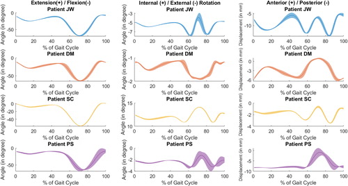
This seems consistent with the prosthesis design (i.e., standard congruent tibial insert and posterior cruciate-retaining femoral component) whose motion attempts to mimic the natural knee kinematics.
3.2. Contact velocities
For all patients, the mean slip velocities at medial and lateral contacts are similar and present four peaks, the two mains occurring at pre-swing and terminal swing (). Patient JW has a different prosthesis design and shows higher velocities (i.e., up to 220 mm/s). These slip velocity profiles reveal a rolling and pivoting motion with slipping in both compartments.
Figure 2. Estimated slip velocities.
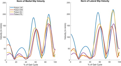
In the literature, for comparable posterior cruciate-retaining prostheses, medial and lateral slip velocities were reported reaching 300 mm/s during stance and 500 mm/s during swing (Andriacchi et al. Citation2003). These slip velocities were estimated from skin markers without any kinematic constraints but with adjustments to ensure contact between the CT-scan models of the patients. The resulting prosthesis kinematics were similar to . Using an equivalent natural knee kinematics and geometrical considerations (i.e., radius of curvature), medial and lateral maximal slip velocities during stance were estimated at 82 mm/s and 45 mm/s, respectively (Nerkowski Citation1997). In the present study, it is possible that the interpolation of the contact point trajectories by polynomial functions results in smoothed slip velocities. Moreover, for three patients, these trajectories are obtained during lunge and may be somewhat different during gait.
4. Conclusions
Subject-specific kinematic constraints based on contact point trajectories obtained by fluoroscopy have the potential to estimate representative knee joint kinematics and contact velocity which are important for patient diagnosis and follow-up, as well as for prosthesis design and evaluation.
Acknowledgements
The authors thank B. J. Fregly from Rice University for providing fluoroscopic and numerical row data for patient JW and thank C. Marais from Université de Lyon for his help in processing all data. This work was partially funded by LABEX PRIMES (ANR-11-LABX-0063) of Université de Lyon.
References
- Andriacchi TP, Dyrby CO, Johnson TS. 2003. The use of functional analysis in evaluating knee kinematics. Clin Orthop Relat Res. 410:44–53.
- Camomilla V, Dumas R, Cappozzo A. 2017. Human movement analysis: the soft tissue artefact issue. J Biomech. 62:1–4.
- Dumas R, Chèze L. 2007. 3D inverse dynamics in non-orthonormal segment coordinate system. Med Biol Eng Comput. 45(3):315–322.
- Duprey S, Cheze L, Dumas R. 2010. Influence of joint constraints on lower limb kinematics estimation from skin markers using global optimization. J Biomech. 43(14):2858–2862.
- Fregly BJ, Besier TF, Lloyd DG, Delp SL, Banks SA, Pandy MG, D'Lima DD. 2012. Grand challenge competition to predict in vivo knee loads. J Orthop Res. 30(4):503–513.
- Nerkowski E. 1997. Relation entre cinématique tridimensionnelle du genou, géométrie et structure ligamentaire. RBM-News. 19(3):94–101.
- Varadarajan KM, Moynihan AL, D'Lima D, Colwell CW, Li G. 2008. In vivo contact kinematics and contact forces of the knee after total knee arthroplasty during dynamic weight-bearing activities. J Biomech. 41(10):2159–2168.
- Zeighami A, Aissaoui R, Dumas R. 2018. Knee medial and lateral contact forces in a musculoskeletal model with subject-specific contact point trajectories. J Biomech. 69:138–145.
- Zhao D, Banks SA, D'Lima DD, Colwell CW, Jr, Fregly BJ. 2007. In vivo medial and lateral tibial loads during dynamic and high flexion activities. J Orthop Res. 25(5):593–602.