
 ?Mathematical formulae have been encoded as MathML and are displayed in this HTML version using MathJax in order to improve their display. Uncheck the box to turn MathJax off. This feature requires Javascript. Click on a formula to zoom.
ABSTRACT
Long-span timber-concrete composite (TCC) floor systems have the potential to address the design challenges for conventional wooden floors in residential multi-storey timber frame buildings. The aim of this paper is to develop a design approach for long-span timber-concrete composite floor system of 6–9 m. A framework based on value-driven design approach has been developed for integration of results from graphical multi-objective optimisation, spreadsheet-based analysis, structural static and dynamic finite element analysis, and multi-criteria decision making. To verify the developed framework, a residential five-storey timber frame building as a case study has been studied. Optimal design includes optimised thickness of the concrete and optimised smeared stiffness of connectors for three different comfort classes A to C in descending order. TCC floor with span length 7.3 [m] belonging to comfort class A and TCC floor with span length 9.0 [m] belonging to comfort class C has been chosen as optimal solutions. The results indicate that proposed and innovative design approach is a promising tool for developers, architects and structural engineers when designing optimal long-span timber-concrete composite floor system.
Introduction
The trend in multi-storey residential timber frame buildings is open floor plan solutions for modular flexibility, which demands long-spans. Due to low bending stiffness of conventional wooden floor structures, it is not possible to fulfil performance criteria for long-span floor systems, regarding deformations, springiness and vibration (Moroder et al. Citation2014). According to a survey by Jarnerö (Citation2014) ‘the residents in residential multi-storey wooden buildings with conventional wooden floor with normal span length are already annoyed by vibrations in an extent that it should not be neglected’. Jarnerö (Citation2014) concludes ‘the present deflection criterion, i.e. maximum 1.5 [mm/kN] deflection due to point load, is far too generous and needs to be revised even for normal span length’. Jarnerö (Citation2014) suggests further investigations to upgrade the vibration performance criteria in order to achieve improved dynamic properties of the wooden floors in residential multi-storey timber buildings. Toratti and Talja (Citation2006) proposed classification of floors into five categories, A, B, C (as base class), D and E with corresponding criteria. The proposed criteria are tougher, with higher limiting values, than those proposed by Jarnerö (Citation2014). Suggested limiting values for maximum deflection due to 1 kN point load according to Toratti and Talja (Citation2006) for class A, B, C, D and E are 0.12 (0.14), 0.25 (0.33), 0.5 (0.71), 1.0 and above 1.0 [mm] (with limiting values according to Jarnerö (Citation2014) in brackets).
The problems faced in traditional light timber frame floors suffering from excessive deflection, susceptibility to vibrations, and insufficient acoustic separation can be resolved by using timber-concrete composite (TCC) floors (Yeoh et al. Citation2011). The aforementioned problems are connected to the floor span, i.e. a longer span presents more challenges. The definition of long-span floor differs between authors, BFR (Citation1984) proposes 6–8 m as a limit, while span lengths that vary between 8 and 10 m can be considered as long-span according to Khorsandnia, Valipour, and Bradford (Citation2018). TCC floor systems have the potential to address the design challenges for conventional wooden floors in residential multi-storey timber frame buildings. Application of TCC floor systems is emerging as an efficient floor system in tall and multi-storey wooden buildings subjected to high horizontal forces as they offer advantages in terms of both static and dynamic structural performances and structural lateral load capacity. In order to enhance both acoustic and vibration performances it is necessary to have four-sides simply supported boundary conditions for the TCC floor systems.
The materials in TCC floor systems are effectively utilised in terms of strength performance. The timber web is mainly subjected to tension and bending, while the concrete flange is mainly subjected to compression, and the connection system is subjected to shear. Connection system should be both economical and efficient so that the production cost can be reduced (binti Arpaee, Yeoh, and Boon Citation2013). Compared with floor solutions made solely by wood, TCC floor systems offer several advantages, such as (1) increased bending stiffness, mass and damping resulting in lower vertical deflections and improved dynamic response, specially to footfall induced vibrations; (2) increased acoustic performances; (3) increased fire resistance (4) reduced heating and cooling costs due to increased thermal mass (Ceccotti Citation2002; Gutkowski et al. Citation2008; Yeoh et al. Citation2011, Citation2013; Gerber Citation2016) and (5) up to 50% reduction in slab depths resulting in economical usage of height of the building. Besides, in relation to floors with concrete and steel structures, TCC floor systems are lighter, which results in savings in the overall construction (Monteiro et al. Citation2016). Furthermore, TCC floors can match the concrete slab at about half of the weight and half of the embodied carbon.
Indicating the connection efficiency between the structural parts, the TCC structure can be denoted to have NCA, PCA or FCA, referring to no, partial or full composite action, and most TCC connection systems will show PCA.
A stiff and strong connection system is crucial in order to achieve a suitable bending stiffness of the TCC floor system. Hence, a minimum relative slip between the bottom fibre of the concrete slab and the top fibre of the timber beam, i.e. a high composite efficiency, is a requirement. There are different types of fasteners that can be used as connection system to assure shear force transfer between concrete and timber, e.g. nails, screws, anchor bolts or steel dowels. In one type of TCC floor system for off-site construction, the concrete slab is supported by glulam beams which have mechanical fasteners as connectors with the concrete slab. Glulam beams supported TCC floor systems offer several advantages compared to the traditional timber floor system in terms of structural performances i.e. stiffness and load-bearing capacity, vibrational behaviour and fire and acoustic insulation (Naud et al. Citation2019).
TCC floor systems are increasingly used in new constructions (Yeoh Citation2010). The effort from the industry is to produce TCC floor systems of 6–9 [m], thus long-span floors. Maximum limit of 9 [m] spanning floor allows for open plan office spaces and parking arrangement between supporting columns demanded by commercial buildings. The serviceability limit state is often the governing design factor for TCC floors (Tannert et al. Citation2016). Another benefit could be the possibility for ensuring the competitiveness with pure concrete slabs regarding concrete thickness and thereby less material usage for sustainable design. But there are cost functions and constraints driven from serviceability, stability and sustainability criteria that make the design procedure of TCC floors complicated. Hence, there is a need for developing a procedure for long-span TCC floor systems. Thus, the aim of this paper is to develop a value-driven design (VDD) approach for simply supported, single-span TCC floor system of 6–9 [m] by enhancing both the bending stiffness and dynamic response of the floor and reducing its climate impact. The VDD approach provides a holistic view of the design process and enables all important quantitative and qualitative aspects to be considered with a view to the effect on design of system (Andersson Citation1999).
Serviceability performance in terms of deflection, springiness and vibration (Yeoh et al. Citation2008), as well as sustainability performance in terms of climate impact, production cost and human comfort (Movaffaghi and Yitmen Citation2018) have been identified as the most important design aspects for multi-storey timber buildings. To achieve a well-engineered TCC floor design a framework based on a VDD approach, as a whole system thinking, has been developed in this paper. Whole system thinking reveals and exploits connections between parts and is a way of addressing complex problems and designs involving several different types of processes. Innovative materials and components are the key topics covered by different aspects and scales of system thinking (Habert and Schlueter Citation2016). Achieving a sustainable outcome/design is an open system’s problem within all practical levels in built environment (Godfrey Citation2010).
The structure of this paper is as follows: Literature about VDD approach, vibration performance criteria, multi-objective optimisation (MOO) and multi-criteria decision making (MCDM) have been reviewed. A developed framework for designing TCC floor based on VDD approach has been established. A case study for verifying the developed framework has been analysed with the remark that MCDM has not been included in the analysis for considering both climate impact and costs. Results are presented and discussed, and some important conclusions are drawn.
Theoretical background
Value-driven design approach
VDD approach proposed in the literature (Castagne, Curran, and Collopy Citation2009) aims to complement the traditional design process by using the concept of value for early design generation and selection. VDD approach has been introduced and explained in aircraft development with focus on developing ever faster, better and cheaper aircraft (Isaksson et al. Citation2013). VDD approach as the design’s top-level objective uses flexibility in design process by having several design classes based on different demand limits, optimisation and MCDM. The goal of the VDD approach in this paper is to improve the design by optimising serviceability and sustainability performances of the TCC floor system.
TCC floor system subjected to footfall induced vibration
Floor structures have often been treated as either low- or high-frequency floors where suggestions of 7, 8 or 10 Hz as fundamental frequencies are commonly found in the literature for the frequency of transition. Lightweight (timber/wood) structures with span length below approximately 6–8 m and heavy (concrete) floors ‘with short span’ are related to the high-frequency, while the low-frequency floor includes heavyweight floors with longer span (BFR Citation1984).
Humans are most sensitive to the frequencies between 4 and 8 [Hz], which corresponds to the eigenfrequencies of some of the organs of the human body (Pavic and Reynolds Citation2002a, Citation2002b). A potential risk of resonance is also recognised when the eigenfrequency of the floor structure coincides with the frequency of footfall. Thus, a lower limiting frequency of 8 Hz has been recognised by Eurocode 5 as the lower limit of the first eigenfrequency for timber floors to humanly induced vibrations.
As can be seen in Equation (1), the natural undamped eigenfrequency of the single-span supported floor can be described as a function of the span length l and the square-root of the ratio of bending stiffness EI to mass m. Since the concrete section of a TCC floor contributes to the stiffness as well as to the mass, while the span length is a fixed parameter, a control of the eigenfrequency of the floor must be performed, to ensure that the effect of the gain in bending stiffness is not prevailed by the increase in mass. As it can be seen in Equation (1) the reduction of length has much more impact than reduction of mass.(1)
(1) Short-span TCC floor systems with span length of 4–6 m has normally acceptable dynamic responses to footfall induced vibration since short-span floors often have sufficient transversal bending stiffness with natural eigenfrequency above 8 [Hz]. However, with the floors span length above 6 m, the floors natural eigenfrequency may not meet the requirements above 8 [Hz] (Jarnerö Citation2014).
By footfall induced vibration, the response of the floor system can be split into impulsive or forced due to the heel strike force and resonant or free part of vibration response (Willford and Young Citation2006). The Root Mean Square (RMS) acceleration is the most common way for presentation of the response and widely used where the time is included. The RMS acceleration is defined as:(2)
(2) where T is the period under consideration, a(t) is the acceleration function and t is the time.
Vibration serviceability of TCC floors is developing progressively relevant due to their increased long-span applications (Weckendorf et al. Citation2016). Appropriate vibration performance of the TCC floor system depends on the parameters such as total mass of the floor system, longitudinal and transversal bending stiffness, damping of the floor system (Jarnerö Citation2014) and the shear stiffness of the connectors between timber and concrete. Changing size of each of these five parameters will affect the dynamic response of the TCC floor systems.
Multi-objective optimisation
All design problems are in reality multi-objective due to their nature. The usage of optimisation in product development is growing as both computational capabilities and new developed numerical algorithms are increasing. At the same time, all design problems have more than one conflicting objective in design optimisation and these objectives need to be integrated to yield one final design. Thus, the design problem can be formulated as multi-objective optimisation (MOO) problem (Andersson Citation2000). In MOO, there does not exist only one feasible solution that minimises/maximises all objective functions simultaneously. Instead, attention is paid to Pareto optimal solutions, i.e. solutions that cannot be improved in any of the objectives without degrading at least one of the other objectives. A MOO problem can be managed depending on when the decision-maker articulates his or her preference on the different objectives (Andersson Citation2000). In this paper two different and independent effective bending stiffness of the floor system have been chosen as two objective functions linked to the cost and demand function of the TCC floor system. Optimal design variables include optimised thickness of the concrete and optimised smeared stiffness of connectors.
Multi-criteria decision making
MCDM deals with decisions involving the choice of a best alternative from several potential candidates in a decision, subject to several criteria or objectives. (Cecconi et al. Citation2017). Analytical Network Process (ANP) as a MCDM method proposed by Saaty (Citation2001), admits complex interrelationships among decision levels and attributes. MCDM can also be applied to select some optimal design solutions from pareto optimal fronts in a MOO analysis satisfying some subjective preferences of the stakeholders. Movaffaghi and Yitmen (Citation2018) developed a framework of a multi-objective and multi-criteria based approach for integration of life cycle analysis and dynamic analysis in industrialised multi-storey timber construction.
Theoretical framework based on value-driven design approach
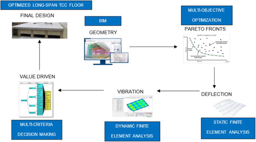
In this paper a theoretical framework based on VDD approach in designing the optimal TCC floor has been developed. The framework integrates serviceability and sustainability performances of the TCC floor based on VDD approach that consists of spread-sheet analysis, structural static and dynamic analyses, finite element analysis (FEA), MOO and MCDM. The flowchart of the framework is presented in .
Figure 1. Flowchart of the developed framework based on VDD approach for optimised long-span TCC floor system.
Building information modelling (BIM) facilitates communication and transparency among stakeholders and design teamwork in order to save time and energy, reduce costs and waste and minimise errors. Thus, the geometry of the TCC floor system has been modelled using a BIM-based software in order to improve project performance and quality for upcoming analysis.
Tannert, Ebadi, and Gerber (Citation2019) showed that calculations according to the γ-method predict capacity, stiffness and dynamic properties within a reasonable degree of accuracy. γ-method according to Annex B of the Eurocode 5 has been used in this study as a simplified design method to predict TCC structural response. Moreover, serviceability criteria in Eurocode 5 has been utilised for verifying TCC floors static and dynamic responses. The expression for static mid-span deflection of a two-way floor system caused by a unit load of 1 [kN] is shown in Equation (3). wherein is the effective bending stiffness of the floor system. Transverse load distribution is taken into consideration through the factor
according to Boverket (Citation1991) as seen in Equation (4). The load distribution takes the stiffness of the materials and the geometry of the cross-section and the floor into consideration, through the function
.
(3)
(3)
(4)
(4) In the studied cases the load distribution function will vary between 0.400 (9 m span, NCA, hc > 80 mm) and 0.432 (6 m span, FCA, hc = 50 mm).
As the demand function the required effective bending stiffness of the TCC floor system for three different comfort classes A to C in descending order has been chosen as the demand function, see Equation (5).
(5)
(5) The effective bending stiffness
of a composite beam based on the γ-method according to Equation (6) has been chosen as the cost function.
(6)
(6) where subscripts c and t refer to concrete and timber elements, respectively; E is the Young’s modulus of the material; A and I are the area and the second moment of area of the element cross-section; a is the distance from the centroid of the element to the neutral axis of the composite section; and γ is the shear connection reduction factor according to Equation (7).
(7)
(7) where s is the spacing of the connectors assumed as smeared along the span of the floor beam; l is the span of the TCC floor beam; and
is the slip modulus of the connector.
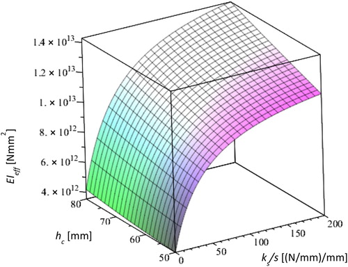
The effective bending stiffness expressed in Equations (5) and (6) have been combined with equal weighting in a MOO. The surface in shows the effective bending stiffness of the TCC floor system as a function of the two design variables: concrete thickness hc and smeared connector stiffness ks/s.
Figure 2. The size of effective bending stiffness of the floor based on the γ-method in terms of concrete thickness hc and smeared stiffness ks/s as two design variables.
By applying the deflection criteria for the different vibration classes given in Toratti and Talja (Citation2006), the minimum bending stiffness fulfilling the point-load criteria can be solved. For simplicity, the load distribution factor was set to 0.4 when determining the required bending stiffness for each class.
Case study
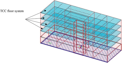
To try out the developed framework, a residential five-storey timber building has been used as a case study. It includes reinforced concrete in the first storey and shaft and light-frame walls with the overall dimension . The building was proposed by the industry and the actual building was built with short-span floors. The interest of the industry is to study if savings can be made by modifying the structure to a long-span floor structure, although these studies are not presented here. The studied structure of the building is presented in .
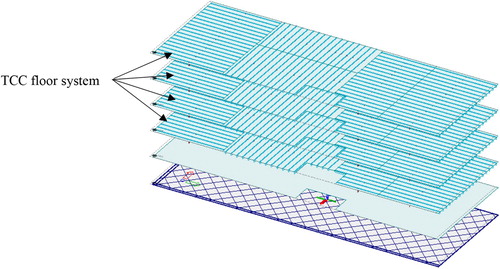
Figure 3. 3D view of the building investigated in the case study with the TCC floor system.
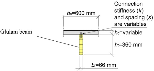
The TCC floor system consists of glulam beams and reinforced concrete slab, joined by shear connectors. All TCC floors are simply supported by both outer walls and apartment separating walls. Cross-section of the investigated TCC floor system is shown in .
Figure 4. Cross-section of the investigated TCC floor system.
The TCC floor with longest span (7.3 [m]) above second to fifth storey has been chosen for further analysis. Besides, span length 9.0 [m] has been analysed as target length in this paper. A 3D view of all floors including TCC floors above second to fifth storey is shown in . The model was defined in the FE program FEM-Design, (Strusoft Citation2019).
Figure 5. 3D view of all floors including TCC floors above second to fifth storey.
The complete TCC floor model contains 102,574 nodes and in total has 615,444 degrees of freedom. The elements consist of second order rectangular 8-nodes shell-elements and second order 3-nodes beam-elements representing concrete floors and glulam beams. The FE-based software automatically merges two parts resulting FCA when the parts share the same positions in the global coordinate system. This is because of displacement continuity between parts that means shared nodes get the same degree of freedoms. Thus, width of the glulam beams in the FE model has been calibrated for capturing PCA. For this reason, the effective bending stiffness of TCC floor for PCA according to γ method in Euro code 5 has been calculated separately and the corresponding with of the glulam beams for the calculated effective bending stiffness of TCC floor for PCA has been used in the FE model. Convergence study on mesh density has been performed. The FE model of the analysed floor with surface load, including self-weight and 10% of imposed load totally 2.4 [kN/m2] can be seen in . The location of excitation points from footfall loading and boundary conditions are also presented. The dynamic response was generated only for a complete TCC floor system with longest span, L = 7.3 m in the structure.
Figure 6. Surface loads 2.4 [kN/m2], simply four-side supported boundary conditions and location of four excitation points 1.1, 2.1, 3.1 and 4.1 on the TCC floor.
![Figure 6. Surface loads 2.4 [kN/m2], simply four-side supported boundary conditions and location of four excitation points 1.1, 2.1, 3.1 and 4.1 on the TCC floor.](/cms/asset/8634ee96-c987-47b3-a68b-692789c5354a/gcee_a_1808888_f0006_oc.jpg)
Results and analysis
The analysed floor is located above second to fifth storey in the residential five-storey timber building in the case study. The results include calculations regarding serviceability and sustainability of the four side simply supported TCC floor with dimensions .
shows required calculated with Equation (5) for the two beam lengths, 7.3 and 9.0 [m] and for three comfort classes A, B and C (Toratti and Talja Citation2006).
Table 1. Required  for floor spans, 7.3 and 9.0 m, to fulfil comfort class A, B and C.
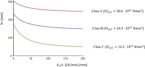
Pareto fronts for three different comfort classes have been picked out from in terms of concrete thickness hc and smeared stiffness ks/s as two design variables and beam lengths 7.3 and 9.0 [m] and can be seen in and . The thickness of the concrete slab was chosen between 50 and 320 [mm] in increments of 5 [mm]. The range of smeared bending stiffness was chosen between 20 and 200
that represent distance of 90 and 9 [mm] between connectors. It must be mentioned that the minimum distance between steel connectors are 20 mm.
Figure 7 . Pareto fronts for comfort class A, B and C in terms of concrete thickness hc and smeared stiffness ks/s as design variables and beam length 7.3 m.
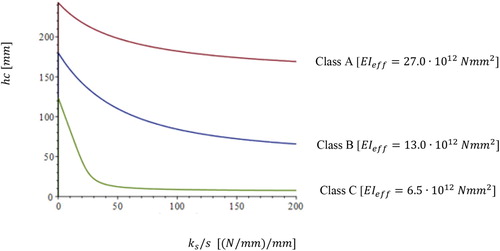
Figure 8. Pareto fronts for comfort class A, B and C in terms of concrete thickness hc and smeared stiffness ks/s as design variables and beam length 9.0 m.
MCDM has taken into account considering only climate impact for selecting one pair of design solution from each of the pareto fronts for three comfort classes A, B and C satisfying some subjective preferences of the stakeholders. It has been assumed that design solution with lowest climate impact gets the highest score from stakeholders. Thus, the design with the lowest concrete thickness has been chosen from each of the pareto fronts as it can be seen besides total mass m in . This was followed by spreadsheet-based analysis according to Eurocode 5 specifications, structural static and dynamic FEA for each of these six design solutions, and finally, MCDM has been performed to choose the optimal design solution from these three classes for both span length 7.3 and 9.0 [m].
Table 2. Selected design solutions , from optimal pareto fronts for three comfort classes A, B and C for two beam length, 7.3 and 9.0 [m].
Static analysis
Static analysis includes calculation for maximum deflection both after short- and long-term loading by means of spreadsheet-based analysis according to Eurocode 5 specifications for floors in comfort class A, B and C as it can be seen in . Maximum deflection for both short- and long-term loading are below the maximum acceptable deflection according to Eurocode 5 for the TCC floor with length 7.3 [m]. It can also be seen in –5 that the span length can be increased from 7.3 to 9.0 [m], still fulfilling requirements for maximum acceptable deflections.
Table 3. Maximum and acceptable deflection for floor belonging to comfort class A for span length 7.3 [m] with hc = 170 [mm] and ks/s = 200 [N/mm/mm] and span length 9 [m] with hc = 245 [mm] and ks/s = 200 [N/mm/mm].
Table 4. Maximum and acceptable deflection for floor belonging to comfort class B for span length 7.3 [m] with hc = 65 [mm] and ks/s = 200 [N/mm/mm] and span length 9.0 [m] with hc = 150 [mm] and ks/s = 200 [N/mm/mm].
Table 5. Maximum and acceptable deflection for floor belonging to comfort class C for span length 7.3 [m] with hc = 50 [mm] and ks/s=20 [N/mm/mm] and span length 9.0 [m] with hc = 50 [mm] and ks/s=200 [N/mm/mm].
Analysis of point load deflection
The calculations for vibration have been performed both by means of spreadsheet-based analysis according to Eurocode 5 specifications and structural static and dynamic finite element (FE) simulations in Fem-Design. Frequency components, vibration magnitude, and damping are the most important parameters affecting human response to floor vibrations (Hu, Chui, and Onysko Citation2001). Vibration performance was evaluated in terms of the deflection caused by (1) 1 kN point load at the most flexible point (2) natural frequencies and corresponding mode shapes of vibration, and (3) footfall induced vibrations.
shows the maximum deflection at the most flexible point caused by 1 [kN] point load for floor belonging to comfort class A, B and C and two span length 7.3 and 9 [m]. The connection between concrete slab and glulam beam can only be assumed rigid (FCA) in the FE software used. For the beam length 7.3 [m] the width has been reduced from 66 [mm] to 53, 55 and 29 [mm] for TCC floor belonging to comfort class A, B and C in the FE model. For the beam length 9.0 m the width has been reduced from 66 [mm] to 56, 57 and 58 [mm] for TCC floor belonging to comfort class A, B and C in the FE model.
Table 6. Maximum deflection caused by 1 [kN] point load at the middle of TCC floor belonging to comfort class A, B and C and beam length 7.3 and 9.0 [m].
The differences in results for the point load deflection between calculated static FEA and spreadsheet-based analysis may arise from the size of transverse load distribution factor used in Equation 4 by spreadsheet-based analysis.
Fundamental natural frequency analysis
Equation 8 below shows the equation for the fundamental natural frequency of the TCC beam (Ohlsson Citation1984), where l is the length of the beam and bc=0.6 [m] is the distance between the beams.(8)
(8) The fundamental natural frequency of the TCC floor system has been calculated both by FEA and spread-based analysis for floor belonging to comfort class A, B and C with beam length 7.3 and 9.0 [m] and presented in .
Table 7. Fundamental natural frequency of TCC floor calculated by both FEA and spreadsheet-based analysis for floor belonging to comfort class A, B and C and beam length 7.3 and 9.0 [m].
Fundamental natural frequency of the TCC floor system belonging to comfort class A, B and C for span length 7.3 [m] calculated by both methods have good agreements and are above the minimum requirement 8 [Hz]. On the other hand, the natural frequencies for all three comfort classes A, B and C for the beam length 9.0 [m] are below 8 [Hz] calculated by both methods, thus, not acceptable. The small differences in results for the first natural frequencies between calculated FEA and spreadsheet-based analysis may arise both from the size of transverse load distribution factor kappa used in Equation 4 by spreadsheet-based analysis and mass differences between FEA and spreadsheet-based analysis due to calibration of the FE model.
The results from parameter study shows that it is possible to fulfil the minimum requirements for the first fundamental natural frequency of the TCC floor with the beam length 9 m belonging to comfort class C by reducing the concrete thickness from 50 mm to 35 mm as can be seen in .
Table 8. Fundamental natural frequency of TCC floor calculated spreadsheet-based analysis for floor belonging to comfort class C and beam length 9.0 [m].
Footfall impact analysis
Vertical RMS acceleration (Strusoft Citation2019) has been calculated in FEM-Design software due to footfall induced excitation at four selected points on the TCC floor, as it can be seen in above. Value for damping was 5% and walkers’ mass was 76 [kg]. Walkers speed was considered in the analysis by limiting the frequency of the footsteps in the range 1.8–2.2 [Hz]. The results are shown in . As can be seen in floor with span length 7.3 m belonging to class A fulfils the tentative acceptable RMS acceleration (Toratti and Talja Citation2006). This floor also fulfils the other requirements regarding deflection, point load deflection, minimum fundamental frequencies in , and .
Table 9. Maximum vertical RMS acceleration [m/s2] at four selected excitation points on the TCC floor calculated by FEA for comfort class A, B and C and beam length 7.3 [m].
Discussion and concluding remarks
Eurocode 5 procedure utilises a simplification for modelling of composite action known as γ-method. The method manipulates the properties of the concrete layer to predict the cross-section characteristics of the structure. This paper outlines a design tool for long-span TCC floor systems based on VDD approach. The aim is to present a design approach for floor long-span TCC floors, and for the tool/approach to be useful in practice it necessitates it to be simple, thus the use of simplified equations. The design tool adequately addresses the complexity of long-span TCC floor systems, including the partial composite action provided by the connectors with focus on both serviceability and sustainability performances. The main purpose of VDD approach in designing the long-span TCC floor system in this paper is better material utilisation in design, and thereby less climate impact. A key element for sustainable design is the structural optimisation as it has been shown in this paper. Optimal design includes optimised thickness of the concrete and optimised smeared stiffness of connectors as TCC floor systems components.
TCC floor with span length 7.3 [m] belonging to class A has been chosen as optimal solution. This floor fulfils all the tentative requirements according to Toratti and Talja (Citation2006) regarding maximum deflection after short and long term, point load deflection at most flexible point on the floor, fundamental natural frequency and vertical RMS acceleration in , 6 and 7 and 8. It must be mentioned that steel connectors climate impact has been assumed to be small in comparison with the climate impact of concrete floor when the production and material transport of the concrete are the main sources for CO2 emissions. Thereby multi-criteria decision making has not been performed in this study. Generally long-span TCC floor results in larger vertical deformations and poor vibration behaviour of the floor (Toratti and Kevarinmäki Citation2001) as the results in this study shows that TCC floor with span length 9 m can only fulfil the lowest comfort class C.
Recommendations for future studies
It will be interesting to compare the results for this floor with experimental results in the future study for calibrating and verification of both FE model and spread-sheet based model. In addition, structural performance in terms of the load-bearing capacity for horizontal forces deteriorates when the number of load-bearing walls that can have stabilising function as shear walls decreases in frames with free TCC floor solutions. In this paper stability performance has not been considered where open plan surfaces increase the wind pressure on supporting shear walls. Stability performance against horizontal forces need to be included in the framework for a comprehensive design solution as recommendations for further study. The possibility to enhance the floor performance and getting more realistic distances between connectors above 20 mm by increasing the height of glulam timber beams will be studied in the next paper.
Acknowledgements
This study is part of the research project ‘Livscykelperspektivet i samhällsbyggande: digitaliserat beslutsstöd för klimatförbättringar’. The authors would like to thank Smart Built Environment for their financial support of the study. Authors would also like to thank Hedareds Sand & Betong AB a manufacturer of the TCC and GIS (Gunnar Ivarsons Stiftelse för Hållbart Samhällsbyggande) in Sweden for supporting the project.
Disclosure statement
No potential conflict of interest was reported by the author(s).
Additional information
Funding
References
- Andersson, J. 1999. “On Engineering System Design. A Simulation Optimization Approach.” Licentiate Thesis., Department of Mechanical Engineering, Linköping University.
- Andersson, J. 2000. A Survey of Multi-Objective Optimization in Engineering Design. Technical Report: LiTH-IKP-R-1097. Linköping, Sweden: Department of Mechanical Engineering Linköping University.
- BFR. 1984. Svikt, svängningar och styvhet hos bjälklag – dimensioneringsregler Rapport. T20: ISBN 91-540-4301-8, Sweden (in Swedish).
- binti Arpaee, M., D. Yeoh, and K. H. Boon. 2012. Timber-Concrete Composite: An Innovative Lightweight Floor Solution. Batu: Universiti Tun Hussein Onn Malaysia.
- Boverket. 1991. SVIKT – Exempel på godtagbar beräkningsmetod. Technical Report (in Swedish) in association with S. Ohlsson. Boverket, Byggavdelningen 1991-07-01. Karlskrona, Sweden (in Swedish).
- Castagne, S., R. Curran, and P. Collopy. 2009. “Implementation of Value-Driven Optimisation for the Design of Aircraft Fuselage Panels.” International Journal of Production Economics 117: 381–388. doi: 10.1016/j.ijpe.2008.12.005
- Cecconi, F. R., L. C. Tagliabue, S. Maltese, and M. Zuccaro. 2017. “A Multi-criteria Framework for Decision Process in Retrofit Optioneering Through Interactive Data Flow.” Procedia Engineering 180: 859–869. doi: 10.1016/j.proeng.2017.04.247
- Ceccotti, A. 2002. “Composite Concrete-Timber Structures.” Progress in Structural Engineering and Materials 4 (3): 264–275. doi: 10.1002/pse.126
- Gerber, A. R. 2016. Timber-concrete Composite Connectors in Flat-plate Engineered Wood Products. PhD thesis. University of British Columbia, Vancouver.
- Godfrey, P. 2010. “Using Systems Thinking to Learn to Deliver Sustainable Built Environments.” Civil Engineering and Environmental Systems 27 (3): 219–230. doi: 10.1080/10286608.2010.482656
- Gutkowski, R., K. Brown, A. Shigidi, and J. Natterer. 2008. “Laboratory Tests of Composite Wood–concrete Beams.” Construction and Building Materials 22 (6): 1059–1066. doi: 10.1016/j.conbuildmat.2007.03.013
- Habert, G., and A. Schlueter, eds. 2016. “Expanding Boundaries: Systems Thinking in the Built Environment.” Sustainable Built Environment (SBE) Regional Conference, Zurich, 2016. vdf Hochschulverlag AG.
- Hu, L. J., Y. H. Chui, and D. M. Onysko. 2001. “Vibration Serviceability of Timber Floors in Residential Construction.” Progress in Structural Engineering and Materials 3 (3): 228–237. doi: 10.1002/pse.69
- Isaksson, O., M. Kossmann, M. Bertoni, H. Eres, A. Monceaux, A. Bertoni, S. Wiseall, and X. Zhang. 2013. “Value-Driven Design–A Methodology to Link Expectations to Technical Requirements in the Extended Enterprise.” Paper presented at INCOSE International Symposium 23(1): 803–819.
- Jarnerö, K. 2014. “Vibrations in Timber Floors- Dynamic Properties and Human Perception.” PhD diss., Linnaeus University.
- Khorsandnia, N., H. Valipour, and M. Bradford. 2018. “Deconstructable Timber-Concrete Composite Beams with Panelised Slabs: Finite Element Analysis.” Construction and Building Materials 163: 798–811. doi: 10.1016/j.conbuildmat.2017.12.169
- Monteiro, S. R. S., A. M. P. G. Dias, and S. M. R. Lopes. 2015. “Bi-dimensional Numerical Modeling of Timber-concrete Slab-type Structures.” Materials and Structures 48 (10): 3391–3406. doi: 10.1617/s11527-014-0407-3
- Moroder, D., T. Smith, M. Simonetti, F. C. Ponzo, A. D. Cesare, D. Nigro, S. Pampanin, and A. H. Buchanan. 2014. “Experimental Behaviour of Diaphragms in Post-tensioned Timber Frame Buildings.” European Conference on Earthquake Engineering and Seismology, Istanbul, Turkey.
- Movaffaghi, H., and I. Yitmen. 2019. “Developing a Framework of a Multi-Objective and Multi-criteria Based Approach for Integration of LCA-LCC and Dynamic Analysis in Industrialized Multi-storey Timber Construction.” In Advances in Informatics and Computing in Civil and Construction Engineering, 447–454. Cham: Springer.
- Naud, N., L. Sorelli, A. Salenikovich, and S. Cuerrier-Auclair. 2019. “Fostering GLULAM-UHPFRC Composite Structures for Multi-Storey Buildings.” Engineering Structures 188: 406–417. doi: 10.1016/j.engstruct.2019.02.049
- Ohlsson, S. 1984. Svikt, svängningar och styvhet hos bjälklag – dimensioneringsmetoder (in Swedish).
- Pavic, A., and P. Reynolds. 2002a. “Vibration Serviceability of Long-Span Concrete Building Floors. Part 1: Review of Background Information.” The Shock and Vibration Digest 34 (3): 191–211.
- Pavic, A., and P. Reynolds. 2002b. “Vibration Serviceability of Long-Span Concrete Building Floors. Part 2: Review of Mathematical Modelling Approaches.” The Shock and Vibration Digest 34 (4): 279–297.
- Saaty, T. L. 2001. “Decision Making with the Analytic Network Process (ANP) and its Super Decisions Software. The National Missile Defense (NMD) Example.” ISAHP 2001 Proceedings, 2–4.
- Strusoft, A. B. 2019. FEM-Design: Theory Manual for Footfall Analysis, Version 1.1.
- Tannert, T., M. M. Ebadi, and A. Gerber. 2019. “Serviceability Performance of Timber Concrete Composite Floors.” Proceedings of the 2019 Modular and Offsite Construction (MOC) Summit Banff, University of Alberta, May 21–24, 2019, Canada.
- Tannert, T., B. Endacott, M. Brunner, and T. Vallée. 2016. “Long-Term Performance of Adhesively Bonded Timber-Concrete-Composites.” International Journal of Adhesion and Adhesives 72: 51–61. doi: 10.1016/j.ijadhadh.2016.10.005
- Toratti, T., and A. Kevarinmäki. 2001. “Development of Wood-Concrete Composite Floors.” IABSE Symposium Report. International Association for Bridge and Structural Engineering, Zurich, Switzerland, vol. 85 (2): 25–30.
- Toratti, T., and A. Talja. 2006. “Classification of Human Induced Floor Vibrations.” Building Acoustics 13 (3): 211–221. doi: 10.1260/135101006778605370
- Weckendorf, J., T. Toratti, I. Smith, and T. Tannert. 2016. “Vibration Serviceability Performance of Timber Floors.” European Journal of Wood and Wood Products 74 (3): 353–367. doi: 10.1007/s00107-015-0976-z
- Willford, M. R., and P. Young. 2006. A Design Guide for Footfall Induced Vibration of Structures. London: Concrete Society.
- Yeoh, D. E. C. 2010. “Behaviour and Design of Timber-concrete Composite Floor System.” PhD thesis, University of Canterbury, Christchurch.
- Yeoh, D., M. Fragiacomo, A. Buchanan, K. Crews, J. Haskell, and B. Deam. 2008. “Development of Semi-prefabricated Timberconcrete Composite Floors in Australasia.” Proceeding of 10th World Conference on Timber Engineering, Miyazaki, Japan.
- Yeoh, D., M. Fragiacomo, and D. Carradine. 2013. “Fatigue Behaviour of Timber–Concrete Composite Connections and Floor Beams.” Engineering Structures 56: 2240–2248. doi: 10.1016/j.engstruct.2013.08.042
- Yeoh, D., M. Fragiacomo, M. De Franceschi, and K. Heng Boon. 2011. “State of the Art on Timber-Concrete Composite Structures: Literature Review.” Journal of Structural Engineering 137 (10): 1085–1095. doi: 10.1061/(ASCE)ST.1943-541X.0000353