
ABSTRACT
This study applies the philosophy of technological mediation to understand how vision-based systems used for civil structure condition assessment transform input of images from cameras into output of structural response. The objective of this study is to understand the mediating role that a vision-based system plays between their users and properties of civil structures that are unperceivable in a great part by humans. A case study of a specific application of such a system is conceived as a responsive digital material with substrates (image frames consisting of millions of pixels) and traces (modelled time-histories to be interpreted by their users). Built-in technological selectivities determine possible differences between modelled time-histories and existing civil structures in reality and attribute to epistemic uncertainties. Modelled time-histories amplify a person’s experience of a certain aspect of the monitored civil structure while simultaneously reducing experiences of other aspects of the structure. Therefore, to prevent human blindness, engineers have to judge outputs of condition assessment systems in the light of specific pre-theoretical shared agreements and routines. Understanding the complex interplay between technological selectivities and different types of human blindness may increase understanding of how these systems can be used successfully in civil structure condition assessment.
1. Introduction
Vision-based systems are becoming prevalent in structural health monitoring (SHM) of civil structures, especially bridges. With speedy developments in camera systems and computational advances, these technologies draw much interest in the SHM community. Vision-based systems provide detailed information about properties of civil structures that would be largely imperceptible to the human eye. These systems receive ‘input’ in the form of images from cameras. These images are transformed into visible ‘output’ representing displacements on a very detailed level. In this way, it is possible to avoid errors for which visual inspection may be susceptible. Nevertheless, this output still requires filtering and interpretation to support decision-makers (e.g. bridge engineers and asset owners). Misunderstandings about the interpretation of this output can lead to poor decision-making (Nielsen et al. Citation2019). With the growing influence of vision-based systems, understanding the ways in which these systems receive inputs and transforms them into outputs and their interpretation becomes therefore increasingly relevant.
The ways in which technology transforms inputs into outputs and interpretation of these outputs are also the focus of the postphenomenological approach of technological mediation (Ihde Citation2009). Ihde, one of the founding fathers of this approach, extensively investigated practices of image use and its interpretation (Ihde Citation1986; Ihde Citation1998; Ihde Citation2009; Rosenberger Citation2011). From the postphenomenological perspective, vision-based systems as imaging technologies can be understood as mediators between their users and the objects monitored (Ihde Citation1990; Rosenberger and Verbeek Citation2015; Verbeek Citation2005). In this view, such a technology comes between its user and a civil structure monitored, and transforms the way a user perceives this object.
The objective of this study is to understand the mediating role that a vision-based system plays between their users and properties of civil structures that is unperceivable in a great part by humans. Two postphenomenological concepts are used to provide deeper insights into the ways how vision-based systems influence or transform users’ perception of a civil structure. The first concept is human intentionality, a core concept in philosophical tradition of the phenomenology. Human intentionality means that human consciousness is always directed towards a certain object in the world: humans do not just think but think about something; they do not just look but look at something (Aagaard Citation2017). This intentionality or directedness may result in different types of human ‘blindness’. The second postphenomenological concept is technological selectivity. The built-in selectivity of a technology is the specific way in which a specific technology is programmed to be directed at a specific aspect of reality (Verbeek Citation2008, 393). Discussing different types of human blindness and technological selectivities provide insights into the main aspects of the technological mediation approach.
A case study of a specific application of a vision-based SHM system supports the philosophical reflection on technological mediation. Detailed information is provided about the process of how ‘input’ in the form of images from cameras is transformed into visible ‘output’ representing bridge displacements. Technological mediation makes certain properties of bridges accessible to humans through data processing. Users turn to vision-based systems in order to read and interpret the representations of structural response time-histories they provide (Rosenberger and Verbeek Citation2015). The scientific contribution of this study is in connecting the operation of vision-based SHM systems to this technological mediation perspective. This is the first study that applies this perspective to the field of vision-based SHM to increase the understanding of the mediating role vision-based systems play in SHM practice.
In this study, we first elaborate on the technological mediation perspective. Next, SHM technologies, hardware for vision measurement, data techniques and interpretation of dynamic and static responses, while using vision-based SHM systems, are described through a literature review and a case study. Subsequently, the technological mediation approach is reflected by discussing technological selectivities and different types of human blindness when using vision-based systems. Finally, conclusions are drawn.
2. Technological mediation
This section, first, discusses the philosophical background of technological mediation, the phenomenology and its major concepts: the hermeneutic human–technology relationship and its composite intentionality. Subsequently, digital technologies are conceived as responsive digital material, which is another technological mediation concept. These will be considered in the context of the assessment of vision-based SHM systems.
2.1. Phenomenology
The underlying philosophical tradition of technological mediation is phenomenology. Phenomenology attempts to describe and understand phenomena such as those experienced by individuals. Husserl (Citation1983), the principal founder of phenomenology as a stream in philosophy, rejects the possibility of ‘objective’ observations of external reality by a subject. He re-evaluates the modernistic separation between subject and object by introducing intentionality or how human consciousness is directed towards a certain object in the world as a core concept of phenomenology. Intentionality means there is always an intentional relationship between subject and object. Humans are always directed towards something: humans do not just think but think about something; they do not just look but look at something (Aagaard Citation2017). The ‘post’ in postphenomenology emphasises that the intentional relationship between subject and object is often mediated by technology: ‘there is no direct relation between subject and object, but only an ‘indirect’ one, and technologies often function as “mediators”’ (Rosenberger and Verbeek Citation2015, 12). Technology mediates between a human and the world in a human–technology–world relationship (Rosenberger and Verbeek Citation2015).
Ihde (Citation1990, Citation2009) provides an analysis of specific, context-dependent, human–technology–world relationships, positioning humans in different relations to technology. Each relationship sheds light on a different type of intentionality mediated by technology (Verbeek Citation2005; Citation2008). In this way, each relationship addresses a specific way that technologies mediate our perceptions and interpretations of reality (Verbeek Citation2006). The most relevant of them in the context of this study is the hermeneutic relationship.
2.2. The hermeneutic relationship
The term hermeneutic refers to a philosophical tradition that studies the nature of interpretation (Rosenberger Citation2008; Rosenberger and Verbeek Citation2015; Turk Citation2001b). Ihde (Citation2009) represents the human–technology–world hermeneutic relationship as human → (technology – world). This reflects how a particular technology provides a representation of a specific object or aspect of the world, which is represented by (technology–world). Users turn their attention to a technology or device in order to read and interpret the representation that it provides of an object (Ihde Citation2009; Verbeek Citation2001). The arrow between human and technology indicates this human intentionality.
In the hermeneutic relationship, human interpretations of the world are mediated through technologies. A thermometer, for example, mediates an aspect of the world by translating temperature to a scale or number on a digital device that is read by a human. The thermometer amplifies one aspect of reality, namely temperature, while other aspects, such as humidity and ultraviolet radiation, are disregarded (Ihde Citation1990; Voordijk Citation2019). Another example is a building information model in construction representing different object structures and designs. It amplifies the detection of design conflicts through clash-checking but reduces its design representations to views that can be expressed in the available three-dimensional product model. As Turk (Citation2001b, 89) states, ‘Pre-defined conceptual product models create blindness for design options that cannot be expressed using the objects and relationships of the product model’.
In general, the use of a particular technology causes a person to experience a certain aspect of reality that is amplified, while experiences of other aspects of reality are simultaneously reduced. Amplification and reduction can be related to what Carmichael (Citation2020) calls bias in decision-making and Turk (Citation2001b) calls blindness in the knowledge of other fields. In the view of technological mediation, humans and technologies coshape each other through their relationship: on the one hand, technologies mediate through reduction and amplification human perceptions of the world but, on the other hand, technologies mediate human actions towards the world (Verbeek Citation2008). In the technological mediation approach, biases in perceptions and actions are not based on either subjective ideas or objective facts, but on a specific reciprocal relationship between humans and the world shaped by technology. Technologies only acquire their function and meaning in the context of specific human use practices, while these human practices are shaped by technology.
2.3. Composite intentionality
A hermeneutic relationship always involves a technology-generated representation of an aspect or part of the world that is read and interpreted by a human (Verbeek Citation2008, 393). This representation is the result of a specific ‘technological directedness’ of a technology at the world. This technological directedness is based on the ‘sensing apparatus’ of a technology which is configured to pick up and process inputs in certain ways (Ihde Citation1990; Wiltse Citation2014). These ‘built-in selectivities in technologies’ (Ihde Citation2015, xv) are programmed into the technology by its developers. This built-in selectivity is the specific way in which a specific technology is programmed to be directed at a specific aspect of reality (Verbeek Citation2008, 393).
Adding this ‘directedness’ of a technology to human intentionality into the hermeneutic relationship leads to the relationship of ‘composite intentionality’ (Verbeek Citation2008): not only humans, but also the technologies they are using have their own programmed ‘directedness’. The concept of composite intentionality augments Ihde’s analysis of the hermeneutic relation (Wiltse Citation2014). One can speak of a double directedness: one of technologies towards the world, and one of humans towards the result of this technological directedness.
The relationship of composite intentionality can be conceptualised as human → (technology → world). The technological directedness is represented by changing the endash between technology and world into an arrow. In this relationship, a reality can only be revealed by making technological functionality accessible to human intentionality. For example, imaging technologies produce images of otherwise invisible aspects of an object. These images are the result of technological directedness and have to be read and interpreted by their users – the human intentionality (Verbeek Citation2008).
2.4. Responsive digital materials
According to Wiltse (Citation2014), the composite intentionality in digital technologies can be conceived as responsive digital materials. This relationship can be conceptualised as human → (digital material → world). In digital materials, the technology in the hermeneutic relationship is split into traces and substrates. Wiltse (Citation2014) gives the example of typing as an activity and text as the result or trace of this activity. A trace indicates content or anything else that can be interpreted, here the text itself. A substrate is the enabling medium on which something is inscribed, in this case the physical devices of the keyboard, with which the text is written, and the computer. The keyboard, as part of the substrate, is the interface between the action of typing and the computer that registers the activity. The substrate enables the transmission of the trace’s content (Wellner Citation2018; Wiltse Citation2014): the input received by the substrate is made visible as output from traces.
The relationship of composite intentionality of a digital system can be represented as human → ([trace-substrate] → world). Mediation through such a system is then based on a substrate that responds to an activity according to how they are designed and programmed. A digital system responds to activities automatically, but how it does this is determined at its design. That is, digital systems respond automatically to activities according to the way they are programmed. Traces of activities are registered in digital materials as a change in their system status that can be made visible to humans.
In digital environments, the trace and the substrate are separated such that contents are produced by a different device to that with which they are displayed (Wiltse Citation2014). This trace–substrate dichotomy can be demonstrated with a thermometer. In its analogue version, the mercury measures and shows the temperature at the same time, thus functioning simultaneously as both a substrate and a trace. In digital forms, the measurement and the display of temperature, i.e. substrate and trace, are separated into and performed by two different devices: one producing and the other displaying the content. Technology that inscribes the information has no direct link to that which presents it.
Wiltse (Citation2014) concludes that the uncoupling of measuring and displaying is paradigmatic to digital environments. This separation is represented by a vertical separator in the postphenomenological representation of composite intentionality: human → ([trace|substrate] → world). In Wiltse’s terminology, a digital material consists of substrates directed towards the world and traces that are what a human can actually perceive.
3. Vision-based bridge monitoring
In this section, technologies for civil structure condition assessment, components of a vision-based system, hardware for vision-based measurement, data processing techniques and interpretation, when using vision-based SHM systems, are described through a literature review.
3.1. Technologies for civil structure condition assessment
Due to their important role in social and economic development, structural safety of bridges must be guaranteed. However, bridge maintenance is costly, mainly because the assessment of structure’s performance is complicated (Farrar and Lieven Citation2006; Hong and Hastak Citation2005). The scale of a bridge and the number of its components increase the difficulty of understanding where and if damage occurs, and how it reflects on bridge performance. The most common methodology for bridge maintenance today is an on-site visual inspection usually carried out biannually (Gastineau, Johnson, and Schultz Citation2009). Resources can be unnecessarily spent on inspections, when they are not needed, and the performance of a structure remains uncertain between inspections, which are subjective to an inspector’s interpretation (Brownjohn Citation2007).
Methods for condition assessment can be improved by means of SHM technologies and data processing techniques (Seyedpoor, Shahbandeh, and Yazdanpanah Citation2015). A typical SHM system contains sensors measuring environmental and engineering variables, such as load, strain, displacement, acceleration, temperature and humidity (Dong, Song, and Liu Citation2010). Contact and non-contact sensor technologies coexist. Contact sensors require direct access to the structure. The majority of contact sensors such as fibre optic sensors, strain gauges and accelerometers are mature, reliable and well-perceived by the engineering community (Enckell et al. Citation2011). Non-contact systems are vision-based and laser-based. They need no direct access to the location on the bridge where measurements are collected.
Main drawbacks associated with contact sensor systems are efforts needed for their installations (e.g. access to the bridge and sensor locations, attachment of sensors and/or their components), availability and costs (both the installation and maintenance). When considering non-contact systems, a trade-off between costs, measurement accuracy and installation also need to be assessed. Laser-based systems are usually expensive, and, depending on the sensor type, measurement accuracy is determined by the stability of the sensor and its location to/on the structure. Vision-based systems (cameras) are cost-effective and easy to install (Yoon et al. Citation2016). These systems offer fast and accurate measurement collection by utilising pixel information in image frames. They are suitable for both local level (e.g. crack and spalling measurement in concrete structures) and global level (e.g. strain and displacement measurement of bridges) monitoring tasks (Dong and Catbas Citation2020). The main limitations are in terms of measurement accuracy, which mainly depend on the camera resolution and stability, field of view and image processing algorithm (Brownjohn, Xu, and Hester Citation2017).
Vision-based systems have matured much in hardware and image processing algorithms. Their application in the past decade for bridge monitoring has increased significantly (Choi et al. Citation2011; Feng and Feng Citation2018; Ho et al. Citation2012; Khuc and Catbas Citation2018). They are predominantly used to measure two-dimensional displacements of objects of interest or targets on the surface of a structure. From displacements of targets, structural response such as deflection, strain and inclination angle can be computed (Dutton, Take, and Hoult Citation2014; Kromanis et al. Citation2019; Ri et al. Citation2020). This involves coordinate transformations that in turn require information of camera-to-structure distance and/or a structure’s dimensions.
3.2. Components of a vision-based system
Components of a vision-based system (i.e. hardware and software) employed in bridge monitoring and their relations are illustrated in . A structural system consists of the bridge with all of its constituents (such as surface patterns that can serve as targets for videogrammetry) and loads. When considering footbridges, pedestrians and cyclists are the source of short-term loads. In long term, temperature governs bridge response. A camera is set to the bridge to collect images (data) at a desired distance and set at a particular measurement frequency. The data are either stored in the cloud or downloaded to a computer where they are analysed. The data analysis consists of two stages: image processing and data interpretation. In the image processing stage, structural response is derived from image frames captured during monitoring event. The response data are passed to the data interpretation stage, in which a data analyst or engineer uses the load and response mechanism to assess the performance of the bridge.
Figure 1. Vision-based bridge monitoring system.
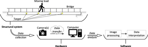
In a short-term bridge monitoring, dynamic and static responses are frequently measured for the assessment of bridge performance (Adhikari, Moselhi, and Bagchi Citation2014). The motion of targets such as bolts or natural and artificial patterns on the structure can be translated to structural response when their locations over time are measured (Brownjohn, Xu, and Hester Citation2017). Each image frame consists of several million pixels. For example, an off-the-shelf action camera can record a 4k video, which is composed of 24 or more 3840 × 2160 pixel image frames per second, each image having 8.29 million pixels, turning the camera into a multipoint/distributed sensor (Busca et al. Citation2014). A target can consist of several hundreds of pixels making a distinctive and recognisable pattern. A target is either identified by a user in the reference frame or detected when searching for a pre-defined template using a range of available image processing libraries and algorithms (Dong and Catbas Citation2020). The multitude of available pixels in a frame allows selecting a desired amount of targets, which might be objects that are not related to the structure and are not subjected to movements when the structure is loaded. Such objects can be used to remove measurement redundancy and camera movements, a task in the data interpretation stage.
3.3. Hardware for vision-based measurement
The basic hardware needed for the vision-based measurement is a camera and a computer, which, in the era of technology, are available in any engineering office. As for any other technology, the range of cameras, camera lenses, camera support systems (e.g. tripods) and computers are as wide as their prices. Action cameras and smartphones are cost-effective and widely available, thus making them an attractive option for vision-based monitoring. Both action cameras and smartphones can be enhanced with telescopic lenses offering a close view of the region of interest (ROI) with a target(s) on the bridge (Kromanis and Kripakaran Citation2021; Lydon et al. Citation2019). Research studies have (i) evaluated the performance of action cameras and smartphones in the laboratory environment and in situ, and (ii) compared response collected with a range of cameras and computed with available image processing algorithms and software (proprietary and open source) (Kromanis et al. Citation2019; Xu, Brownjohn, and Huseynov Citation2019). Most importantly, the studies affirm that accurate structural response can be measured using action cameras (or other available cameras) and open-source algorithms/software.
3.4. Data processing
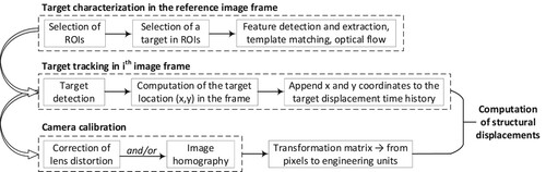
Real-time and post-processing image analysis options can be considered. Real-time target tracking options are usually available when a camera, usually via USB or ethernet cable, is directly connected to the computer (Feng and Feng Citation2018). Also smartphone applications that provide real-time measurement acquisition (such as D-Viewer (Zhao et al. Citation2016), which tracks the location of a blob) are available. However, the common practice, when deploying cost-efficient cameras, is to post-process the collected data (e.g. videos or images). Steps for both real-time and post-processing options are similar. The most commonly employed steps and processes for measuring bridge deformations, according to Kromanis et al. (Citation2019); Lydon et al. (Citation2019); Xu, Brownjohn, and Huseynov (Citation2019), are summarised in and described subsequently.
Target characterisation is the first step of the image processing, in which targets, which are sought in consecutive image frames, with their associated features are defined. In bridge monitoring, target movements are small; therefore, first, ROIs, in which targets lie, are selected. A single target is chosen in each ROI. When a new image is analysed, targets are sought only in the specified ROIs rather than in the entire image, therefore avoiding errors that can result when multiple similar targets are located in a single ROI or image frame. A target is characterised using a suitable feature detection technique. Frequently employed techniques in bridge monitoring are template matching (Stephen et al. Citation1993) and key point and feature extraction/matching (Dong et al. Citation2020; Khuc and Catbas Citation2017; Lydon et al. Citation2019). Characteristics of each target are stored and made available for the next step.
Target tracking step requires no user input. Here, new image frames are loaded in the order following their collection. The defined ROIs are extracted, and the defined targets are sought in the ROIs. When the target location is matched in the ROI, its x and y coordinates in the image are appended to measurement histories. In this step, target coordinates are in the image plane (i.e. in pixels). They are converted to structural plane in the final image processing step.
Camera calibration is the last step before pixel values can be converted to engineering values (e.g. millimetres). In general, it consists of the derivation of camera-intrinsic (related to the camera and lens) and -extrinsic (relationship between the camera and structure) parameters (Ikeuchi Citation2014). Camera-intrinsic parameters can be used to correct the image distortion caused by the camera lens. Smartphones and action cameras, as a default, have a wide-angle lens, which usually results in a slight ‘fisheye’ effect, creating a panoramic or spherical visualisation of the surrounding. In the bridge monitoring, when small movements need to be accurately tracked, cameras are complimented with zoom lenses, which are narrow angle, therefore requiring very little if any corrections. It is also important to note that targets move very few pixels, thus making very little or negligible difference between target movements before and after the application of the lens correction (Xu, Brownjohn, and Huseynov Citation2019). Therefore, the derivation of intrinsic parameters is optional. The compulsory step is the generation of the relationship between the 2D image plane (pixels) and 2D plane of the structure’s surface (e.g. millimetres). This can be achieved by either defining the scale factor or using image homography method (Kromanis et al. Citation2019; Xu, Brownjohn, and Kong Citation2018). Defining the scale factor is the easiest option. It involves (i) measuring a known distance in the x and y axes in the image plane (in pixels) and (ii) calculating the scale factor (i.e. quotient of a distance in the image and on the structure) (Lydon et al. Citation2019). In the planar homography method, structure’s coordinates of at least four key points are matched with the points in the image plane to generate a transformation function (Xu, Brownjohn, and Kong Citation2018). This method requires either structural plans or measuring distance between multiple points of interest on the structure. The transformation function(s) (for intrinsic and/or extrinsic parameters) are passed to the next step.
The final step is the application of transformation function to convert pixel motions of targets to their corresponding structural displacements. Target displacements can be either directly used as values of vertical and horizontal structural displacements or they can be used to compute displacement derivatives such as strains, inclination angles and curvatures. The response is then used to assess the performance of the structure, a task in the data interpretation stage.
Figure 2. Image processing steps for the computation of structural response.
3.5. Data interpretation
A meaningful data interpretation is still the key to a reliable performance assessment of bridges. The first step is that the measurement preparation involves removal of measurement noise and drifts. The cause of measurement noise, for example, can be a missed feature in the target in a frame and/or camera movements resulting from ground vibrations and wind. High-frequency noise can be removed with a high-pass filter. Fast Fourier transforms can be applied to compute the measurement frequency spectrum, from which the specification for a high-pass filter and moving average window can be defined, together with the frequency range of bridge vibrations. Measurement drifts, which could result from drifts of internal camera sensor or slow settlements of the tripod, are usually lasting long or are continuous, depending on the duration of the monitoring event. They can be removed, for example, using moving average filters of long window sizes.
4. Case study
A 27.6-m long and 2-m wide simply supported steel girder pedestrian bridge with timber guardrails and deck serves as a case study to illustrate vision-based bridge monitoring. The bridge is located on the University of Twente (UT) campus, the Netherlands. shows the UT Campus Bridge and locations of the cameras, a Samsung S8 smartphone and a modified GoPro action camera with a zoom lens, further referred to as Smartphone and GoPro, respectively. The bridge is loaded by a single person crossing it and jumping at its mid-span. lists experimental cases on the bridge during the measurement collection event. Through analysing the process of how ‘input’ in the form of images from cameras is transformed into visible ‘output’ representing bridge displacements, the case study supports the philosophical reflection on this transformation process.
Figure 3. The UT Campus Bridge (as captured with Smartphone) and vision-based monitoring system.
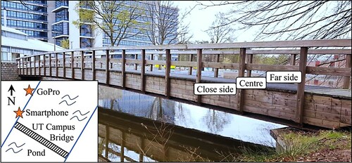
Table 1. Description of experimental cases.
In the case study, measurement histories of structural response such as mid-span deflections (i.e. vertical displacement of a target) consist of static (e.g. pedestrian crossings) and dynamic (resonant vibration of the bridge emphasised by footsteps) components. The bridge baseline performance, which defines bridge conditions, is derived from a dataset, i.e. response measurements, load and its path, and temperature, which ideally is captured over a duration of an entire year. The data must contain controlled crossings, in which the weight of the pedestrian and the crossing path are known, at different seasons, when the ambient temperature varies. Deviations in bridge baseline and current (i.e. at ith measurement collection event) conditions are indicators of a change in the bridge performance or damage, which may require interventions from the bridge management team. When the bridge performance is analysed, probabilistic techniques quantifying bridge’s natural wear and tear and fatigue have to be considered. The indices, coefficients that are used to approximate these phenomena, are unique for the type of the bridge and are not discussed in this manuscript.
Raw vertical displacement histories of the target (in millimetres) are plotted in . Measurement drifts are discernible in both response histories. Displacements from Smartphone data are noisier than from GoPro making the first four cases undistinguishable. GoPro-measured displacements have recognisable trends for all cases. Some obvious outliers are visible in displacements, for example, two downward spikes at around 100th and 210th seconds.
Figure 4. Vertical displacements of the target from the image processing: Smartphone (left) and GoPro (right). Numbers in the boxes correspond to the cases listed in .
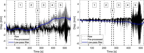
Raw measurement histories are pre-processed using both high-pass and moving average filters. First, the high-pass filter of 10 Hz is applied to remove high-frequency noise and outliers. Then a 1-min moving average filter is used to remove camera movements/drifts without removing static response components. The selection of measurement pre-processing filters can be done (i) either by using an engineering judgement and having prior knowledge of activities and their durations on the structure, (ii) or by transferring signals from time to frequency domain, for example, applying fast Fourier transform and identifying frequencies corresponding to the first dynamic modes and durations of static load applications. The raw and pre-processed measurement histories with the chosen low-pass (or moving average) filter are given in . The application of filters is noticed to remove high-frequency data, outliers and measurement drifts. Smartphone-measured displacements still remain noisy and only Case 5 is distinguishable in the displacement history.
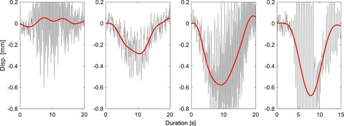
To have a better understanding of the bridge behaviour, the first crossing from each case (i.e. when the person crossed the bridge from NW to SE direction) is depicted in . The walking speed was around 5.5 km/h and jogging speed is 8.5 km/h. Therefore, 20 and 15 s windows for Cases 1–3 and Case 4, respectively, are chosen. In Case 3, the static response is the largest of the cases with a person walking. For Case 4, the bridge has a similar static response pattern as for Case 3; however, the maximum displacement is slightly larger. This could be attributed to the increased dynamic force, location of the person on the bridge, measurement error and/or measurement pre-processing.
Figure 5. Bridge response (grey line) and its static component (red line) for the first crossing of Cases 1–4 (left to right).
5. Technological mediation and vision-based systems
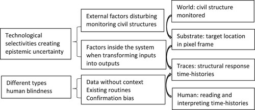
Two postphenomenological concepts are used to discuss how vision-based systems transform users’ perception of a civil structure: built-in selectivities of a technology and different types of human blindness (). This discussion provides insights into the main aspects of the technological mediation approach.
Figure 6. Technological mediation concepts and vision-based systems.
5.1. Technological selectivities
When the relationship of composite intentionality involves a vision-based system for bridge monitoring, it can be modified to human → (vision-based system → bridge) (Verbeek Citation2008). Like the system model of Carmichael (Citation2020), this equation models in an elementary form the connection between what is going into and coming out the system. This connection is based on the technological directedness of a vision-based system and its several built-in selectivities or ‘biases’. These technological ‘biases’ or selectivities determine possible differences between the modelled structural response histories provided by the vision-based system and existing civil structures in reality (Thunnissen Citation2003). These differences attribute to so-called epistemic uncertainties. Epistemic uncertainty derives from the lack of knowledge of a parameter, phenomenon or process (Basu Citation2017). In the case of vision-based systems, it occurs either from transforming inputs into outputs inside these systems or from external factors disturbing monitoring civil structures (Zio and Pedroni Citation2012).
The built-in selectivities related to the camera’s intrinsic and extrinsic parameters may create epistemic uncertainties when inputs are transformed into outputs inside vision-based systems. The first selectivity concerns the selection of a ROI and a specific target within the specified ROI. The ‘sensing apparatus’ of the camera, e.g. in GoPro or Smartphone, is configured to capture a large number of pixels within an image frame. Based on these pixels, targets within certain ROIs are chosen, and their coordinates on x and y axes are computed. To convert pixel values into engineering values (e.g. millimetres), two built-in selectivities are needed. Related to the transformation of input into output, one built-in selectivity causing epistemic uncertainty is the camera’s intrinsic parameters, i.e. correction of the image distortion such as the ‘fisheye’ effect when using wide-angle lenses. Another built-in selectivity causing epistemic uncertainty due to this transformation is the setting of a camera’s extrinsic parameters, such as the scale factor or performing the image homography method, for transforming the coordinates of the target from the 2D image plane (i.e. pixels) to the 2D plane of the structure’s surface (e.g. millimetres).
Epistemic uncertainty may also be created by external factors when using a vision-based system, such as ground vibration and wind. For an accurate measurement of the motion of targets, two other built-in selectivities for data post-processing may be needed. Measurement noise caused by, for example, camera movements (ground vibration, wind) can be removed with the built-in selectivity of a so-called high-pass filter. Measurement drifts, which could result from drifts of internal camera sensor or slight movements of tripod, can be removed by the built-in selectivity of moving average filters of relatively long window sizes or selecting a background object which is not related to the structure.
When vision-based systems are thought of as responsive digital material, the substrate in the case study is the image frames consisting of millions of pixels. These image frames are the interface between the objects in the world, specific targets within the specified ROIs of the bridge monitored and its representation in terms of structural response time-histories. The structural response time-histories are the traces to be interpreted by their users. These traces are the result of a translation of the motion of targets. Producing these traces is based on the previously discussed technological built-in selectivities through data pre- and post-processing of the pixels within the image frames (Ihde Citation2015).
In terms of responsive digital materials, technological mediation through a vision-based system can be represented as users → ([structural response time-histories | image frames] → targets in ROI). Pre-processing of the pixels occurs when image frames are transformed into structural response time-histories. Post-processing of the pixels within the image frames is needed to correct measurement errors of the specific targets of the bridge monitored created by external factors while using a vision-based system, such as ground vibration and wind. Pre- and post-processing of the substrate through these technological selectivities determine possible differences between modelled time-histories and reality.
5.2. Types of human blindness
Human intentionality involves users turning to a vision-based system for bridge monitoring in order to read and interpret the structural response time-histories that it provides (Rosenberger and Verbeek Citation2015). The user is directed towards a certain object in the world. Reading and interpretation of these time-histories by their users involved in civil structure monitoring are first influenced by the technological ‘selectivities’ just discussed.
Structural response time-histories as a result of these selectivities amplify a person’s experience of a certain aspect of the monitored bridges (such as the precise deformation of the bridge at target locations), while simultaneously reducing experiences of other aspects of the bridge (Ihde Citation1990). This amplification and reduction are based on the technological selectivities discussed. Raw measurements are processed using correction of image distortion, image homography, and high-pass and moving average filters. There is always a certain random noise in the measurement system. A feature in the target could be missed and may cause errors in measurement and interpretation. That is why it is important that an engineer relies not just on these pre-processed filtered data in interpreting structural response time-histories for his/her decision-making.
Turk (Citation2001b) discusses in this context the ‘blindness’ that could be experienced if engineers do not recognise their ‘thrownness’ in a specific context – a typical Heideggerian concept. In case engineers start to think reflectively about civil structure conditions in terms of the structural response time-history provided through the vision-based system, they ‘disconnect’ themselves from their ‘thrownness’ in the specific context of a civil structure and its characteristics. Through reduction and amplification by the vision-based system, blindness may be created for other aspects of reality. Engineers limit their view to the aspects of reality, which can be expressed in the model (in the case the structural response time-history). This limitation is a result from technological selectivities as programmed and designed in the vision-based system.
Heidegger’s concept of thrownness can also create another type of human blindness. It is related to practices that engineers are socialised into, prior to any theoretical understanding (Dias Citation2006, p. 524). Established practices and routines create ‘the ability to act pre-reflectively when ‘thrown’ into a situation' (Turk Citation2001a, p. 249). Similar pre-reflective actions and interpretations are the so-called ‘intuition’, ‘insight’ or ‘common sense’, that are sometimes used by engineers to explain their views (Turk Citation1998). These ‘pre-theoretical’ shared agreements and routines in engineering practices may also create a ‘blindness’ for using new measurement processing tools and practices (Turk Citation2001a, p. 249). In the case study, this blindness may result in an automatic selection of tools, e.g. the selection of measurement processing filters, which are already part of the existing monitoring practice.
Another type of ‘blindness’ related to these ‘pre-theoretical’ shared agreements that influence interpretation of structural time-histories is the widely studied confirmation bias (Nickerson Citation1998). This blindness may result in interpreting time-histories in ways that match existing expectations and experiences and possibly disregard information that does not match these. Carmichael (Citation2020) refers to the background of a person in terms of experience, knowledge, education and discipline as the sources of such a bias.
Engineers using SHM systems must ensure that SHM systems represent displacements as faithfully as possible, in order to minimise epistemic uncertainties and recognise that outputs of these systems have also to be judged in the light of the specific pre-theoretical shared agreements and routines. It is important that human interpretation compensates for the epistemic uncertainties of the modelled reality. In that case, models help the routine, day-to-day work a lot and lead to improved decision-making.
6. Conclusions
The study’s aim was to explore what kind of technological mediation a vision-based system provides between their users and civil structure conditions that are unperceivable in a great part by humans. Providing insights into the ways in which vision-based systems receive inputs and transforming them into outputs in a relationship of composite intentionality is the basis for a philosophical reflection on understanding the mediating role this technology plays in monitoring practice.
A vision-based system for civil structure monitoring was conceived as a responsive digital material with a substrate and a trace (Wiltse Citation2014): human → ([trace |substrate] → world). Here, the image frame consisting of millions of pixels is the substrate, and the structural response time-histories are the traces to be interpreted by their users. Producing these traces is based on a number of built-in technological selectivities of the vision-based system pre- and post-processing the substrate. It was discussed that this data processing through these selectivities determines possible differences between the modelled structural response histories and existing civil structures in reality and attribute to epistemic uncertainties.
The properties of civil structures monitored through technological selectivities are made accessible to humans through reduction and amplification of the data collected. Through this reduction and amplification, human blindness may be created for other aspects of reality. Blindness may occur when engineers rely either only or too much on filtered data for their decision-making rather than recognising their ‘thrownness’ in the given context of a project. In that case, engineers limit their view to that, which can be expressed in modelled aspects of civil structures as programmed and designed in the vision-based system. The thrownness into existing engineering practices and routines may, on the other hand, also create a ‘blindness’ for using new measurement processing tools and practices. Related to this, blindness is the confirmation bias: interpretation based on matching existing expectations and experiences.
Reflections on Verbeek’s concept of composite intentionality show that components of a vision-based system involve intentionality from both the developer (technological selectivities designed and programmed into this system by its developers) and the user (human intentionality involves different types of blindness of users when reading and interpreting the output of the system). Providing insights into technological selectivities and different types of human blindness contributes to more realistic expectations about what vision-based systems can do to enhance the quality of decision-making on civil structure performance and maintenance. Understanding this complex interplay eventually may help to develop better systems, and may increase our understanding of how these systems are adopted more successfully.
The major contribution of this study is that two fields of research are connected: the operation of vision-based SHM systems and the technological mediation perspective. Connecting both fields increases the understanding of the mediating role that vision-based SHM systems play in monitoring practice and contributes to a more realistic expectations about what vision-based systems can do to enhance the quality of decision-making on civil structure bridge performance and maintenance.
Disclosure statement
No potential conflict of interest was reported by the author(s).
Data availability statement
Raw data were generated at the University of Twente. Data supporting the findings of this study are available from the corresponding author upon a request.
References
- Aagaard, J. 2017. “Introducing Postphenomenological Research: A Brief and Selective Sketch of Phenomenological Research Methods.” International Journal of Qualitative Studies in Education 30 (6): 519–533. doi:https://doi.org/10.1080/09518398.2016.1263884.
- Adhikari, R., O. Moselhi, and A. Bagchi. 2014. “Image-Based Retrieval of Concrete Crack Properties for Bridge Inspection.” Automation in Construction 39: 180–194. doi:https://doi.org/10.1016/j.autcon.2013.06.011.
- Basu, S. 2017. Plant Hazard Analysis and Safety Instrumentation Systems. London: Elsevier.
- Brownjohn, J. M. 2007. “Structural Health Monitoring of Civil Infrastructure.” Philosophical Transactions of the Royal Society A: Mathematical, Physical and Engineering Sciences 365 (1851): 589–622. doi:https://doi.org/10.1098/rsta.2006.1925.
- Brownjohn, J. M. W., Y. Xu, and D. Hester. 2017. “Vision-Based Bridge Deformation Monitoring.” Frontiers in Built Environment 3: 23. doi:https://doi.org/10.3389/fbuil.2017.00023.
- Busca, G., A. Cigada, P. Mazzoleni, and E. Zappa. 2014. “Vibration Monitoring of Multiple Bridge Points by Means of a Unique Vision-Based Measuring System.” Experimental Mechanic 54 (2): 255–271. doi:https://doi.org/10.1007/s11340-013-9784-8.
- Carmichael, D. G. 2020. “Bias and Decision Making – An Overview Systems Explanation.” Civil Engineering and Environmental Systems 37 (1-2): 48–61. doi:https://doi.org/10.1080/10286608.2020.1744133.
- Choi, H.-S., J.-H. Cheung, S.-H. Kim, and J.-H. Ahn. 2011. “Structural Dynamic Displacement Vision System Using Digital Image Processing.” NDT & E International 44 (7): 597–608. doi:https://doi.org/10.1016/j.ndteint.2011.06.003.
- Dias, W. P. S. 2006. “Heidegger’s Resonance with Engineering: The Primacy of Practice.” Science and Engineering Ethics 12: 523–532. doi:https://doi.org/10.1007/s11948-006-0050-7.
- Dong, C.-Z., and F. N. Catbas. 2020. “A Review of Computer Vision–Based Structural Health Monitoring at Local and Global Levels.” Structural Health Monitoring 1475921720935585. doi:https://doi.org/10.1177/1475921720935585.
- Dong, C.-Z., O. Celik, F. N. Catbas, E. J. O’Brien, and S. Taylor. 2020. “Structural Displacement Monitoring Using Deep Learning-Based Full Field Optical Flow Methods.” Structure and Infrastructure Engineering 16 (1): 51–71. doi:https://doi.org/10.1080/15732479.2019.1650078.
- Dong, Y., R. Song, and H. Liu. 2010. Bridges Structural Health Monitoring and Deterioration Detection Synthesis of Knowledge and Technology (No. AUTC# 309036). Alaska: Dept. of Transportation and Public Facilities.
- Dutton, M., W. A. Take, and N. A. Hoult. 2014. “Curvature Monitoring of Beams Using Digital Image Correlation.” Journal of Bridge Engineering 19 (3): 05013001. doi:https://doi.org/10.1061/(ASCE)BE.1943-5592.0000538.
- Enckell, M., B. Glisic, F. Myrvoll, and B. Bergstrand. 2011. “Evaluation of a Large-Scale Bridge Strain, Temperature and Crack Monitoring with Distributed Fibre Optic Sensors.” Journal of Civil Structural Health Monitoring 1 (1–2): 37–46. doi:https://doi.org/10.1007/s13349-011-0004-x.
- Farrar, C. R., and N. A. Lieven. 2006. “Damage Prognosis: The Future of Structural Health Monitoring.” Philosophical Transactions of the Royal Society A: Mathematical, Physical and Engineering Sciences 365 (1851): 623–632. doi:https://doi.org/10.1098/rsta.2006.1927.
- Feng, D., and M. Q. Feng. 2018. “Computer Vision for SHM of Civil Infrastructure: From Dynamic Response Measurement to Damage Detection – A Review.” Engineering Structures 156: 105–117. doi:https://doi.org/10.1016/j.engstruct.2017.11.018.
- Gastineau, A., T. Johnson, and A. Schultz. 2009. Bridge Health Monitoring and Inspections – A Survey of Methods. Minneapolis: University of Minnesota.
- Ho, D.-D., K.-D. Nguyen, P.-Y. Lee, D.-S. Hong, S.-Y. Lee, J.-T. Kim, S.-W. Shin, C.-B. Yun, and M. Shinozuka. 2012. “Wireless Structural Health Monitoring of Cable-Stayed Bridge Using Imote2-Platformed Smart Sensors.” In Proc. SPIE 8345, Sensors and Smart Structures Technologies for Civil, Mechanical, and Aerospace Systems, 83450 T (26 March 2012).
- Hong, T., and M. Hastak. 2005. “MEMRRES: Model for Evaluating Maintenance, Repair and Rehabilitation Strategies in Concrete Bridge Decks.” Civil Engineering and Environmental Systems 22 (4): 233–248. doi:https://doi.org/10.1080/10286600500392742.
- Husserl, E. 1983. Ideas pertaining to a pure phenomenology and to a philosophical phenomenology. Kluwer Academic Publishers.
- Ihde, D. 1986. Experimental Phenomenology: An Introduction. Albany: SUNY Press.
- Ihde, D. 1990. Technology and the Lifeworld: From Garden to Earth. Bloomington: Indiana University Press.
- Ihde, D. 1998. “Whole Earth Measurements.” Philosophy and Technology 2 (2): 61–72.
- Ihde, D. 2009. Postphenomenology and Technoscience: The Peking University Lectures. Albany: Suny Press.
- Ihde, D. 2015. “Positioning Postphenomenology.” In Postphenomenological Investigations: Essays on Human–Technology Relations, edited by R. Rosenberger and P.-P. Verbeek, vii–xvi. London/New York: Lexington Books.
- Ikeuchi, K. 2014. Computer Vision: A Reference Guide. Cham: Springer.
- Khuc, T., and F. N. Catbas. 2017. “Computer Vision-Based Displacement and Vibration Monitoring Without Using Physical Target on Structures.” Structure and Infrastructure Engineering 13 (4): 505–516. doi:https://doi.org/10.1080/15732479.2016.1164729.
- Khuc, T., and F. N. Catbas. 2018. “Structural Identification Using Computer Vision–Based Bridge Health Monitoring.” Journal of Structural Engineering 144 (2): 04017202. doi:https://doi.org/10.1061/(ASCE)ST.1943-541X.0001925.
- Kromanis, R., and P. Kripakaran. 2021. “A Multiple Camera Position Approach for Accurate Displacement Measurement Using Computer Vision.” Journal of Civil Structural Health Monitoring 11: 661–678. doi:https://doi.org/10.1007/s13349-021-00473-0.
- Kromanis, R., Y. Xu, D. Lydon, J. Martinez del Rincon, and A. Al-Habaibeh. 2019. “Measuring Structural Deformations in the Laboratory Environment Using Smartphones.” Frontiers in Built Environment 5: 44. doi:https://doi.org/10.3389/fbuil.2019.00044.
- Lydon, D., M. Lydon, S. Taylor, J. M. Del Rincon, D. Hester, and J. Brownjohn. 2019. “Development and Field Testing of a Vision-Based Displacement System Using a low Cost Wireless Action Camera.” Mechanical Systems and Signal Processing 121: 343–358. doi:https://doi.org/10.1016/j.ymssp.2018.11.015.
- Nickerson, R. S. 1998. “Confirmation Bias: A Ubiquitous Phenomenon in Many Guises.” Review of General Psychology 2 (2): 175–220. doi:https://doi.org/10.1037/1089-2680.2.2.175.
- Nielsen, L., S. T. Glavind, J. Qin, and M. H. Faber. 2019. “Faith and Fakes – Dealing with Critical Information in Decision Analysis.” Civil Engineering and Environmental Systems 36 (1): 32–54. doi:https://doi.org/10.1080/10286608.2019.1615476.
- Ri, S., H. Tsuda, K. Chang, S. Hsu, F. Lo, and T. Lee. 2020. “Dynamic Deformation Measurement by the Sampling Moiré Method from Video Recording and its Application to Bridge Engineering.” Experimental Techniques 44: 313–327. doi:https://doi.org/10.1007/s40799-019-00358-4.
- Rosenberger, R. 2008. “Perceiving Other Planets: Bodily Experience, Interpretation, and the Mars Orbiter Camera.” Human Studies 31 (1): 63–75. doi:https://doi.org/10.1007/s10746-007-9078-1.
- Rosenberger, R. 2011. “A Case Study in the Applied Philosophy of Imaging: The Synaptic Vesicle Debate.” Science, Technology, & Human Values 36 (1): 6–32. doi:https://doi.org/10.1177/0162243909337117.
- Rosenberger, R., and P.-P. Verbeek. 2015. Postphenomenological Investigations: Essays on Human–Technology Relations. London/New York: Lexington Books.
- Seyedpoor, S. M., S. Shahbandeh, and O. Yazdanpanah. 2015. “An Efficient Method for Structural Damage Detection Using a Differential Evolution Algorithm-Based Optimisation Approach.” Civil Engineering and Environmental Systems 32 (3): 230–250. doi:https://doi.org/10.1080/10286608.2015.1046051.
- Stephen, G. A., J. M. W. Brownjohn, and C. A. Taylor 1993. “Measurements of static and dynamic displacement from visual monitoring of the Humber Bridge.” Engineering Structures 15 (3): 197–208. doi:https://doi.org/10.1016/0141-0296(93)90054-8.
- Thunnissen, D. P. 2003. “Uncertainty Classification for the Design and Development of Complex Systems.” In 3rd Annual Predictive Methods Conference. Newport Beach, CA.
- Turk, Z. 1998. “On Theoretical Backgrounds of CAD.” In Artificial Intelligence in Structural Engineering, edited by I. Smith, 490–496. Berlin/Heidelberg: Springer.
- Turk, Ž. 2001a. “Multimedia: Providing Students with Real World Experiences.” Automation in Construction 10 (2): 247–255. doi:https://doi.org/10.1016/S0926-5805(99)00034-5.
- Turk, Ž. 2001b. “Phenomenologial Foundations of Conceptual Product Modelling in Architecture, Engineering and Construction.” Artificial Intelligence in Engineering 15 (2): 83–92. doi:https://doi.org/10.1016/S0954-1810(01)00008-5.
- Verbeek, P.-P. 2001. “Don Ihde: The Technological Lifeworld.” In American Philosophy of Technology: The Empirical Turn, edited by H. Achterhuis and R. P. Crease, 119–146. Bloomington: Indiana University Press.
- Verbeek, P.-P. 2005. What Things Do: Philosophical Reflections on Technology, Agency, and Design. University Park, PA: Penn State Press.
- Verbeek, P.-P. 2006. “Materializing Morality: Design Ethics and Technological Mediation.” Science, Technology, & Human Values 31 (3): 361–380. doi:https://doi.org/10.1177/0162243905285847.
- Verbeek, P.-P. 2008. “Cyborg Intentionality: Rethinking the Phenomenology of Human–Technology Relations.” Phenomenology and the Cognitive Sciences 7 (3): 387–395. doi:https://doi.org/10.1007/s11097-008-9099-x.
- Voordijk, J. T. 2019. “Technological Mediation in Construction: Postphenomenological Inquiry Into Digital Technologies.” Journal of Construction Engineering and Management 145 (12): 04019084. doi:https://doi.org/10.1061/(ASCE)CO.1943-7862.0001719.
- Wellner, G. 2018. “From Cellphones to Machine Learning. A Shift in the Role of the User in Algorithmic Writing.” In Towards a Philosophy of Digital Media, edited by A. Romele and E. Terrone, 205–224. Cham: Palgrave Macmillan.
- Wiltse, H. 2014. “Unpacking Digital Material Mediation.” Techné: Research in Philosophy and Technology 18 (3): 154–182. doi:https://doi.org/10.5840/techne201411322.
- Xu, Y., J. M. Brownjohn, and F. Huseynov. 2019. “Accurate Deformation Monitoring on Bridge Structures Using a Cost-Effective Sensing System Combined with a Camera and Accelerometers: Case Study.” Journal of Bridge Engineering 24 (1): 05018014. doi:https://doi.org/10.1061/(ASCE)BE.1943-5592.0001330.
- Xu, Y., J. Brownjohn, and D. Kong. 2018. “A Non-Contact Vision-Based System for Multipoint Displacement Monitoring in a Cable-Stayed Footbridge.” Structural Control and Health Monitoring 25 (5): e2155. doi:https://doi.org/10.1002/stc.2155.
- Yoon, H., H. Elanwar, H. Choi, M. Golparvar-Fard, and B. F. Spencer Jr. 2016. “Target-Free Approach for Vision-Based Structural System Identification Using Consumer-Grade Cameras.” Structural Control and Health Monitoring 23 (12): 1405–1416. doi:https://doi.org/10.1002/stc.1850.
- Zhao, X., H. Liu, Y. Yu, Q. Zhu, W. Hu, M. Li, and J. Ou. 2016. “Displacement Monitoring Technique Using a Smartphone Based on the Laser Projection-Sensing Method.” Sensors and Actuators A: Physical 246: 35–47. doi:https://doi.org/10.1016/j.sna.2016.05.012.
- Zio, E., and N. Pedroni. 2012. “Uncertainty Characterization in Risk Analysis for Decision-Making Practice.” Number 2012-07, Cahiers de la Sécurité Industrielle. Foundation for an Industrial Safety Culture: Toulouse.