
 ?Mathematical formulae have been encoded as MathML and are displayed in this HTML version using MathJax in order to improve their display. Uncheck the box to turn MathJax off. This feature requires Javascript. Click on a formula to zoom.
Abstract
Lubrication of a wrist pin journal can become a limiting factor in the performance of internal combustion engines. A wrist pin journal is a hydrodynamic bearing with a radial clearance of only a few micrometers that is filled with a mixture of oil and air. Moreover, the radial clearance changes periodically with the piston motion and according to the working cycle of the internal combustion engine. Hence, a numerical study of the flow and oil transport inside a wrist pin journal requires an unsteady 3D two-phase model. Furthermore, the numerical model must include gravity and centrifugal forces, the unsteady rotation of the piston pin, and the oil feed on both sides of the piston pin boss. Presently, neither the oil feed surrounding the piston pin boss nor the mechanism transporting the oil into the gap between the piston and piston pin are fully understood. This study presents a numerical approach describing the lubrication inside the wrist pin journal. A particular aspect of the modeling is combining a structured mesh of hexahedron cells for the narrow gap and unstructured meshing in the surrounding geometry due to the difference in length scale of several orders of magnitude. The numerical model has been validated on test cases and experimental oil transport data obtained from a piston model experiment. The numerical results include images of complex 3D structures of oil and air fractions inside the oil film and in the regions surrounding the piston boss.
Introduction
Downsizing and downspeeding are current trends in the of state-of-the-art design of highly loaded internal combustion engines. Thus, the reliability of the wrist pin journal becomes one of the paramount challenges of the design process of both spark-ignited and compression-ignited engine concepts, because high combustion pressures und temperatures increase the stress on the wrist pin journal, which may result in seizure and friction wear of the bearing. Previously, experimental and numerical projects were launched in order to investigate the effect of friction and wear on the piston pin assembly. One of the first experiments was carried out by Furey (Citation1) to determine lubrication conditions and the film thickness at the wrist pin–piston cylinder contacts by means of seeding mineral oil with a radioactive additive. The experimental results of Zhang, et al. (Citation2) showed that scuffing damage is dependent on the friction coefficient, surface roughness, oil film thickness, and radial clearance of the wrist pin journal. Numerical works on piston assembly were discussed in Wang, et al. (Citation3), Li, et al. (Citation4), and Ba, et al. (Citation5). Wang, et al. (Citation3) investigated the thermal and tribological properties of the piston assembly system, focusing on degreasing in relation to the temperature level at the piston walls. Li, et al. (Citation4) and Ba, et al. (Citation5) carried out simulations of the lubrication flow based on the 2D Reynolds differential equation. Li, et al. (Citation4) studied the influence of piston skirt friction on the piston pin position. Multibody dynamics combined with a 2D lubrication model was used by Ba, et al. (Citation5) to determine the friction in relation to surface deformation of the wrist pin journal and the connecting rod small end bearing. Experimental work by Etsion, et al. (Citation6) studied the effects of various piston coatings and the oil supply rate. The setup was equipped with an oil supply that yielded a volume flow rate in drops per second and results showed an increase in friction when the flow rate was decreased below 1/200 drops per second. Morgenstern, et al. (Citation7) confirmed the positive effect of diamond-like carbon coating. In addition to coatings and oil supply, current research targets design features to improve the durability of the wrist pin journal. Iwasaki, et al. (Citation8) investigated the effects of relief grooves and pin wall thickness. Their results showed improved lubrication at lower engine speeds yet a loss in performance at higher speeds. A study by Cao and Doll (Citation9) dealt with deformation of the wrist pin. They suggested pin contouring according to the bending profile, which expands the contact area under high loads while widening the opening between the pin and liner, which supports the entry of oil into the lubricating film. Roughness and contact temperature were included in the studies by Fridman, et al. (Citation10) and Ligier and Ragot (Citation11), who surmised that the wrist pin journal is mainly operated fully lubricated. A comprehensive overview of methods pertaining to the computation of the lubrication in hydrodynamic bearings was presented by Bonneau, et al. (Citation12). The methods are based on a 2D Reynolds equation for the flow, a 3D energy equation of the temperature distribution inside the lubricating film, and a 3D Fourier analysis of the temperature in the solids in contact with the fluid. The method is well established for the computation of bearings where the oil is introduced through orifices or grooves at a defined pressure and exits at the journal’s extremities as a result of the pressure gradient inside the lubricating film and shear due to shaft rotation, respectively.
Knoll, et al. (Citation13) participated in a research project that resulted in an expansion of an existing tool to compute elastohydrodynamic (EHD) effects that incorporated the particular conditions of the wrist pin journal. The study reflected on the simultaneous dynamics of the piston vs. piston pin and piston pin vs. connecting rod, including their interactions. Calculations were validated by experimental data obtained by in situ measurements at a fired compression-ignited engine. For several operating points of the test engine the simulation of the piston pin load delivered plausible data in accordance with the piston movement; that is, rotation and displacement. There remained, however, other operating conditions for which an acceptable agreement could only be achieved if a time-dependent oil flow rate through the journal was estimated. Blumenthal (Citation14) confirmed these findings and related them to the complex interaction between pin contouring, oil filling ratio, and friction coefficient. In summary, these findings led to the main goal of this work to make EHD computations of wrist pin journals more reliable by replacing the estimation of the oil supply of the oil collar and the resulting oil flow rate with better data. Knoll, et al. (Citation15) surmised that the boundary conditions of the wrist pin journal pertaining to its lubrication are fundamentally different from those of an ordinary plain bearing where the lubricant enters via feedholes or grooves.
Moreover, it is common practice that empirical methods combined with ad hoc solutions characterize the dimensioning of wrist pin journals. In certain cases EHD computations and experimental findings can be contradictory. This unsatisfactory situation led the members of the Research Association for Combustion Engines eV to founding a project user committee dedicated to researching the EHD of a wrist pin journal and to improving knowledge of the fluid dynamics of the lubricant flow inside the wrist pin journal. The ultimate goal of the project is to expand existing simulation methods by including the lubricant flux inside wrist pin journals based on an improved understanding of the oil supply provided by the oil collar of the journal. The means to shed more light on the behavior of these bearings are both experimental and numerical. The work presented here focuses on the numerical approach. However, the prediction of friction and journal load is not included in the 3D simulation, because it is much more efficient to use 2D EHD tools when the particular boundary conditions are properly defined.
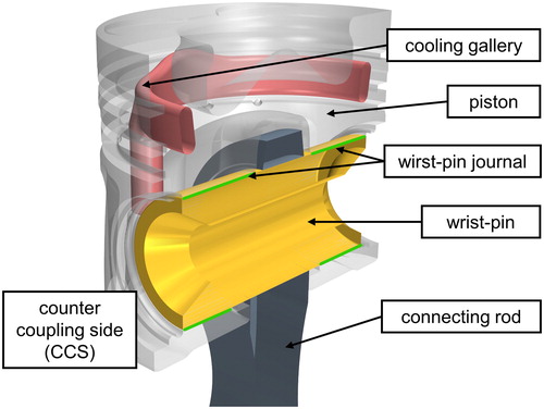
illustrates the main components surrounding the wrist pin journal. The wrist pin connects the piston and connecting rod. At both ends the pin is positioned by means of a circlip. The pin floats between the circlips and there are journals between the piston and wrist pin on both ends. Earlier works (Knoll, et al. (Citation13)) indicate that the pin rotates in a transient manner and shows vertical and lateral displacement, which in turn results in strong changes in the radial clearance. Moreover, these results have shown that knowledge pertaining to lubricant flow is rather sketchy and show the need for an extensive 3D computational fluid dynamics (CFD) simulations combined with refined experimental measures to shed more light on the oil flux through the bearing and its source, the oil collar of the journal, and to identify the key parameters defining the oil flow in magnitude and direction.
Figure 1. Assembly of the wrist pin and piston including the wrist pin journal.
It must be noted at this point that the list of crucial factors that need to be considered in the design of wrist pin journals is rather long; therefore, the project user committee determined the scope of the work presented here based on the results of earlier research work (Knoll, et al. (Citation13)). A major concession with respect to the limitation of computing time was the exclusion of surface roughness from the 3D model. This decision was based on the fact that the components considered in this work show a relative clearance = 108, according to the definition by Bonneau, et al. (Citation16), who specified a purely hydrodynamic regime for
> 3. Hence, it was surmised that time-dependent radial clearance, transient pin rotation, and unsteady oil distribution inside the piston bottom cavity with respect to the piston motion are the important factors. It is well known and common design practice to apply a diamond-like coating to improve the reliability of wrist pins. However, the selection of the experimental methods, which is the subject of a separate paper, prohibits the use of any insulating coatings. Therefore, the characteristic fluid properties such as surface boundary angle and wetting behavior are based on steel, which is a common material used for wrist pins.
A cross section of the journal is shown in , illustrating that oil is available on either side of the journal, in the space between the piston and cylinder wall surrounding the piston pin boss and on the inside of the piston bottom cavity. also indicates the symbols used for the main dimensions. provides a list of the actual values that were significant for the engine under investigation.
Figure 2. Schematic and main dimensions of the wrist pin journal.
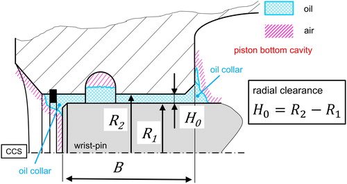
Table 1. General dimensions at operating temperature of the wrist pin journal including relative clearance in relation to roughness according to Bonneau, et al. (Citation16).
Numerical model and mesh generation
Simulation of the complex 3D two-phase flow was performed using the software STARCCM+®, which is based on the finite volume method and utilizes a mass balance equation (Eq. [Citation1]) and the 3D incompressible Navier-Stokes equations (Eq. [Citation2]; Ferziger and Perić (Citation17)), which are expanded by the surface tension term. All equations require transient time-dependent solvers.
[1]
[1]
[2]
[2]
The two-phase flow requires an additional transport equation (Eq. [Citation3]; Ferziger and Perić (Citation17)) for the liquid volume fraction which is normalized by the total volume of the liquid and gas phases (Eq. [Citation4]):
[3]
[3]
[4]
[4]
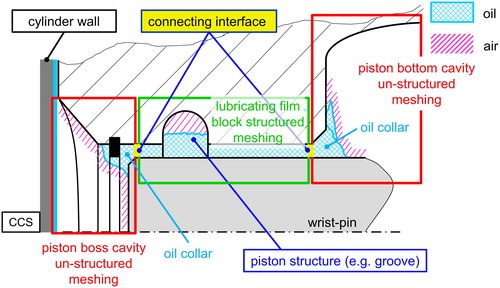
A schematic of the computational domain of the numerical simulation is shown in . The domain is divided into two regions, the piston bottom cavity with an unstructured mesh and the lubricating film of the journal itself with a block-structured mesh. The complex geometry of the piston bottom cavity is meshed by means of the STARCCM + Tool with unstructured polyether cells including wall-adapted boundary layer cells. The grid for the lubricating film between the wrist pin and piston structure is created with the blockMesh tool included in the OpenFOAM library (OpenCFD (Citation18)). The grid is generated as a block-structured mesh with wall-adapted cells to increase numerical accuracy and to ensure that the computing time is acceptable. The authors have successfully applied numerical models of similar complexity in earlier works. The computation (Reinke, et al. (Citation19)) of the transient two-phase Taylor-Couette flow demanded a transient 3D numerical model to compute the double transition from laminar Couette to 3D Taylor vortex flow in combination with the onset of cavitation inside a small gap annulus. Moreover, Reinke and Schmidt (Citation20) have demonstrated that cavitation in hydrodynamic journal bearings has a 3D nature.
Figure 3. Division of the computational domains and meshing approach.
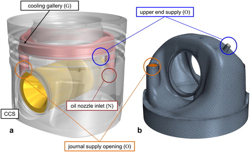
illustrates the solid volume of piston and wrist pin based on computer-aided design data including the openings, which define the oil flow through the system. The oil enters the piston gallery through the oil nozzle inlet (N) and leaves the gallery through two openings (O) into the piston bottom cavity. The fluid volume is extracted from the solid volume resulting in the meshed volume of the piston bottom cavity. The workflow of generating an unstructured mesh based on computer-aided design data is reliable and thus provides the means to map any complex geometry into an efficient mesh structure.
Figure 4. (a) Solid volume and (b) extracted and meshed fluid volume of the piston bottom cavity.
A specifically tailored interface connects the meshing of the lubricating film, which has a block structure, with the piston bottom cavity and its unstructured mesh. All relevant flow variables are transferred between the computing domains across the connection interface. It is of great importance for a conformal matching that the computational domains are facing each other with cross sections equal in size and spatial orientation. Furthermore, the neighboring cells of each domain should be similar in size in order to minimize interpolation errors caused by the transfer of data. The particular features of the domains are illustrated in and . The cell aspect ratio is 7.5, which is well below the maximum value of 10 proposed by Kistner (Citation21).
Figure 5. Block-structured mesh of the wrist pin journal domain.
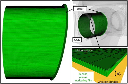
Figure 6. Connecting interface and coupled wrist pin solution domain.
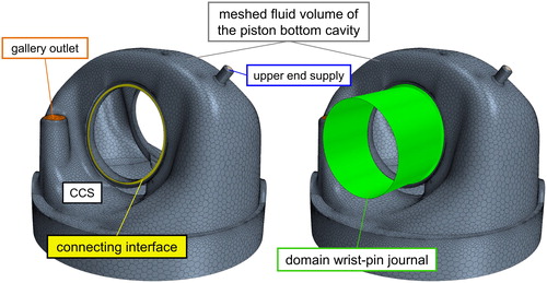
Another feature of the journal domain is the collar, which is tilted against the axis of the wrist pin. The collar (see ) provides the necessary cross section facing the domain of the piston bottom cavity and fills the transition space between the domains. shows the position and orientation of the connecting interface at the piston bottom domain and the assembly of both domains resulting in the total fluid volume, which is meshed for the flow computations.
Finally, the flow domain must contain the cross sections for the oil inlet and outlet, which are indicated in . In this work, the model is derived from an actual test bed engine, where oil is sprayed into the inlet (N) of the oil gallery (G) of each piston by means of an oil nozzle that is fixed to the crankcase. The oil flows through the gallery to maintain the piston cooling and exits into the piston bottom cavity through three outlet openings (O). Because the test engine has no oil supply through the connecting rod aiming to lubricate the upper end bearing, the cooling oil leaving the oil gallery feeds both the upper end bearing and the oil collar of the journal inside the piston bottom cavity.
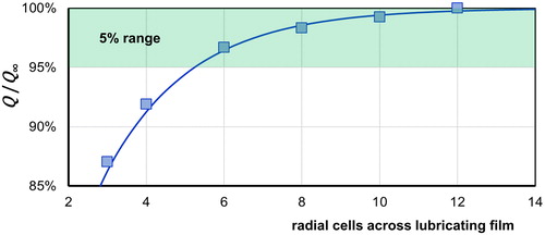
It is known from previous work (Reinke, et al. (Citation19); Reinke and Schmidt (Citation20)) that a minimum number of cells must be applied to the lubricating film in the radial direction. By means of a sensitivity test it was determined that six cells applied to mesh a wrist pin journal achieves the acceptable radial resolution for the expected Reynolds number range. displays the normalized volume flow rate vs. the number radial cells. The trend clearly indicates that a mesh with six radial cells achieves sufficient accuracy and a further increase in the number of cells improves the results only marginally.
Figure 7. Results of sensitivity test for necessary number of radial cells in the structured mesh for the wrist pin domain.
Results and discussion
Any measurement of the oil flow in the journal or its vicinity is a challenge by itself. It must be noted that the numerical study presented in this article is part of a joint project that includes experiments on a piston test rig and inside a six-cylinder V-type combustion engine running on a test bench. Details of the entire scope of the experimental techniques applied are the subject of a future paper. However, researching the oil transport into and through the journal is a crucial subject of the joint project; therefore, a brief description of the method to provide experimental data of the oil flux is given here. At this stage of the joint project experiments were carried out at a piston test bench and the following process steps for the oil flux measurements were observed. The piston and wrist pin assembly was attached to a stationary connecting rod that was rigidly mounted to the test rig. During operation the piston was loaded by means of a hydraulic shaker simulating the dynamic force typical of internal combustion engines. The test rig’s main oil supply provided the general lubrication while the test rig was running.
At time intervals of 2.5 s, oil indicated by a fluorescent agent was injected adjacent to the journal (see ) by means of a 0.32-mm capillary. Hence, the injected oil carried a time-coded mass flow signal, which was detected by measuring the arrival times of the fluorescent agent at selected positions inside the journal gap. At these selected positions, optical fibers (see ) were integrated into the piston to transmit light emitting diode radiation into the lubrication gap exciting the fluorescence, which was captured by the same fibers routing the fluorescent light toward photodetectors. The magnitude of the fluorescent light correlated with the concentration of the injected detection oil inside the surrounding supply oil that passed through the wrist pin journal. A typical set of experimental data is shown in .
Figure 8. Injection capillary (a) in the experiment and (b) in the simulation model.
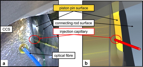
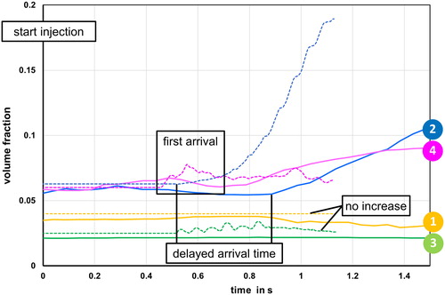
Figure 9. Experimental measurement of oil transport by means of a normalized magnitude of fluorescence of the injected oil.
illustrates how the position of the capillary injection point was modeled in the simulation to ensure that the spatial location met the same position as that in the experiment. In particular, the separation of the oil feed into two individual sources, detection oil and experimental main supply, is a significant feature of the simulation. The amount of injection through the capillary was modeled by means of a mass flow inlet boundary condition, and tracing the fluid from this source resulted in the ability to compute its time-resolved spatial progress. The complex nature of the experimental main oil supply was another challenge. An oil spray nozzle provided the experimental main supply oil flow by spraying the lubricant into the piston cooling channel with lubricating oil. After exiting the cooling channel, the lubricating oil exited into the piston bottom cavity where it wetted the surface of the wrist pin with oil. In order to avoid modeling of the entire cooling channel in the simulation, a mass flow inlet condition was also set at the cooling channel outlet. The Reynolds numbers defined in were used to characterize the flow in experiments and simulations.
Table 2. List of Reynolds numbers.
The Reynolds numbers of the oil supply ReS = 65 and the capillary injection Reinj = 2.5 are defined by the local oil flow rate QS and Qinj together with the outlet diameter D and d, respectively. The flow inside the wrist pin journal is characterized by ReJ = 5.0, which is based on the mean axial velocity u and the radial clearance H0.
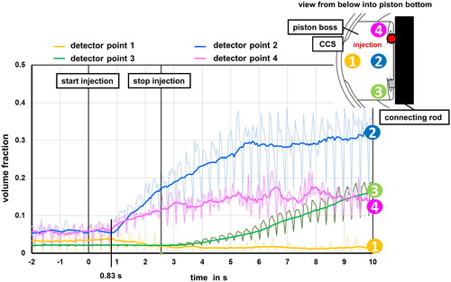
The graphs in present transient detector signals of the optical fiber probes at four positions inside the journal gap. At t = 0.83 s after the start of injection there was a significant increase in the signal at detector point 2 and a moderately rising signal at detector point 4. Detector points 2 and 4 showed a synchronous reaction during the injection, whereas at detector points 1 and 3 no signal increase was recorded.
illustrate the spatial distribution of the injected fluorescent oil at 0.2, 0.49, and 0.75 s, respectively. The simulation is qualitatively equal to the experimental findings regarding the temporal and spatial progression of the transport process of oil into the wrist pin journal. A detailed comparison of numerical and experimental data is shown in . As observed in the experiment, the simulation showed that no oil was transported to detector points 1 and 3. On the other hand, computed data indicate (see and ) that point 4 adjacent to the injection location was the first point where fluorescent oil was found, which was injected through the capillary. Moreover, in the simulation, fluorescent oil arrived at detector point 2 at a time of 0.6 s after injection, slightly earlier than in the experiment, which gives an arrival time of 0.83 s. Conclusively, looking at all four detector points in combination, numerical and experimental results are in good agreement. Main observations such as spatial distribution, arrival times, and gradient coincide with the expected accuracy.
Figure 10. Numerical simulation of the transient distribution of detection oil flow at 0.20 s after injection (iso-surface of 5% fluorescent oil).
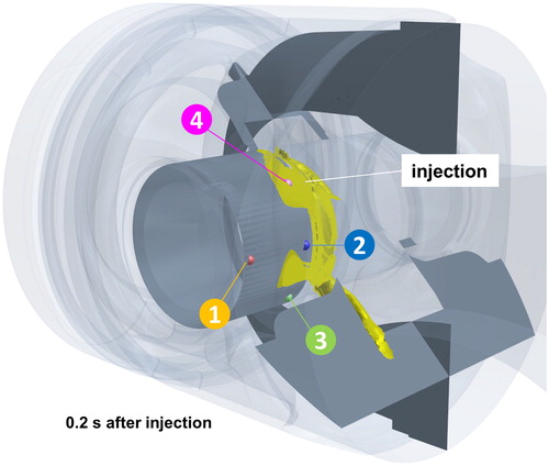
Figure 11. Numerical simulation of the transient distribution of detection oil flow at 0.49 s after injection (iso-surface of 5% fluorescent oil).
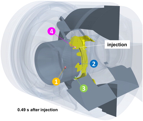
Figure 12. Numerical simulation of the transient distribution of detection oil flow at 0.75 s after injection (iso-surface of 5% fluorescent oil).
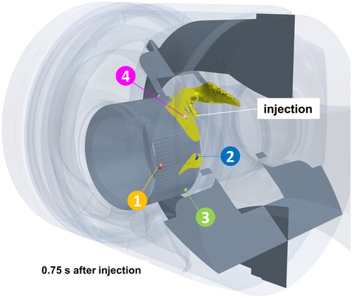
Figure 13. Comparison of numerical results (dotted lines) and experimental data (solid lines) of the oil transport inside a wrist pin journal.
In summary, the 3D computed results of the oil flow agree well with experimental data demonstrating the validity of the transient two-phase numerical model. Next steps include the computation of the transient oil distribution at the oil collar to provide boundary data for the EHD model of the wrist pin journal at an enhanced spatial and time resolution.
indicates that the supply oil was not evenly distributed inside the oil collar. It can be surmised that this is related to the piston design, which features two openings where the oil exits into the piston bottom cavity: the gallery exit, which is on the counter coupling side of the piston, and the boring, which feeds oil into the upper end bearing. Consequently, the magnitude of the oil distribution, which can be observed in , was less than 0.20, because the only source of lubricant was the splash resulting from the upper end oil supply. The splashing motion of the exiting oil resulted in a time-dependent filling of the oil collar and an uneven circumferential distribution around the piston pin. Both characteristics of the oil distribution inside the oil collar make the assumption of a boundary condition with a constant oil offer at the extremity of the wrist pin journal questionable. The study presented here is based on results in relation to a piston testing rig and must be expanded to a full engine including variations in operating parameters.
Figure 14. CFD simulation of the distribution of supply oil inside the oil collar at three consecutive time steps as used in .
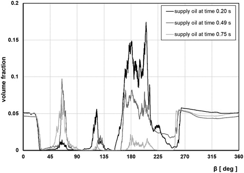
Figure 15. CFD simulation of the distribution of detector oil inside the oil collar at three consecutive time steps in accordance with the spatial distribution given in .
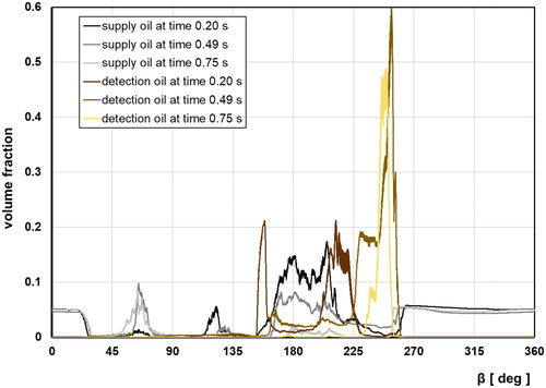
To study the progress of lubricant inside the journal, fluorescent oil was injected by means of a capillary (see ) in the vicinity of a perimeter angle of β = 225° in relation to the inboard oil collar of the wrist pin journal at the counter coupling side. Accordingly, shows the magnitude of fluorescent oil concentrated between β = 160° and β = 240° along the perimeter of the oil collar. Thus, detector points 2 and 4 received fluorescent oil and detector point 3 is located in a nonindicated sector, which matches the results displayed in .
Conclusion
This work presents computations of the lubricant flow inside a wrist pin journal, which were carried out by means of a transient 3D two-phase model. This newly developed model includes wrist pin rotation and displacement based on data samples obtained by test rig experiments with piston–connecting rod assemblies and bench testing with a fired test engine. The numerical results reflect that the oil flow into the bearing depends on the oil supply from the extremities of the journal on both sides of the piston pin boss. Computed data were evaluated with oil flux measurements on a piston test rig and proved that the newly developed model is a useful simulation tool that allows parameter variations to study the main effects that characterize lubrication in a wrist pin journal. In particular, knowledge of the oil distribution of the oil collar is essential for accuracy of the EHD computations, which in turn are needed to improve the piston and wrist pin design. Hence, these efforts will ultimately reduce the risk that lubrication of a wrist pin bearing becomes a limiting factor in the performance of internal combustion engines.
| Nomenclature | ||
| = | Journal width | |
| = | Diameter of the oil supply | |
| = | Diameter of the injection capillary | |
| = | Acceleration vector of gravity | |
| = | Radial clearance | |
| = | Relative clearance | |
| = | Face normal vector | |
| = | Pressure | |
| = | Volumetric flow rate | |
| = | Volumetric injection flow rate | |
| = | Volumetric supply flow rate | |
| R | = | Curvature radius of the free surface |
| = | Wrist pin radius | |
| Ra1 | = | Wrist pin surface roughness |
| Ra2 | = | Journal surface roughness |
| = | Journal bore radius | |
| = | Reynolds number fluorescence oil injection | |
| = | Reynolds number journal | |
| = | Reynolds number oil supply | |
| = | Time | |
| = | Flow velocity | |
| = | Velocity vector | |
| = | Interface compression velocity | |
| = | Volume of the gas phase | |
| = | Volume of the liquid phase | |
| = | Volume fraction | |
| = | Perimeter angle | |
| µ | = | Dynamic viscosity of the liquid |
| ν | = | Kinematic viscosity of the liquid |
| ρ | = | Density of the liquid |
| σ | = | Surface tension |
| = | Nabla operator | |
Acknowledgements
The authors thank the project user committee and Chairman Dr. R.-G. Fiedler for their support and guidance.
Additional information
Funding
References
- Furey, M. J. (1959), “Film Formation by an Antiwear Additive in an Automotive Engine,” ASLE Transactions, 2(1), pp 91–100.
- Zhang, C., Cheng, H. S., and Wang, Q. J. (2004), “Scuffing Behavior of Piston-Pin/Bore Bearing in Mixed Lubrication—Part II: Scuffing Mechanism and Failure Criterion,” Tribology Transactions, 47(1), pp 149–156. doi:10.1080/05698190490279100
- Wang, Q., Cao, Y., and Chen, G. (1996), “Piston Assembly Design for Improved Thermal–Tribological Performance,” Tribology Transactions, 39(2), pp 483–489. doi:10.1080/10402009608983556
- Li, D. F., Rohde, S. M., and Ezzat, H. A. (1983), “An Automotive Piston Lubrication Model,” ASLE Transactions, 26(2), pp 151–160. doi:10.1080/05698198308981489
- Ba, L., He, Z., Liu, Y., and Zhang, G. (2015), “Analysis of Piston-Pin Lubrication Considering the Effects of Structure Deformation and Cavitation,” Journal of Zhejiang University-Science A, 16(6), pp 443–463. doi:10.1631/jzus.A1400105
- Etsion, I., Halperin, G., and Becker, E. (2006), “The Effect of Various Surface Treatments on Piston Pin Scuffing Resistance,” Wear, 261, pp 785–791. doi:10.1016/j.wear.2006.01.032
- Morgenstern, R., Kießling, W., and Reichstein, S. (2008), “Reduced Friction Losses and Wear by DLC Coating of Piston Pins,” Proceedings ASME Internal Combustion Engine Division Spring Technical Conference, Chicago, USA. doi:10.1115/ICES2008-1650
- Iwasaki, H., Higasa, Y., Takiguchi, M., Sue, S., and Shishido, K. (2007), “Effects of Design for Piston Pin and Bearing on State of Bearing Lubrication,” Proceedings ASME Internal Combustion Engine Division Fall Technical Conference, Charleston, USA. doi:10.1115/ICEF2007-1723
- Cao, D. and Doll, G. L. (2008), “Contact Mechanics of a High Load Capacity Piston Pin,” Proceedings STLE/ASME International Joint Tribology Conference, Miami, USA. doi:10.1115/IJTC2008-71121
- Fridman, V., Piraner, I., and Clark, K. (2006), “Modeling of Mixed Lubrication Conditions in a Heavy Duty Piston Pin Joint,” Proceedings ASME Internal Combustion Engine Division Spring Technical Conference, Aachen, Germany. doi:10.1115/ICES2006-1412
- Ligier, J. and Ragot, P. (2005), “Piston Pin: Wear and Rotating Motion,” SAE Paper No. 2005-01-1651.
- Bonneau, D., Fatu, A., and Souchet, D. (2014), Thermo-Hydrodynamic Lubrication in Hydrodynamic Bearings, Wiley: Hoboken, NJ.
- Knoll, G., Bargende, M., Lang, J., Backhaus, K., and Lazzara, M. (2009), “EHD Simulationsverfahren für die Kolbenbolzenlagerung bei Mischreibungskontakt,” FVV-No. 868 (BMWi/AiF-Nr. 14246 N/2), FVV-paper 874.
- Blumenthal, H. (2006), Reibungs- und Verschleißverhalten des Kolbenbolzenlagers bei Elastohydrodynamischer Schmierung, Dissertation, Clausthal-Zellerfeld.
- Knoll, G., Bargende, M., Lang, J., Phillip, U., and Lazzara, M. (2009), “EHD Kolbenbolzen im Mischreibungskontakt,” MTZ Motortechnische Zeitschrift, 70(4), pp 332–328. doi:10.1007/BF03225486
- Bonneau, D., Fatu, A., and Souchet, D. (2014), Mixed Lubrication in Hydrodynamic Bearings, Wiley: Hoboken, NJ.
- Ferziger, J. H. and Perić, M. (2008), Numerische Strömungsmechanik (Computational Methods for Fluid Dynamics), Springer: Berlin-Heidelberg.
- OpenCFD. (2018), OpenFOAM: The Open Source CFD Toolbox: User Guide, Version 1806. Bracknell Berkshire, UK: OpenCFD Limited.
- Reinke, P., Schmidt, M., and Beckmann, T. (2018), “The Cavitating Taylor-Couette Flow,” Physics of Fluids, 30(10), pp 1–10. doi:10.1063/1.5049743
- Reinke, P. and Schmidt, M. (2014), “Lokale, hochauflösende 3D-CFD-Simulation der Schmierspaltströmung in einem instationär belasteten Radialgleitlager,” Abschlussbericht Vorhaben Nr. 1154, FVV e.V. Heft 1073.
- Kistner, B. (1999), Modellierung und Numerische Simulation der Nachlaufstruktur von Turbomaschinen am Beispiel einer Axialturbinenstufe, Ph.D. Thesis, University Darmstadt.